
A workshop compressor starts with a deep hum, the lights dip for a moment, and then everything settles. A refrigerator may make a brief sound as its compressor starts. In a factory, a large pump can demand enough current at startup that engineers must plan the electrical system around those few seconds.
These events are easy to dismiss as “the motor working harder.” That description is partly true, but it misses the electrical mechanism that makes starting current so much larger than normal running current.
Understanding the difference matters when choosing breakers, contactors, cables, generators, transformers, and motor starters. It also helps diagnose nuisance trips, weak starts, overheating, and voltage dips without treating high current as a mysterious fault.
The central idea is simple: a stationary motor has not yet developed the internal voltage that normally limits its current. Once it gains speed, the electrical conditions change dramatically.
⚙️ A Motor Is an Energy Converter
An electric motor converts electrical power into mechanical rotation. Current in its windings produces magnetic fields, and the interaction of those fields creates torque, the turning force at the shaft.
At normal speed, a motor is not merely a coil connected to a supply. Its rotation changes the voltage and current behavior of the windings, which is why a running motor usually draws far less current than it does at the instant of energization.
🚦 Starting Is a Special Operating Condition
At startup, the rotor is stationary. The motor must create enough torque to accelerate its own rotating parts and the attached load, such as a fan, pump, conveyor, or compressor.
There is no stored rotational speed to help the electrical system yet. For a brief period, the motor operates at its most demanding point: high current, low speed, and a need for accelerating torque.
🔌 The Key Concept: Back EMF
When a motor turns, its moving conductors cut magnetic flux and generate a voltage. This generated voltage is called back electromotive force, or back EMF. It opposes the applied supply voltage in the windings.
Back EMF is not an unwanted defect. It is the normal self-regulating feature that limits current as a motor reaches speed. The faster the motor turns, the greater this opposing generated voltage becomes, within its normal operating range.
🧲 Why a Still Rotor Has No Helpful Back EMF
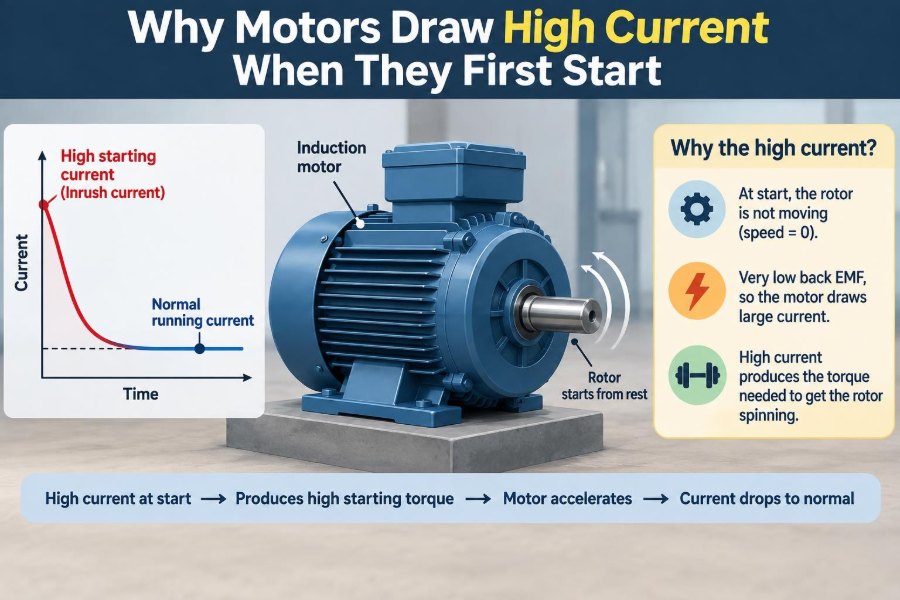
At the exact instant a motor is stopped, rotational back EMF is essentially zero because the rotor is not moving. The supply voltage is therefore opposed mainly by winding resistance and inductive reactance, rather than by a large internally generated voltage.
Motor windings are intentionally made with relatively low resistance. They must carry substantial current efficiently during normal operation. Low resistance is useful for power transfer, but it allows a large current when back EMF is absent.
📐 A Simple Voltage Balance
For a simplified DC motor model, the relationship can be written as V = Eb + I R, where V is supply voltage, Eb is back EMF, I is armature current, and R is winding resistance.
At standstill, Eb is near zero, so current is approximately V/R. As speed rises, back EMF rises and the voltage left to force current through the winding falls. Real AC motors require a more detailed impedance model, but the same physical lesson remains: speed creates a current-limiting electrical effect.
🌊 AC Motors Use Impedance, Not Just Resistance
Induction motors, the common workhorses in pumps, fans, and industrial machinery, run on AC. Their current is limited by impedance: the combined effect of resistance and frequency-dependent inductive reactance.
At standstill, the rotor circuit resembles the secondary of a transformer whose secondary winding is effectively shorted. The stator establishes a changing magnetic field, inducing rotor currents that are initially large. These rotor currents produce starting torque, while the stator draws substantial current from the supply.
🔄 Slip Explains the Induction Motor’s Change in Current
An induction motor’s rotating magnetic field travels at a speed set by supply frequency and pole count. The rotor must rotate slightly slower than that field; this difference is called slip.
At standstill, slip is 100%. Rotor frequency and induced rotor voltage are high, so the motor draws locked-rotor current. As the rotor accelerates, slip falls, rotor electrical behavior changes, and input current declines toward its normal operating value.
🔒 Locked-Rotor Current Is the Relevant Rating
The term locked-rotor current describes the current a motor draws when rated voltage is applied while its rotor cannot turn. It is a test and design condition, not a condition a healthy motor should remain in.
For many induction motors started directly across the line, the initial current can be several times the full-load current. The actual value depends on motor design, voltage, supply impedance, rotor construction, and starting method; it should be taken from the motor’s data rather than guessed.
🏃 Current Falls as the Motor Accelerates
Startup is a transient process. The motor initially draws high current, produces torque, and begins accelerating. As speed builds, its electrical counteraction increases and current normally falls.
A lightly loaded fan may reach speed quickly, so the high-current period is brief. A loaded conveyor, positive-displacement pump, or machine with large rotating inertia may take longer. The duration matters almost as much as the peak current because heating depends on both current and time.
🧱 The Mechanical Load Changes the Story
A motor does not start in isolation. It must accelerate the rotor, couplings, gears, belts, and whatever process equipment is connected. Higher inertia means more energy is required to reach operating speed.
Load torque also matters. A centrifugal fan typically needs relatively little torque at zero speed, while a loaded conveyor may need substantial breakaway torque. A compressor can be difficult to restart if pressure has not equalized.
🌀 Different Loads Have Different Torque Curves
| Load type | Typical startup behavior | Practical implication |
|---|---|---|
| Centrifugal fan or pump | Torque generally rises strongly with speed | Often starts readily; speed control can greatly reduce demand |
| Conveyor | May need high breakaway torque | Starter must provide enough torque without an excessive voltage drop |
| Compressor | Can face pressure-related starting load | Unloading or pressure equalization may be necessary |
| High-inertia machine | Long acceleration time | Thermal duty and start duration need careful review |
These are general patterns, not universal rules. The driven equipment and its operating condition determine the real starting requirement.
⚡ Direct-On-Line Starting Applies Full Voltage
A direct-on-line, or across-the-line, starter connects the motor directly to the full supply voltage. It is simple, reliable, and common for motors where the electrical system can tolerate the inrush and the mechanical load can tolerate the abrupt torque.
Full voltage produces the motor’s available starting torque, but it also produces the highest typical starting current. This is often acceptable for smaller motors or stiff electrical supplies, yet it can be unsuitable where voltage dip affects other equipment.
📉 Voltage Dip Can Affect More Than One Motor
Every supply has some impedance in transformers, cables, switchgear, and generators. When a starting motor draws a large current, voltage drops across that impedance. The voltage at nearby equipment can temporarily sag.
Lights may dim, electronic controls may reset, contactors may chatter, and other motors may lose torque. In a weak installation, the starting motor itself can suffer: lower terminal voltage reduces its starting torque and can make acceleration slower.
🧮 Starting Torque Depends Strongly on Voltage
For an induction motor operating near a given condition, electromagnetic torque is approximately related to the square of applied voltage. A modest voltage reduction can therefore cause a more significant reduction in starting torque.
This creates a design tension. Reducing voltage reduces current, but it also reduces torque. If the motor cannot overcome the load, it remains near standstill, continues drawing high current, and risks overheating. Lower current is not automatically a better start.
🪜 Star-Delta Starting Is a Trade-Off
A star-delta starter begins a suitable three-phase motor in a star connection and later changes it to delta for normal operation. In star, each winding receives lower phase voltage than it would in delta on the same line supply.
That arrangement reduces line current, but it also reduces starting torque substantially. It works only when the motor is designed for the connection and the load can start with the lower torque. It is not a universal cure for inrush.
🧯 Soft Starters Reduce the Initial Electrical Shock
A soft starter uses power semiconductors to gradually increase the voltage applied to an AC motor. It can limit current and reduce mechanical shock in belts, couplings, pipes, and driven equipment.
Because it controls voltage rather than frequency, a soft starter still faces the torque-versus-voltage trade-off. Correct ramp settings depend on the load. An overly gentle ramp can simply lengthen the high-loss acceleration period.
🎛️ Variable-Frequency Drives Start Differently
A variable-frequency drive, or VFD, controls both voltage and frequency supplied to the motor. By starting at low frequency and maintaining an appropriate voltage-to-frequency relationship, it can produce useful torque while keeping current more controlled than a direct-on-line start.
VFDs offer speed control and can be especially valuable for pumps and fans. They also add cost, configuration needs, harmonic considerations, and possible requirements for motor insulation, cable practice, and filtering. They are powerful tools, not automatic upgrades for every application.
🔋 DC Motors Show the Same Principle Clearly
In a DC motor, the connection between speed and current is particularly intuitive. At standstill, there is little back EMF, so armature current can be very high unless a controller limits it.
As the shaft turns, back EMF grows and armature current falls to the level needed for the load. Electronic DC motor drives commonly regulate current precisely for this reason: torque is closely tied to current, and uncontrolled startup current can damage the motor or drive.
🧩 Single-Phase Motors Have Extra Starting Hardware
Single-phase induction motors need a method to create a rotating starting field. Depending on the design, this may involve a start winding, capacitor, centrifugal switch, relay, or electronic control.
Their startup behavior can be more sensitive to a weak capacitor, faulty start switch, low voltage, or excessive load. A motor that hums but does not turn should be disconnected promptly; prolonged locked-rotor current can overheat the windings.
🌡️ Heat Rises Rapidly During a Stall
Winding heating is related to resistive loss, commonly expressed as I²R. When current is several times normal current, heat production in conductors increases very quickly.
A normal start is brief and anticipated by the motor’s thermal design. A stalled rotor, jammed pump, seized bearing, or repeated unsuccessful start is different. The motor can remain at high current without gaining the speed needed to reduce it.
🛡️ Overload Relays and Breakers Do Different Jobs
Motor protection often involves more than one device. Short-circuit protection, such as a fuse or circuit breaker, is intended to interrupt severe fault current and protect conductors from catastrophic faults.
An overload relay or electronic motor protection function is intended to protect the motor from sustained overcurrent and overheating. It must tolerate the normal starting transient while responding to a prolonged overload or stall. Device settings and coordination should follow the motor, starter, conductor, and local installation requirements.
🧷 Why a Normal Breaker May Still Trip
A breaker that trips when a motor starts may be undersized, have an unsuitable trip characteristic, or be responding to a genuine abnormal condition. Replacing it with a larger device without checking conductor capacity and protection coordination is unsafe.
Possible underlying causes include low supply voltage, a jammed load, incorrect motor connection, excessive start frequency, damaged bearings, or a motor that is too small for the load. The trip is useful evidence, not merely an inconvenience.
🔍 Symptoms That Point to a Starting Problem
Observe the pattern before diagnosing. A motor that starts normally but trips after running has a different problem from one that immediately hums and stalls.
- Slow acceleration: low voltage, excessive load torque, or an unsuitable reduced-voltage method.
- Repeated contactor chatter: control voltage dip, loose connections, or inadequate supply capacity.
- Hot smell or rapid thermal trip: stall, phase loss, mechanical binding, or a severe overload.
- High current on one phase: connection, winding, or supply imbalance requiring qualified investigation.
- Hard restart after a stop: residual pressure, thermal state, or a load that has not coasted down.
Measurements should be made with suitable instruments and safe procedures. Motor circuits can contain hazardous voltage, stored mechanical energy, and high fault energy.
📏 Measure Both Current and Voltage
A clamp meter reading alone does not tell the full story. Measure voltage at the motor terminals during the start when practical, because a high current accompanied by a major voltage sag points toward a different problem than high current at healthy terminal voltage.
For three-phase systems, compare all line-to-line voltages and phase currents. Also record acceleration time and load condition. A brief capture from a power-quality analyzer or drive diagnostic tool can reveal events that a slowly updating meter misses.
🧰 Cable and Transformer Sizing Need Starting Duty
Conductors and transformers are not selected from running current alone. Their voltage drop, thermal capability, protective-device coordination, and expected motor starting duty all matter.
Long cable runs add impedance. A motor at the far end of a long feeder may receive noticeably less voltage during start than one beside the distribution board. Engineers may address this with larger conductors, a different starting method, local transformation, or a motor/load combination that accelerates more easily.
🏭 Generator Supplies Need Particular Care
On a utility-connected system, a large network may absorb a motor start with little visible effect. A generator has limited transient capability and its voltage and frequency can dip when a motor is started.
The result depends on generator size, regulator response, engine governor behavior, motor starting method, and other connected loads. Generator-backed motor systems should be evaluated as a system rather than by matching generator rating to motor running power alone.
🔁 Frequent Starts Add Thermal Stress
Even a successful start deposits heat in the motor. If starts occur too frequently, the motor may not have enough time to cool between them, especially in a warm enclosure or at high ambient temperature.
Motor documentation may state allowable starts or starting duty for particular conditions. Where this information is unavailable, repeated trips or rising temperature should not be solved by bypassing protection. The application needs evaluation.
❌ Common Misunderstandings to Avoid
One common mistake is assuming that high starting current means the motor is defective. A short inrush is normal for many motors. The real questions are how large it is, how long it lasts, whether voltage remains adequate, and whether the motor reaches speed.
Another mistake is assuming that a reduced-current starter always protects the motor better. If it provides too little torque, it can extend acceleration and increase thermal stress. The best method matches the electrical supply, motor characteristics, and driven load.
🧠 A Practical Design Checklist
Before specifying or modifying a motor installation, establish the operating facts instead of relying on a single current rating.
- Identify the motor type, rated voltage, full-load current, connection options, and starting data.
- Characterize the load: breakaway torque, inertia, pressure conditions, and required acceleration time.
- Check source capacity and voltage drop through transformer, generator, switchgear, and feeder.
- Choose a starting method that provides adequate torque at acceptable current.
- Coordinate cables, contactors, overload protection, and short-circuit protection.
- Verify performance under realistic worst-case conditions, including low supply voltage where relevant.
✅ The Core Principle to Remember
Motors draw high current at startup because they are initially at zero speed. A DC motor has little or no back EMF, while an induction motor has maximum slip and a rotor condition that demands substantial stator current.
As the motor accelerates, its internal electrical behavior limits current and the demand falls toward the running value. A healthy start is therefore a controlled transition, not an abnormal event. Trouble begins when inadequate voltage, excessive mechanical load, poor starter selection, or a fault prevents that transition from completing.
High starting current is normal when it is brief and the motor accelerates correctly; it becomes a problem when the motor cannot reach speed or the supply and protection system are not designed for the start. ⚡🔧🌀