
A motor nameplate says 30 kW. A panel schedule lists 415 V three-phase. A breaker has an ampere rating, a power-factor correction bank is being considered, and someone asks a deceptively simple question: “So what current will this load actually draw?”
That question appears in workshops, commercial buildings, data rooms, pumping stations, and design calculations. Getting it wrong can mean a conductor that runs too warm, a protection device that trips unnecessarily, or a generator that is specified for the wrong duty.
Three-phase power is often introduced with one compact equation. The equation is useful, but it only becomes reliable when its terms are understood: which voltage is being used, what kind of power is meant, and why power factor changes the current without changing the useful mechanical output in the same way.
The goal is not to memorize a formula in isolation. It is to see the physical relationship behind it, then use it carefully on real electrical loads.
⚙️ Start With the Core Three-Phase Formula
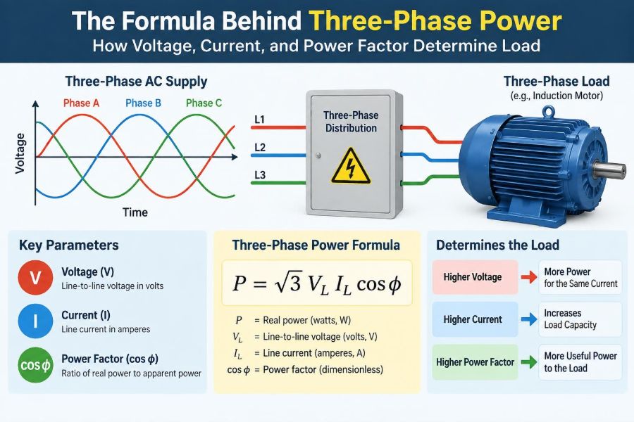
For a balanced three-phase AC load, the real-power relationship is:
P = √3 × VL × IL × PFHere, P is real power in watts, VL is line-to-line voltage in volts, IL is line current in amperes, and PF is power factor. The factor √3, approximately 1.732, comes from the 120-degree spacing of the three phase voltages.
For current, rearrange the equation:
IL = P ÷ (√3 × VL × PF)This is the usual starting point for estimating the running current of a balanced motor or other three-phase load.
🔌 What “Three Phase” Actually Means
A three-phase supply has three sinusoidal voltages of the same frequency and nominal magnitude, separated by 120 electrical degrees. At any instant, their combined ability to transfer energy is much smoother than that of a single-phase supply.
That smooth transfer is especially valuable for motors. A three-phase induction motor develops a naturally rotating magnetic field, giving steady torque and practical self-starting behavior without the auxiliary arrangements commonly needed by single-phase motors.
It also means substantial power can be delivered with a practical conductor arrangement. Three-phase systems are therefore common wherever loads grow beyond ordinary domestic scale.
📏 Separate Line Voltage From Phase Voltage
One of the most frequent calculation errors is inserting the wrong voltage into the wrong formula. Line-to-line voltage is measured between any two live phase conductors. Phase voltage is the voltage across one load phase.
In a wye, or star, connection, the phase voltage is the line-to-neutral voltage. For a balanced system:
VL = √3 × VphaseA 400 V or 415 V three-phase supply normally refers to line-to-line voltage. Its phase-to-neutral voltage is correspondingly lower. The compact power formula above uses line voltage and line current, which makes it convenient for field and design work.
🔺 Why the Square Root of Three Appears
The √3 factor is not a correction selected by convention. It follows from the geometry of three sinusoidal quantities separated by 120 degrees. Their voltage differences and power contributions combine according to vector, or phasor, relationships.
For a balanced load, each phase contributes equal real power. Expressing that total using line voltage rather than phase voltage introduces √3. Using phase quantities instead gives an equally valid form:
P = 3 × Vphase × Iphase × PFBoth expressions produce the same answer when the appropriate voltage and current are paired. Problems arise only when values from different forms are mixed.
💡 Real Power Is the Useful Work Rate
Real power, measured in watts (W) or kilowatts (kW), is the rate at which electrical energy is converted into useful output or losses. In a motor, it supports shaft output plus winding, iron, friction, and ventilation losses.
A resistance heater is a simple example: almost all its electrical real power becomes heat. A motor is more complex because it also needs magnetic fields and has a power factor less than one.
When an energy meter bills a facility for kWh, it is recording accumulated real energy. But real power alone does not fully describe the burden placed on cables, transformers, and switchgear.
📦 Apparent Power Sets Much of the Electrical Capacity
Apparent power is the product of voltage and current before power factor is applied. Its unit is volt-amperes (VA), usually kilovolt-amperes (kVA). For a balanced three-phase system:
S = √3 × VL × ILTransformers, generators, UPS systems, and many distribution components are rated in kVA because heating and current-carrying limits depend strongly on voltage and current, not only on useful watts.
The connection is straightforward: P = S × PF. A 100 kVA load at 0.80 power factor takes 80 kW of real power. The remaining capacity is associated with reactive power.
🧲 Reactive Power Supports Magnetic and Electric Fields
Reactive power, measured in volt-amperes reactive (var or kvar), moves back and forth between the source and reactive components. Inductive equipment such as motors and transformers uses it to establish magnetic fields; capacitors exchange energy through electric fields.
Reactive power is not “wasted power” in the simplistic sense. A motor cannot perform its normal electromagnetic function without magnetizing current. However, reactive current still flows through conductors and creates voltage drop and losses.
For sinusoidal balanced conditions, the familiar power triangle applies:
S² = P² + Q²where Q is reactive power. This right-triangle picture is a useful model, although distorted waveforms require additional care.
📐 Power Factor Is a Ratio, Not a Fixed Property
Power factor is real power divided by apparent power: PF = kW ÷ kVA. Its value ranges from zero to one in ordinary magnitude notation. A higher value means more of the supplied apparent power is doing real work.
At 1.0 power factor, voltage and current are aligned for a sinusoidal load. At 0.80, the same real-power demand requires more current than it would at unity power factor.
Power factor changes with operating conditions. An induction motor often has poorer power factor at light load than near its intended operating region. Treating one nameplate or catalog value as universal can therefore misrepresent an installation.
⏱️ Leading and Lagging Describe Current Timing
With an inductive load, current generally lags voltage. Motors, transformers, and magnetic ballasts are common lagging loads. Capacitive equipment causes current to lead voltage.
The power factor magnitude may be identical in both cases, but the direction of reactive power differs. This matters when applying capacitor correction: capacitors can offset inductive reactive demand, but excessive capacitance can create a leading overall power factor.
Most routine current calculations use the numerical PF magnitude. System studies and correction design must also retain whether the load is leading or lagging.
🧮 A Complete Motor-Load Calculation
Consider a hypothetical balanced load consuming 30 kW at 415 V line-to-line with a running power factor of 0.85. The estimated line current is:
I = 30,000 ÷ (1.732 × 415 × 0.85) ≈ 49 AThe apparent power is 30 kW ÷ 0.85, or about 35.3 kVA. Checking with √3 × 415 V × 49 A produces approximately the same result, allowing for rounding.
This is an estimate of electrical input current under the stated conditions. It is not automatically a final cable or breaker selection, because starting, ambient temperature, installation method, fault protection, and applicable rules also matter.
🏭 Motor Output Power Is Not Always Input Power
Motor ratings are often expressed as mechanical shaft output. If a motor is rated 30 kW output and has 90% efficiency at the operating point, it needs roughly 33.3 kW electrical input before power factor is used to find current.
Pinput = Poutput ÷ efficiencyUsing the earlier 415 V supply and 0.85 power factor, the estimated current becomes about 54.5 A, not 49 A. Confusing output kW with input kW is a common and consequential mistake.
Efficiency and power factor are separate quantities. Efficiency compares electrical input with mechanical output; power factor compares real power with apparent power at the electrical terminals.
🔢 Units Must Stay Consistent
The formula is indifferent to prefixes if they are applied consistently. A convenient engineering version is:
kW = (√3 × V × A × PF) ÷ 1000Alternatively, use kV and A to obtain kVA directly. What must not happen is mixing 30 kW with 415 V and treating the result as amperes without converting kW to watts or dividing by 1000 at the correct point.
A quick dimensional check catches many slips: volts multiplied by amperes gives VA. Multiplying by power factor gives watts, so solving for amperes must return amperes.
🔧 Wye and Delta Connections Change Phase Relationships
In a balanced wye load, line current equals phase current, while line voltage is √3 times phase voltage. In a balanced delta load, line voltage equals phase voltage, while line current is √3 times phase current.
These differences matter when examining winding currents or reconnecting equipment. Yet the line-quantity formula remains valid for either balanced connection: use measured or specified line-to-line voltage and line current.
Do not assume that a motor terminal configuration alone tells you what supply voltage is appropriate. Always use the manufacturer’s connection diagram and nameplate information.
📊 A Quick Reference for the Three Powers
| Quantity | Meaning | Typical unit | Three-phase relation |
|---|---|---|---|
| Real power, P | Useful energy conversion rate | kW | P = √3VI PF |
| Reactive power, Q | Field-supporting energy exchange | kvar | Q = √3VI sin φ |
| Apparent power, S | Voltage-current capacity demand | kVA | S = √3VI |
In these relations, φ is the phase angle between fundamental voltage and current for sinusoidal conditions. The table is a map, not a substitute for considering waveform quality and load balance.
📉 Low Power Factor Raises Current
For a fixed real power and voltage, current is inversely proportional to power factor. If the 30 kW, 415 V example operated at 0.70 instead of 0.85 power factor, its current would rise to roughly 59.6 A.
That extra current can increase conductor heating because resistive losses vary with the square of current. It can also increase voltage drop and consume transformer or generator kVA capacity that could otherwise serve more real load.
Low PF does not automatically mean faulty equipment. It may simply reflect lightly loaded motors, welding equipment, or a particular operating pattern. The correct response depends on the system, not a universal target.
🧯 Power-Factor Correction Has a Specific Job
Capacitor banks supply leading reactive power locally, reducing the lagging reactive current that would otherwise come from upstream. For a stable inductive load, this can reduce line current and release kVA capacity while leaving the load’s real kW broadly unchanged.
Correction should be engineered rather than guessed. Fixed capacitors suit relatively constant loads; automatically switched banks suit varying demand. Banks may need detuning reactors or harmonic assessment where nonlinear loads are present.
Overcorrection can produce leading PF, unwanted voltage behavior, and switching concerns. Capacitors should also be discharged and maintained appropriately; they retain hazardous energy after isolation.
🌊 Harmonics Complicate the Simple Triangle
Variable-speed drives, rectifiers, switched-mode power supplies, and other nonlinear loads draw current that is not a clean sine wave. In that case, power factor includes both displacement between fundamental voltage and current and distortion caused by harmonic current.
A meter may report true power factor, while a basic calculation based only on phase angle may not. Harmonic currents can add heating and affect neutral conductors, transformers, capacitors, and protective coordination.
The basic √3 formula still describes total apparent power using RMS line voltage and current, but detailed assessment may require power-quality measurements and equipment-specific data.
⚖️ Balanced Loads Make the Shortcut Reliable
The familiar formula assumes each phase carries substantially equal current and has comparable power factor. Balanced motor loads often fit this condition reasonably well during steady operation.
Many real installations are not perfectly balanced. Mixed single-phase lighting, socket circuits, unevenly distributed electronic loads, and faulty equipment can create unequal phase currents.
For an unbalanced system, calculate or measure each phase separately and add real powers. A single average current inserted into the balanced formula can conceal an overloaded phase.
🧷 The Neutral Conductor Is Not Always Optional
A balanced three-phase, three-wire load has no need for a neutral current path. In a four-wire system with unbalanced line-to-neutral loads, the neutral carries the vector sum of phase currents.
Triplen harmonics—odd multiples of the third harmonic—are in phase on all three phases in a four-wire system and can add in the neutral rather than cancel. This is one reason neutral sizing and harmonic conditions deserve deliberate consideration in modern buildings.
Never infer neutral loading solely from balanced fundamental-frequency theory when substantial nonlinear single-phase equipment is present.
🚀 Starting Current Is Different From Running Current
The formula estimates power-flow conditions at a stated operating point. It does not predict the initial inrush of a direct-on-line induction motor, which can be several times its full-load current for a short period.
Starting current affects voltage dip, contactor duty, protective-device coordination, generator response, and the ability of a weak supply to accelerate the load. Starting methods such as soft starters, star-delta starters, and variable-speed drives change the starting profile, each with trade-offs.
A running-current calculation is therefore necessary but not sufficient for motor feeder and supply design.
🪪 Read the Nameplate Before Doing Arithmetic
A motor nameplate may state rated voltage, frequency, full-load current, output power, efficiency, power factor, speed, duty, insulation information, and permissible connection arrangements. These values describe specified rating conditions, not every possible operating state.
When measured current differs from the nameplate full-load current, ask what has changed: shaft load, supply voltage, frequency, phase balance, mechanical condition, temperature, or waveform quality. A low mechanical load can reduce current, while abnormal voltage or mechanical trouble can shift it unexpectedly.
For existing equipment, measured values from suitable instruments are often more informative than an estimate alone.
🧰 Measure Voltage, Current, and Power Correctly
A clamp meter provides current, but current by itself does not establish kW or power factor. A three-phase power analyzer, or properly configured power meter, can measure voltage, current, kW, kVA, kvar, PF, frequency, and often harmonics.
Verify the instrument’s wiring scheme, current-transformer orientation, phase sequence assumptions, range, and suitability for the waveform. A reversed current transformer can produce misleading signs or values.
Measurements should be made by competent people using appropriate procedures and rated test equipment. Energized three-phase panels present arc-flash and shock hazards; calculation is never a substitute for safe work practice.
🧵 Current Is Only One Part of Cable Selection
A calculated load current helps establish the required ampacity, but conductors are selected using more than one number. Their allowable current depends on insulation rating, ambient temperature, grouping, enclosure or conduit conditions, installation method, termination ratings, and local electrical requirements.
Voltage drop can become decisive on long feeders, particularly for motor loads. A conductor may satisfy thermal ampacity yet allow an undesirable voltage reduction at the equipment terminals.
Short-circuit withstand, protective-earth arrangements, mechanical protection, and disconnecting requirements are separate design checks. Use the governing code and project specifications rather than treating the power equation as a complete design method.
🛡️ Protection Devices Need Coordination, Not Guesswork
A breaker or fuse must tolerate normal operating and, where applicable, starting behavior while still protecting conductors and disconnecting fault current safely. Its rating cannot be chosen simply as “slightly above calculated amperes.”
Motor circuits often use coordinated overload protection and short-circuit protection with settings and device types suited to the starter and feeder. Available fault current and interrupting ratings also matter.
These decisions should follow the applicable installation rules and manufacturer data. The electrical load formula informs the process; it does not replace protection coordination.
🏢 Diversity Changes Building-Level Demand
Adding every nameplate kW assumes all connected equipment operates simultaneously at its maximum stated condition. For a whole facility, that may be unnecessarily conservative or inaccurate depending on the use case.
Demand considers the load expected at a particular time, while diversity recognizes that separate loads may peak at different times. Heating, lifts, kitchen equipment, process machinery, and vehicle charging can have very different usage patterns.
Demand assessment should be based on the applicable design method, operating knowledge, and relevant rules. It should never be used to understate a known continuous or critical load.
🧠 Common Formula Mistakes to Avoid
- Using line-to-neutral voltage in the line-voltage formula without changing the relationship.
- Forgetting the √3 factor and underestimating three-phase power or overestimating current.
- Using motor shaft kW as electrical input kW without accounting for efficiency.
- Assuming PF is always 1.0, especially for motors and transformers.
- Using a nameplate PF at a very different load point.
- Applying balanced-load calculations to a visibly unbalanced panel.
- Ignoring starting current, harmonics, or supply-voltage variation.
Most errors are not advanced mathematics errors. They are errors of definition: using a correct number for the wrong electrical quantity.
🔍 A Practical Calculation Workflow
- Identify whether the stated power is electrical input kW, mechanical output kW, or kVA.
- Confirm the system is three-phase and record the line-to-line voltage at the relevant operating condition.
- For motor output ratings, divide by expected efficiency to estimate electrical input.
- Use operating power factor, ideally from reliable manufacturer data or measurement.
- Calculate current with I = P ÷ (√3 × V × PF).
- Check the result against nameplate current, measured data, and expected loading.
- Apply installation, starting, fault, voltage-drop, and code checks before selecting equipment.
This sequence keeps the arithmetic connected to the physical system. It also makes assumptions visible for review.
🌡️ Voltage Variation Changes Motor Behavior
At a fixed real-power assumption, lower voltage implies higher current in the formula. Real motors do not always behave as a perfectly constant-power load, however: torque, slip, saturation, and mechanical demand influence the actual response.
Undervoltage can make starting more difficult and may increase heating under certain loaded conditions. Overvoltage can also be undesirable, affecting magnetic flux and losses. The acceptable range is determined by equipment design and supply requirements.
For troubleshooting, measure voltage at the motor terminals while it is operating, not only at an unloaded upstream panel.
📈 Efficiency, Power Factor, and Loading Interact
A motor’s efficiency and power factor typically vary with load. At very light loading, magnetizing current can represent a larger share of the total current, reducing power factor. Efficiency can also fall because fixed losses become large relative to useful output.
This is why oversized motors may perform poorly in lightly loaded service even when they appear electrically safe. Correct motor sizing improves more than purchase cost; it can improve operating behavior and usable system capacity.
Still, sizing must leave adequate margin for starting torque, duty cycle, ambient conditions, and future process changes. “Smaller” is not automatically “better.”
🧭 The Core Principle to Carry Forward
Three-phase load calculations become clear when each term has a physical meaning. Voltage is the electrical driving potential, current is the conductor flow that creates heating and capacity demand, and power factor tells how effectively that voltage-current combination is producing real power.
For a balanced sinusoidal load, P = √3 × V × I × PF connects those quantities. Solve it for the unknown, but first confirm whether P means input or output, whether V is line-to-line, and whether the chosen PF represents the actual operating condition.
The formula is powerful because it is simple. It is dependable only when used within its assumptions and alongside the practical checks that real installations require.
Understand the quantities before trusting the calculation, and three-phase power stops being a memorized equation and becomes a useful engineering tool. ⚡🔧📐