
A transformer trips during a storm. A production line stops. In the control room, operators need to know one thing quickly: did the problem occur inside the transformer, or somewhere else on the network?
That distinction determines the safe response. A fault inside a costly piece of equipment can escalate through heat, arcing, pressure, and insulation damage. A fault outside it may require another protective device to act instead.
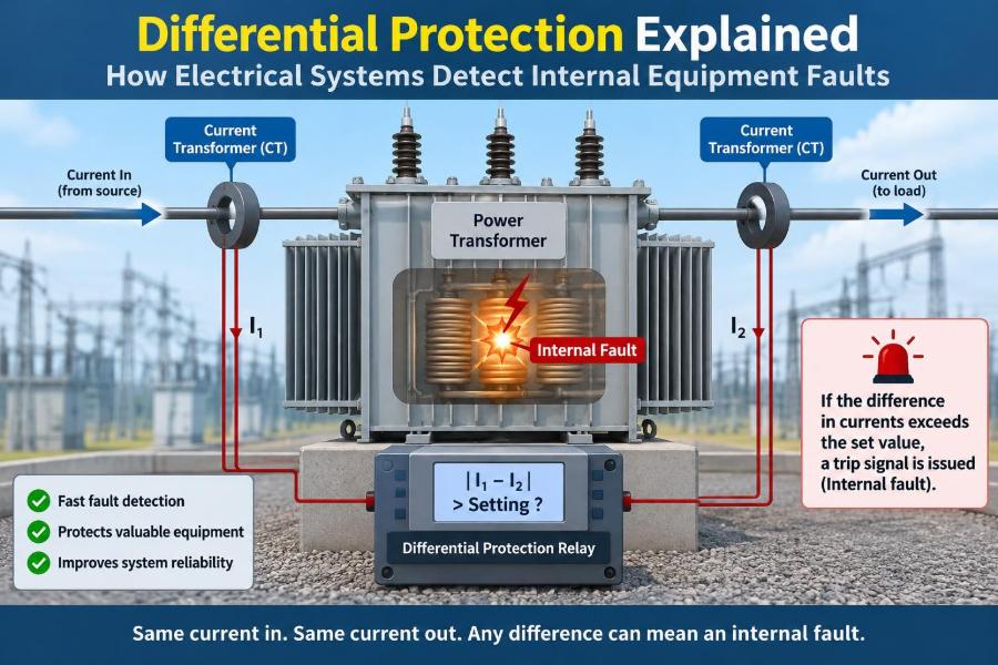
Differential protection is designed for this decision. Rather than merely noticing that current is high, it compares what enters protected equipment with what leaves it.
The idea is simple, but applying it reliably to transformers, generators, motors, busbars, and transmission lines requires careful measurement, logic, and restraint.
⚡ The Core Job of Differential Protection
Differential protection protects a defined electrical zone by comparing currents at its boundaries. Under normal conditions, and for faults outside that zone, the measured currents should balance after their directions and ratios are accounted for.
If a material difference appears, current is apparently entering a place without a matching amount leaving it. The relay interprets that imbalance as fault current within the protected zone and can trip the circuit breakers around it.
🧭 Why Fault Location Matters
Overcurrent protection responds when current exceeds a threshold. It is useful and widely applied, but it does not inherently know where the fault is. Its timing must often be coordinated with downstream devices.
Differential protection is selective: it aims to remove only the equipment containing the fault. This reduces unnecessary outages and can clear severe internal faults rapidly, before damage spreads.
🚧 Defining the Protection Zone
Every differential scheme has a protection zone, bounded physically by current transformers, usually called CTs. For a transformer, CTs may be installed on each winding side; for a busbar, they surround every connected feeder, transformer, and coupler.
The protected zone includes the conductors and equipment between those CT measurement points. A fault beyond a CT is normally an external, or through, fault. A fault between the CTs is internal.
🔄 Kirchhoff’s Current Law in Practice
The principle comes directly from Kirchhoff’s current law: the algebraic sum of currents at a node is zero. In a lossless idealized device, current entering a defined zone equals current leaving it when quantities are referred to the same basis.
Real equipment has losses and measurement errors, so relays do not demand perfect equality. Instead, they calculate a differential or operating current and decide whether it is credible evidence of an internal fault.
📏 The Two Currents a Relay Compares
Modern relays commonly use two related quantities. Operating current, also called differential current, represents the mismatch. Restraining current represents the overall current flowing through the protected item.
One common conceptual form is:
Ioperate = |I1 + I2 + ... + In|The signs reflect CT orientation and the selected current reference directions. Restraint is calculated in several relay-specific ways, often from the magnitudes of the terminal currents.
🪜 Why Biased Differential Characteristics Are Used
A fixed pickup setting alone would be too sensitive when large external-fault currents flow. Small CT errors that are insignificant at load can become substantial in amperes during a heavy through fault.
A percentage-biased, or restrained, characteristic raises the required operating current as restraint current rises. Put simply: the harder the system is pushing current through the zone, the more mismatch the relay tolerates before tripping.
| Condition | Operating current | Restraint current | Typical relay response |
|---|---|---|---|
| Normal load | Very low | Moderate | Remain stable |
| External fault | Possible CT-error mismatch | High | Restrain |
| Internal fault | High | Variable | Operate quickly |
🧲 Current Transformers Make Comparison Possible
CTs reduce primary current to standardized secondary values or sampled digital values suitable for relays. They also provide isolation from the high-energy primary circuit.
A differential scheme is only as trustworthy as its CT inputs. CT ratio, polarity, accuracy class, burden, wiring, and installation location all affect whether the relay sees a genuine imbalance or a measurement artifact.
🧷 CT Polarity and Direction Conventions
CT polarity marks identify corresponding primary and secondary directions. If one CT is wired backwards, normal load can look like fault current because the relay adds currents that should cancel.
Commissioning teams therefore verify polarity end to end, including terminal markings, drawings, relay configuration, and test-set current directions. A correct drawing does not compensate for a swapped secondary pair in the field.
📉 CT Saturation During External Faults
A CT can saturate when its magnetic core cannot reproduce a large primary current faithfully. Its secondary output then becomes distorted and reduced, particularly if the fault has a DC offset or the CT burden is excessive.
On an external fault, one saturated CT and one accurate CT can create false differential current. Biased characteristics, appropriate CT selection, short secondary leads, and carefully designed relay algorithms help maintain stability.
🛡️ Stability Is as Valuable as Sensitivity
Sensitivity means detecting small internal faults. Stability means refusing to trip for external faults, load, switching events, and measurement imperfections. Protection design is an intentional trade-off between them.
An overly sensitive relay can disconnect healthy equipment. An overly restrained relay may miss a low-level internal fault or clear it too slowly. Settings must reflect the equipment, source strength, CT performance, and credible fault conditions.
🔌 Transformer Differential Protection
Transformers are a classic application because an internal winding or bushing fault can be destructive, while ordinary load current varies continually. The relay compares currents from all protected transformer windings after converting them to a common reference.
For a two-winding transformer, this means matching the high-voltage-side current to the low-voltage-side current by the transformer ratio. Three-winding transformers need a comparison among all participating terminals.
🔢 Ratio and Phase-Shift Compensation
Transformer windings have different voltage and current magnitudes. Delta and wye connections can also introduce a phase displacement. Raw CT currents therefore cannot simply be added together.
Numerical relays apply ratio and vector-group compensation internally. Older electromechanical or static schemes often used CT connections to achieve comparable quantities. Either approach must match the actual transformer nameplate vector group and CT ratios.
🌊 Magnetizing Inrush Is Not an Internal Fault
When an unloaded transformer is energized, its core may draw a large, asymmetric magnetizing current. This inrush current enters one winding but is not transferred normally to the other, so it resembles differential current.
Tripping on every energization would be unacceptable. Many transformer differential relays recognize inrush from its waveform content, historically using harmonic restraint or blocking, and modern devices may combine this with waveform-based logic.
🎵 Harmonics Need Careful Interpretation
Inrush often contains significant second-harmonic content because of core nonlinearity. A relay can use that feature to restrain the differential element while inrush is present.
Harmonic methods are helpful, not magical. Modern core materials, residual flux, system conditions, and internal-fault waveforms can complicate the pattern. Settings and algorithms should follow the relay manufacturer’s guidance and the specific application study.
🔥 Overexcitation and Other Transformer Conditions
Excessive volts-per-hertz can drive a transformer core toward saturation, creating high magnetizing current and harmonics. This is an abnormal operating condition, but it is not necessarily a winding fault requiring instantaneous differential tripping.
Transformer protection is therefore layered. Differential protection works alongside volts-per-hertz protection, sudden-pressure or gas-operated devices where fitted, overcurrent elements, temperature monitoring, and mechanical safeguards.
⚙️ Generator Differential Protection
A generator differential scheme compares currents at the machine terminals and neutral end of each stator winding. It is intended to detect phase and ground faults within the stator zone.
Ground-fault coverage depends on grounding arrangement and the fault’s location along the winding. Differential protection is powerful for high-current internal faults, but it may not alone detect every low-current turn-to-turn or ground fault scenario.
🏭 Motor Differential Protection
Large motors may justify differential protection because internal stator faults can develop rapidly and replacement can be disruptive. CTs at the supply end and, where accessible, the neutral end provide the two boundary measurements.
Smaller motors are commonly protected by overload, short-circuit, earth-fault, and thermal functions instead. The decision depends on motor rating, criticality, available terminals, and whether neutral-end CT installation is practical.
🚌 Busbar Differential Protection
A busbar ties many circuits together, so a bus fault must usually be cleared with exceptional speed. Bus differential protection sums the currents from every connected circuit: for healthy operation, the vector sum is close to zero.
Bus schemes must also know which isolators and circuit breakers are open or closed. This topology information lets the relay assign each CT to the correct bus section in stations with transfer buses, sectionalizers, or complex switching arrangements.
📡 Line Current Differential Protection
For a transmission or distribution line, relays at both ends compare currents using a communications channel. The protected zone is the line between the terminal CTs.
Unlike distance protection, line differential does not infer location from voltage and impedance. It directly compares terminal current data, but its dependability relies on synchronized data handling and a suitably reliable communications path.
🧩 Low-Impedance and High-Impedance Designs
Most modern numerical schemes are low-impedance differential systems. They calculate operating and restraint currents, apply slopes, and can incorporate sophisticated supervision.
High-impedance differential protection is a different design philosophy, often used for restricted earth fault and some bus applications. It uses matched CT behavior, a stabilizing resistor, and a high relay impedance to remain stable during external faults. It must be engineered as a complete circuit, not assembled from interchangeable assumptions.
🌍 Restricted Earth Fault Protection
Restricted earth fault, or REF, protects a limited zone against ground faults. It compares residual current from phase CTs with current measured in the neutral connection.
REF can be very sensitive to winding-to-earth faults near a grounded transformer neutral, where phase differential current may be modest. It complements transformer differential protection rather than replacing it, because its coverage is deliberately narrower.
⏱️ Why Differential Protection Can Be Fast
Because it compares currents at the zone boundary, differential protection generally does not need deliberate time grading with protective devices outside the zone. A valid internal fault can therefore initiate rapid tripping.
Actual clearing time still includes relay processing, output contacts or communications, breaker operating time, and arc extinction. Protection engineers evaluate the whole clearing chain, especially for equipment with limited fault withstand capability.
🔗 Tripping Every Source Around the Fault
An internal fault remains energized if only one source is disconnected while another continues feeding it. Differential tripping logic must identify and open all breakers that can supply fault current into the zone.
For example, transformer differential protection may trip breakers on both voltage sides and initiate lockout logic. Generator or bus schemes can involve multiple breakers, intertrips, and breaker-failure backup actions.
🧠 Numerical Relays Add Useful Supervision
Digital relays sample currents, calculate phasors or waveform features, and apply multiple logic checks. They can provide event records, oscillography, metering, alarms, and communications alongside protection.
These capabilities aid diagnosis, but complexity adds responsibilities: firmware control, configuration review, cybersecurity practices, time synchronization where relevant, and disciplined management of setting changes.
🧪 Testing Proves the Complete Scheme
Testing is more than injecting current into a relay input. A meaningful program checks CT polarity and ratio, secondary wiring, relay logic, trip paths, breaker actions, alarms, and records.
Primary injection or other end-to-end methods can reveal errors that isolated secondary injection may not. The appropriate tests depend on the installation, outage constraints, safety procedures, and the owner’s maintenance strategy.
🗂️ Settings Depend on a Real Protection Study
Pickup values, bias slopes, harmonic restraint, CT assumptions, and trip logic cannot be copied safely from a similar-looking project. They come from a coordinated protection study using the actual equipment data and system operating conditions.
Engineers consider maximum load, minimum and maximum fault levels, transformer vector groups, CT excitation behavior, grounding, feeder contributions, and required backup protection. Any major network change can justify reviewing those assumptions.
⚠️ Common Application Mistakes
Many differential problems originate in engineering details rather than relay hardware. Frequent mistakes include:
- Incorrect CT polarity or phase association.
- Applying the wrong transformer vector-group compensation.
- Using CTs that saturate excessively for available through-fault duty.
- Leaving a CT secondary circuit open, which can create hazardous voltage.
- Defining zone boundaries inconsistently across drawings, settings, and wiring.
- Assuming harmonic blocking will cover every non-fault transient.
These errors are preventable through independent design review, controlled drawings, commissioning tests, and clear change management.
🧰 What Differential Protection Does Not Replace
No single function covers every failure mode. Differential protection may not detect insulation deterioration before it faults, all interturn faults, external overloads, abnormal frequency, or every low-level earth fault.
Reliable systems use coordinated layers: differential elements for internal faults, overcurrent or distance functions for external faults, thermal protection for heating, and condition monitoring for developing issues. Each layer covers limitations in the others.
🧑🏫 A Simple Transformer Fault Example
Consider a hypothetical transformer with CTs on its high- and low-voltage sides. During normal load, the relay’s compensation makes the two measured currents equal and opposite, so operating current remains low.
Now suppose an arc develops inside the protected winding section. Both sources may feed the arc, but their boundary currents no longer balance. Operating current rises beyond the restrained characteristic, and the scheme trips the breakers that isolate the transformer.
By contrast, a fault on a feeder beyond the low-voltage CT produces high current through the transformer but should remain balanced at the differential boundaries. The relay restrains while the feeder’s own protection clears the fault.
🧭 Reading an Event Record After a Trip
An event record can help distinguish a true internal event from a wiring or CT problem. Engineers examine phase currents, differential and restraint quantities, harmonic indicators, binary inputs, trip outputs, breaker status, and the sequence of events.
A trip record is evidence, not automatic proof. Investigation should also include equipment inspection, insulation testing where appropriate, CT circuit checks, and a review of switching conditions before any return to service.
✅ The Principle to Remember
Differential protection turns a practical question into a measured comparison: does the current entering this defined zone match the current leaving it? When the answer is no by enough margin, and the relay’s security checks support that conclusion, it isolates the equipment.
Its value comes from speed and selectivity, but those strengths rest on correct CTs, correct compensation, sensible settings, complete tripping, and rigorous testing. The relay is not merely watching high current; it is accounting for current at the boundaries of an electrical asset.
Well-designed differential protection detects internal faults by measuring imbalance, while remaining stable when the fault is outside the equipment it protects. That balance is why it remains one of the most trusted principles in power-system protection. ⚡🛡️🔌