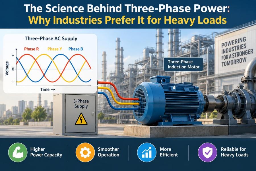

A factory conveyor starts moving, a refrigeration compressor settles into a steady hum, and a large pump begins pushing water through a treatment plant. None of these loads would be easy to run from the kind of single-phase outlet found in a typical home.
The difference is not simply that industrial sites use “more electricity.” Their electrical systems deliver power in a different form: three-phase AC power. It is designed to transfer substantial energy smoothly, operate large motors effectively, and distribute power with practical conductor sizes.
Three-phase power is behind much of the machinery that makes modern life work: elevators, data-center cooling equipment, machine tools, quarry crushers, commercial HVAC systems, and production lines. Understanding its behavior explains why it became the standard for heavy-duty electrical work.
The idea can initially sound abstract: three voltage waveforms, displaced in time, sharing a supply. But its central advantage is intuitive. Rather than delivering energy in large pulses, a balanced three-phase system delivers it almost continuously.
⚡ What “Three-Phase” Actually Means
Alternating current, or AC, repeatedly reverses direction. Its voltage is usually represented as a sine wave because the voltage rises smoothly from zero to a positive peak, returns through zero, reaches a negative peak, and repeats.
A three-phase supply contains three AC voltages of the same frequency and magnitude, timed 120 electrical degrees apart. These voltages are commonly called phases A, B, and C, although conductor labels vary by region and installation.
When phase A is at its positive peak, phases B and C are at different points in their cycles. The staggered timing is the feature that creates three-phase power’s smooth combined output.
🌊 A Better Analogy Than “Three Times the Power”
It is tempting to imagine three-phase power as three independent household circuits. That picture misses the main point. The phases are related waveforms produced and managed together by an alternator, transformer, or inverter.
Imagine three people pushing a heavy carousel at evenly spaced points. If they coordinate their pushes, the carousel receives force throughout its rotation rather than one hard shove followed by a pause. Three-phase power similarly supplies rotating machines with a more nearly continuous turning effect.
Its capacity depends on voltage, current, equipment ratings, and system design. The defining advantage is not automatically “three times” anything; it is the balanced, time-shifted delivery of energy.
🔄 Why Phase Separation Is 120 Degrees
Three equal phase intervals must fill one complete electrical cycle. Dividing 360 degrees by three gives 120 degrees. This even spacing makes the three phase voltages symmetrical in a balanced system.
At any instant, one phase may be increasing while another is decreasing and the third is near an opposite extreme. The algebraic relationship among the three sinusoidal quantities gives useful cancellation effects in balanced circuits.
This symmetry also lets a three-phase machine create a magnetic field that rotates naturally. That result is central to industrial motor operation.
📈 The Key Advantage: Nearly Constant Power
With a simple single-phase resistive load, instantaneous power rises and falls during every AC cycle. Its average may be useful, but the energy transfer is not perfectly steady moment by moment.
In a balanced three-phase load, the individual phase powers vary, but their sum is essentially constant. One phase compensates for the others as their sine waves progress.
This matters most for motors. A steadier power input produces smoother torque, less torsional pulsation, and more stable mechanical operation. Pumps, compressors, conveyors, and machine spindles benefit from that smoothness.
🧲 How Three Phases Create a Rotating Magnetic Field
Place three stator windings around a motor and feed each one with a phase shifted by 120 degrees. Each winding produces a magnetic field whose strength and direction vary with its AC current.
Because the currents peak in sequence, the combined magnetic field appears to rotate around the stator. A rotor responds to this moving field, producing torque without needing the special starting arrangement typical of many single-phase motors.
This is a physical, not merely mathematical, advantage. The electrical timing becomes a useful rotating force inside the machine.
🏭 Why Induction Motors Thrive on Three-Phase Supply
The three-phase induction motor is widely used because it is mechanically simple and robust. Its rotor can be a conductive cage-like structure rather than a rotor requiring brushes, commutators, or permanent electrical connections in many common designs.
The rotating stator field induces current in the rotor. Interaction between rotor current and the stator field creates torque. The rotor turns slightly slower than the rotating field; that speed difference is called slip, and it is necessary for induction to occur.
A three-phase induction motor is generally self-starting because the stator field already rotates at startup. A conventional single-phase induction motor, by contrast, needs an auxiliary winding, capacitor, switch, or other method to establish a starting field.
🛠️ Starting Torque and Heavy Mechanical Loads
Heavy loads often require substantial torque before they move. A loaded conveyor, positive-displacement pump, or compressor may have friction, fluid pressure, or material weight resisting the first rotation.
Three-phase motor designs can provide dependable starting characteristics suitable for industrial duty when selected and controlled correctly. The system’s rotating field avoids the zero-torque standstill condition that a purely pulsating single-phase field would present.
That does not mean every three-phase motor can start every load directly across the line. Load inertia, required breakaway torque, supply capacity, and the chosen starting method must all be evaluated.
⚙️ Speed, Frequency, and Pole Count
The rotating magnetic field’s speed is called synchronous speed. It is determined by supply frequency and the number of magnetic poles built into the motor stator.
More poles produce a lower synchronous speed at the same frequency. This is why motors can be designed for different nominal speed ranges without relying entirely on gears.
Induction motors run below synchronous speed under load because of slip. In practice, the actual shaft speed also changes modestly as load changes, a consideration for processes requiring close speed regulation.
🎛️ Variable-Frequency Drives Change the Picture
A variable-frequency drive, or VFD, first converts incoming AC to DC and then electronically synthesizes a controlled three-phase output. By changing output frequency, it changes the rotating field speed and therefore the motor’s operating speed.
VFDs allow controlled acceleration, process-speed adjustment, and reduced mechanical shock in many applications. A fan or pump, for example, may be operated at the speed the process needs rather than continuously throttled or damped.
Drives introduce their own design concerns: harmonic currents, electromagnetic interference, cable effects, motor insulation stress, and grounding practices. They are powerful tools, not plug-in solutions to every motor problem.
🔌 Line Voltage Versus Phase Voltage
Three-phase systems use two related voltage terms. Line voltage is measured between any two line conductors. Phase voltage is the voltage across one phase winding or phase load, and its relationship to line voltage depends on the connection.
Confusing these values is a common source of incorrect equipment selection. A motor nameplate, transformer secondary, and facility distribution label must be read in the context of the system configuration.
Electrical work should never rely on assumptions based on plug shape, wire color, or a remembered voltage value. Verification procedures and competent measurement are essential.
⭐ The Wye Connection
In a wye, also written star, one end of each phase winding joins at a common point called the neutral point. The three remaining ends connect to the line conductors.
A neutral conductor may be brought out from that common point. This makes a wye system useful where a facility needs both three-phase equipment and line-to-neutral single-phase loads such as lighting, controls, or receptacle circuits.
For a balanced wye system, line voltage is greater than phase voltage by a factor of the square root of three. The line current equals the phase current.
🔺 The Delta Connection
In a delta connection, the three phase windings connect end-to-end in a closed triangle. Each junction connects to one line conductor, and there is normally no neutral point inherent in the basic delta arrangement.
For a balanced delta system, line voltage equals phase voltage. Line current is greater than phase current by the square root of three because each line feeds two phase branches.
Delta configurations are commonly associated with three-phase motor loads and certain transformer applications. The correct choice depends on voltage needs, grounding method, load mix, protection, and local system practice.
📊 Wye and Delta at a Glance
| Feature | Wye (Star) | Delta |
|---|---|---|
| Basic shape | Three windings meet at a common point | Three windings form a closed loop |
| Neutral availability | Often available | Not inherent in the basic connection |
| Balanced voltage relationship | Line voltage = √3 × phase voltage | Line voltage = phase voltage |
| Balanced current relationship | Line current = phase current | Line current = √3 × phase current |
| Typical practical role | Mixed line-to-line and line-to-neutral loads | Three-phase loads and transformer arrangements |
These relationships describe ideal balanced sinusoidal systems. Real installations may include unbalance, harmonics, transformer phase shifts, and grounding arrangements that require more detailed analysis.
📐 The Three-Phase Power Formula
For a balanced three-phase AC system, real power is commonly calculated as P = √3 × VLL × IL × PF. Here, VLL is line-to-line RMS voltage, IL is line current, and PF is power factor.
Real power, measured in watts, is the part that performs useful work or becomes heat. The square-root-of-three factor comes from the geometry of the balanced phase quantities.
For example, a balanced motor drawing line current at a known line voltage does not have its real power found by simply multiplying voltage and current. Power factor must be included, and actual operating measurements may differ from nameplate conditions.
🧮 Apparent, Real, and Reactive Power
AC systems must handle more than real power. Apparent power, measured in volt-amperes (VA), is the voltage-current product that sizes much of the electrical infrastructure. Reactive power, measured in var, supports electric and magnetic fields but does not become net useful work over a full cycle.
Motors, transformers, and other inductive equipment require magnetizing current. That current affects conductor loading even when it is not producing proportional mechanical output.
Power factor expresses the relationship between real power and apparent power under sinusoidal conditions. A lower power factor means more current is required to deliver the same real power at a given voltage.
📏 Why Three-Phase Uses Conductors Efficiently
For a given amount of transmitted power and a given voltage class, a balanced three-phase system can use conductor material more effectively than an equivalent single-phase arrangement. Its phases share the task continuously and symmetrically.
This advantage becomes significant in feeders, busways, transformers, switchgear, and large motor circuits. Lower current for a given power at a higher appropriate voltage can also reduce resistive loss, which rises with the square of current.
“More efficient” does not mean losses disappear. Conductors still heat, connections still have resistance, and poor design can waste substantial energy in any system.
🌡️ Current, Heating, and Voltage Drop
Every conductor has resistance. When current flows, it creates heating proportional to the square of current times resistance. This is why high-current circuits need careful conductor sizing, termination quality, and thermal planning.
Long runs also experience voltage drop. Excessive drop can reduce motor starting torque, increase current during difficult starts, and cause contactors or control equipment to behave unpredictably.
Engineers account for conductor material, length, installation method, ambient temperature, grouping, protective-device coordination, and expected duty cycle. Ampacity tables alone do not replace a complete design review.
🏗️ Distribution From Utility to Machine
A typical industrial power path may include utility service equipment, transformers, main switchgear, feeders, motor control centers, branch protection, starters or drives, and finally the motor or process equipment.
Each stage has a job. Transformers establish useful voltage levels, switchgear isolates and protects sections of the system, and motor control equipment starts, stops, and protects individual machines.
The strength of three-phase distribution is that one common supply architecture can support many large loads while remaining scalable. A facility can divide loads among panels and feeders instead of building a separate generation source for every machine.
🚚 Real Loads That Favor Three-Phase Power
Three-phase supply is especially well suited to loads with significant continuous power demand, rotating inertia, or high starting requirements. Common examples include:
- Large pumps for water, irrigation, process fluids, and fire-protection systems
- Fans and blowers in ventilation and industrial air handling
- Refrigeration and chiller compressors
- Conveyors, hoists, mixers, crushers, and machine tools
- Welders, rectifiers, furnaces, and other high-capacity process equipment
Not every item in an industrial building needs three-phase power. Controls, computers, small appliances, and lighting may use single-phase circuits supplied from a suitable three-phase distribution system.
🏠 Why Homes Usually Use Single-Phase Service
Homes generally have smaller and more intermittent loads. Lighting, electronics, kitchen appliances, and modest HVAC equipment can be served economically by residential single-phase arrangements.
Single-phase motors are acceptable for many household applications, particularly where power is limited and simplicity at the appliance level matters. A small fan does not need the same motor system as a production-line conveyor.
Some larger residences or specialized properties may have three-phase service, but it is not automatically worthwhile. Service availability, equipment demand, installation cost, and local utility arrangements all matter.
🔀 Phase Balance Is Not Optional
A balanced three-phase load draws similar current on all three phases with the expected phase displacement. Motors are naturally close to balanced when healthy and supplied correctly.
Facilities also connect many single-phase loads to a three-phase system. If too many are placed on one phase, that phase can become overloaded while the others remain lightly loaded. Voltage imbalance can follow.
Good distribution planning tracks phase loading and revisits it as equipment changes. Balanced current improves equipment utilization and reduces avoidable stress on conductors and transformers.
⚠️ Voltage Unbalance Can Damage Motors
Even a relatively small voltage unbalance can produce a larger current unbalance in a three-phase motor. The uneven currents create extra heating and may reduce available torque.
Possible causes include unequal single-phase loading, poor connections, a failing fuse or pole, transformer problems, or supply issues. The symptom may be overheating, nuisance overload trips, abnormal sound, or shortened insulation life.
The correct response is diagnosis, not simply increasing overload settings. Raising protection thresholds can conceal a fault while allowing the motor to operate in a damaging condition.
🧯 Protection Is More Than a Circuit Breaker
Short-circuit and ground-fault protection interrupts severe fault current. Motor overload protection responds to sustained overcurrent that can overheat windings. These are different hazards and often require coordinated devices.
Motor circuits may also use phase-loss protection, under-voltage protection, thermal sensors, and drive fault monitoring. The right combination depends on the motor, process risk, control method, and applicable electrical rules.
Protection settings must match the actual equipment and conductor ratings. Incorrect settings can cause nuisance trips, failed starts, inadequate protection, or unsafe fault behavior.
🚨 Phase Loss and Single-Phasing
If one phase opens because of a blown fuse, failed contact, damaged conductor, or loose connection, a running three-phase motor may continue turning. This condition is called single-phasing.
The remaining phases can draw excessive current while the motor develops less torque. If the mechanical load remains high, overheating can occur rapidly enough to damage insulation.
A motor that will not start after losing a phase usually draws very high current and should be disconnected promptly. Proper overload protection and phase-monitoring devices reduce risk, but routine inspection of terminations remains valuable.
🧰 Starting Methods Must Match the Load
Direct-on-line starting applies full supply voltage to a motor and can provide a brisk start, but it also produces high inrush current. That may be acceptable for some small or stiff supply systems and unsuitable for others.
Reduced-voltage starters, soft starters, and VFDs provide alternatives. Soft starters limit voltage during acceleration, while VFDs additionally control frequency and can shape the speed profile more broadly.
Selecting a starter involves more than reducing electrical demand. Consider required starting torque, acceleration time, process behavior, supply voltage drop, mechanical stress, and whether the machine needs variable speed after startup.
🔧 Maintenance Clues in Three-Phase Equipment
Routine electrical maintenance often looks for changes rather than dramatic failures. Comparing phase currents under similar operating conditions can reveal imbalance, a developing mechanical problem, or a supply issue.
Loose lugs and worn contacts create resistance, which creates heat. Thermographic inspections, torque checks performed according to equipment requirements, and visual checks for discoloration can help identify poor connections.
Motor condition also depends on bearings, cooling airflow, alignment, and driven-load condition. Electrical readings should be interpreted alongside mechanical evidence.
📟 Measuring Safely and Meaningfully
Measuring a three-phase system may involve line-to-line voltage, line-to-neutral voltage where a neutral exists, phase current, real power, power factor, frequency, and waveform quality. A meter reading is useful only when the measurement points and expected values are understood.
Live electrical work presents arc-flash and shock hazards. Only qualified people using appropriate procedures, rated instruments, and protective equipment should perform energized diagnostic work.
For troubleshooting, record readings across all phases under comparable load conditions. One isolated current value is often less informative than a clear three-phase comparison.
🌐 Harmonics and Modern Nonlinear Loads
Drives, rectifiers, switched-mode power supplies, and LED drivers do not always draw a smooth sinusoidal current. They can create harmonic currents: components at multiples of the fundamental frequency.
Harmonics can add heating, affect transformer and conductor loading, interfere with sensitive equipment, and complicate power-factor interpretation. In four-wire systems, certain harmonic components can accumulate in the neutral rather than canceling as ideal balanced fundamental currents do.
Mitigation may include appropriate drive input reactors, filters, transformer selection, conductor design, and measurement with instruments capable of assessing distorted waveforms. The best approach depends on the installation, not a generic add-on.
🔋 Power Factor Correction Has Limits
Capacitors can supply reactive power locally for inductive loads, improving displacement power factor in suitable systems. This can reduce upstream current and release capacity in conductors or transformers.
But capacitor banks must be designed carefully. Switching transients, resonance with system inductance, load variation, and harmonic distortion can create problems when correction is applied casually.
Facilities with significant nonlinear loads often need a harmonic-aware assessment before adding capacitors. Improving one electrical metric is not useful if it introduces overheating or voltage distortion elsewhere.
🗺️ Frequency and Regional System Differences
Three-phase principles are universal, but nominal voltages, frequency, grounding conventions, conductor identification, and protection practices differ by country and utility system. Equipment made for one market may not be directly suitable for another.
Frequency affects motor synchronous speed and transformer behavior. Voltage affects insulation requirements, current, and equipment ratings. A motor nameplate must be checked for permitted voltage and frequency combinations before connection.
When working across regions, use the applicable local electrical code and manufacturer documentation rather than assuming familiar practices transfer unchanged.
🧠 Common Misconceptions to Leave Behind
- “Three-phase means three times the voltage.” No. The voltage relationship depends on the measurement and connection configuration.
- “A neutral is always needed.” Balanced three-phase loads can operate with three line conductors only.
- “Any three-phase motor can run on any three-phase supply.” Nameplate voltage, frequency, connection, grounding, and control compatibility matter.
- “More phases automatically eliminate losses.” Three-phase systems are efficient, but conductors, transformers, motors, and power electronics still have losses.
- “A breaker alone fully protects a motor.” Motor overload, phase-loss, and process-specific protection may also be required.
🧩 Choosing Between Single-Phase and Three-Phase
The appropriate supply is based on the load, not prestige. A small intermittent appliance may be best served by single-phase power. Adding three-phase infrastructure for it would offer little practical benefit.
Three-phase becomes compelling when a site has large motors, numerous motor loads, high continuous demand, long distribution runs, or a need for robust variable-speed control. Commercial kitchens, workshops, farms, and process facilities may fall anywhere along this spectrum.
A proper decision considers present demand, expected expansion, available utility service, fault capacity, installation cost, maintenance capability, and the characteristics of the actual equipment.
✅ The Core Principle Behind Industrial Preference
Industries favor three-phase power because three evenly timed AC waveforms combine into a practical system for moving large amounts of energy. The result is nearly constant power transfer, a naturally rotating motor field, efficient distribution, and flexible equipment options.
Its advantages are strongest when the system is balanced, correctly rated, properly protected, and matched to the mechanical process. Three-phase power is not magic; it is a highly effective engineering arrangement whose benefits depend on sound design and maintenance.
From the utility transformer to the motor shaft, every part of the installation uses the same principle: coordinated phases can do steady work more effectively than a single pulsating source.
Three-phase power became the industrial standard because it turns carefully timed electrical waves into smooth, controllable, and scalable mechanical power. Once that connection is clear, the hum of a large motor sounds less mysterious—and much more purposeful. ⚡🏭🔄