
A neighborhood loses power during a storm. Within seconds, some homes see lights flicker back on while a few blocks remain dark. At the utility control center, no operator is driving through the rain to inspect every pole. Software, sensors, communications networks, and protective devices are already reporting what happened and isolating the likely fault.
The same invisible coordination is at work on an ordinary sunny afternoon. Electricity must be generated, transmitted, distributed, and consumed at nearly the same instant. Unlike water in a reservoir, large-scale electrical energy has limited storage in most grids, so imbalance has consequences quickly.
Smart power systems make this balancing act more observable and controllable. They help operators see equipment status, protection systems clear dangerous faults, and grid-control applications keep voltage and frequency within acceptable operating ranges.
Understanding these systems matters for electrical engineers because modern power work increasingly sits at the boundary of power apparatus, automation, communication networks, and cybersecurity. The “software” is not separate from the grid; it is part of how the grid is operated safely.
⚡ A power grid is a real-time physical system
A power system includes generators, transformers, transmission lines, substations, distribution feeders, loads, and increasingly batteries and distributed energy resources. Its behavior is governed by electrical laws, but its operation depends on decisions made continuously.
Generation and demand must remain closely balanced. If demand suddenly exceeds generation, system frequency tends to fall. If generation exceeds demand, frequency tends to rise. Voltage also changes with reactive-power conditions, line loading, transformer tap settings, and local network characteristics.
Software does not repeal those physical constraints. It gives people and automated controllers a faster, more coherent view of them.
🧠 What “smart” means in a power system
A smart grid is not one product or one control room screen. It is an operational approach that combines measurement, communication, analysis, and action across the electrical network.
Traditional equipment can operate safely with local electromechanical or digital protection. Smart capabilities add richer data, remote control, automated restoration, forecasting, coordinated distributed resources, and better asset awareness.
Smart does not mean fully autonomous. Many actions remain intentionally supervised by trained operators, especially when consequences are broad, uncertain, or safety-critical.
🗺️ The operational layers behind the screen
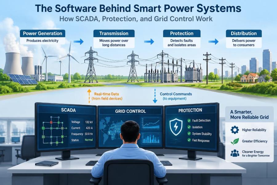
A useful way to understand grid software is to separate it into layers. Field equipment measures and switches the physical system; station systems collect and process local information; control-center applications coordinate a wider area.
| Layer | Main role | Typical examples |
|---|---|---|
| Field | Sense and act on electrical equipment | CTs, VTs, breakers, relays, sensors |
| Substation or site | Concentrate data and execute local automation | IEDs, bay controllers, RTUs, gateways |
| Control center | Monitor, analyze, dispatch, coordinate | SCADA, EMS, DMS, historian |
| Enterprise and planning | Support maintenance, markets, and planning | Asset systems, forecasting, analytics |
These layers overlap in practice, but the distinction prevents a common misunderstanding: a control-room application is only one part of a complete control system.
🖥️ SCADA: the grid’s supervisory nervous system
SCADA stands for Supervisory Control and Data Acquisition. It gathers measurements and equipment states from remote locations, displays them to operators, records events, produces alarms, and permits selected remote commands.
“Supervisory” is a key word. A SCADA system may tell a remote terminal unit to open a breaker, but the fast fault-clearing decision is usually made locally by protection devices. SCADA is designed for broad visibility and operational coordination, not as a substitute for every local safety function.
A SCADA display commonly shows one-line diagrams: simplified representations of buses, transformers, lines, switches, and breakers. Colors and symbols indicate energized state, open or closed status, alarms, and measurements.
📡 From voltage and current to usable data
High-voltage quantities cannot be connected directly to ordinary electronics. Current transformers, or CTs, scale line current to a measurable level. Voltage transformers, often called VTs or potential transformers, provide a reduced, isolated representation of system voltage.
Intelligent electronic devices, or IEDs, use these inputs to calculate values such as current, voltage, power, frequency, and phase angle. They also receive contact states from breakers, disconnectors, transformer alarms, and other devices.
Measurement quality matters. A stale, incorrectly scaled, or badly time-stamped value can lead an operator or application to draw the wrong conclusion, even when the communication link itself is functioning.
🔌 Remote terminal units and intelligent devices
An RTU, or remote terminal unit, traditionally gathers local status points, analog values, and control signals, then sends them to a central SCADA system. RTUs remain common, particularly in remote substations and distribution sites.
Modern IEDs may perform much of this work themselves while also providing protection, control logic, disturbance records, and communication services. A substation gateway often aggregates information from multiple IEDs and presents it to external systems.
The practical question is not which device has the more fashionable name. It is which architecture provides dependable control, clear ownership of logic, maintainable engineering files, and useful diagnostics.
🧾 The point model: translating equipment into signals
SCADA sees the grid through a point model. Each point represents a value or condition: breaker 52A closed, feeder current, transformer oil temperature alarm, tap position, or a command permissive.
Points have meaning beyond their raw number. A current value needs units, scaling, quality flags, engineering limits, and an identifier tied to the correct asset. A breaker indication may need separate open and closed contacts so invalid combinations can be detected.
Poor point naming and inconsistent conventions become expensive during alarms, troubleshooting, and future expansion. Clear data modeling is therefore an engineering safety measure, not merely documentation work.
⏱️ Why time synchronization changes diagnosis
When a disturbance crosses several substations, event order matters. Did a line trip before a transformer overload alarm? Did a breaker fail to open after a relay issued a trip? Without synchronized clocks, records may appear in an impossible sequence.
Time synchronization aligns IEDs, RTUs, recorders, and control-center systems to a common reference. Different applications require different precision, but protection-event investigation generally demands much better alignment than routine meter reporting.
Accurate timestamps turn isolated logs into a sequence of evidence. They are indispensable after faults, misoperations, communications interruptions, and cybersecurity investigations.
🗣️ Communication protocols make devices interoperable
Power devices need agreed rules for exchanging data. These rules, called communication protocols, define how points are represented, how messages are structured, and how devices request or report information.
Common protocol families include IEC 61850 within substations, DNP3 in many utility telemetry applications, and IEC 60870-5 variants in other regions. Their suitability depends on system design, installed equipment, performance needs, and organizational standards.
Interoperability is never automatic simply because two products claim protocol support. Engineers must verify data types, quality indications, control behavior, time handling, network configuration, and failure responses.
🔄 Polling, reporting, and event-driven data
In polling, a master system periodically asks field devices for data. It is simple to understand and remains useful, but frequent polling consumes bandwidth and may delay awareness of a rapid change.
In report-by-exception or event-driven designs, a device sends information when a value changes or crosses a configured threshold. Modern substation systems can also exchange certain time-critical messages directly between devices.
The best approach is usually mixed. Operators need periodic values to confirm communication health, while alarms and changes of state should reach them promptly without waiting for the next routine scan.
🧯 Protection is not the same as grid control
Protection exists to detect faults or abnormal conditions and remove the affected equipment quickly enough to limit damage and preserve system stability. Grid control manages normal and abnormal operation at a broader timescale.
A protection relay can detect an internal transformer fault and trip associated breakers in milliseconds or cycles, depending on the scheme and equipment. A control-center operator may then assess the outage, reconfigure the network, and coordinate repair.
Protection prioritizes speed and selectivity; supervisory control prioritizes system-wide awareness and coordination. Confusing these roles leads to unsafe expectations of communications-dependent automation.
🛡️ How protective relays recognize trouble
Protective relays compare electrical measurements against protection logic. An overcurrent element operates when current exceeds a threshold with a configured time characteristic. A distance element estimates apparent impedance to identify faults along a transmission line.
Differential protection compares currents entering and leaving a protected zone. Under normal conditions, their vector sum is approximately balanced after proper compensation. A significant difference can indicate an internal fault.
Relays also use logic based on voltage, frequency, direction of power flow, breaker position, and communications signals. Modern digital relays are sophisticated computers, but their settings must reflect the actual power-system design.
🎯 Selectivity: clearing only what needs to be cleared
A fault should be isolated as close to its location as practical. This principle is called selectivity or coordination. A downstream feeder fault should normally trip the feeder breaker, not disconnect an entire substation.
Backup protection is still necessary because breakers, sensors, relay logic, and communication channels can fail. The backup device may operate more slowly or disconnect a larger portion of the network, but it provides another path to clear danger.
Coordination studies examine fault levels, relay curves, breaker ratings, transformer connections, and network configurations. Adding generation or changing a feeder arrangement can alter these assumptions substantially.
🚨 Breakers are the muscles of protection
A relay makes a decision; a circuit breaker interrupts the fault current. Opening a high-voltage circuit under fault conditions requires managing an electrical arc, so breakers are specialized pieces of power apparatus, not just oversized switches.
Protection schemes monitor whether a breaker actually operated. Breaker-failure logic can initiate backup tripping if current continues after a trip command and the expected position change does not occur.
SCADA may display a breaker as open or closed, but protection relies on hardwired or engineered local signals with known timing and integrity. A display update is not proof that a breaker has interrupted fault current.
🌐 Transmission control and system stability
Transmission networks move large amounts of power across long distances. Operators must manage thermal line limits, voltage profiles, generator output, reactive-power resources, and credible equipment outages.
A disturbance can trigger changing flows elsewhere in the network. For example, losing one line may redirect power onto parallel paths. If those paths overload or voltage support is inadequate, additional trips can worsen the event.
Energy management system, or EMS, applications help transmission operators monitor the network and assess operating conditions. Their outputs support decisions; they do not remove the need for operating procedures and engineering judgment.
📉 Frequency control keeps generation and demand aligned
Grid frequency reflects the balance between real-power generation and load. A sudden generator loss tends to lower frequency because remaining machines and other responsive resources supply the deficit briefly through stored rotational energy or controls.
Fast local governor response, battery controls, and other frequency-responsive resources can help arrest the change. Slower dispatch actions then restore reserves and bring frequency toward its scheduled value.
If frequency falls too far, underfrequency load shedding may disconnect selected loads to prevent a broader collapse. This is a last-resort protective action, carefully engineered for the particular system rather than a routine control tool.
🔋 Voltage control is largely a reactive-power problem
Voltage is influenced by reactive power, network impedance, transformer taps, load behavior, and equipment operating limits. Real power is measured in watts; reactive power, measured in vars, supports electric and magnetic fields needed by many AC-system devices.
Generators, capacitor banks, reactors, static compensation equipment, and inverter-based resources can contribute to voltage regulation. On distribution systems, voltage regulators and capacitor controls may act locally according to voltage, current, time, or communications commands.
Raising voltage everywhere is not a solution. Excessive voltage can damage customer equipment or violate operating limits, while low voltage can increase current for some loads and create additional problems.
🧮 State estimation turns measurements into a network picture
No control center measures every electrical quantity at every location. Telemetry can be missing, erroneous, delayed, or inconsistent with a modeled breaker state. State estimation uses measurements and a network model to calculate a plausible, internally consistent system state.
The process can identify suspicious data, but it is not magic. A wrong model, unobserved network change, or insufficient measurement coverage can reduce confidence in the result.
For operators, a reliable estimated state is more useful than a cluttered collection of raw values because it connects individual measurements to the behavior of the whole network.
🔍 Contingency analysis asks “what if?”
Contingency analysis studies how the system might respond if a credible component is lost, such as a line, transformer, or generator. It estimates possible overloads, voltage issues, and other limit violations under those scenarios.
Operators can use results to adjust dispatch, switch equipment, defer maintenance, or prepare corrective actions before an outage occurs. The assessment depends on assumptions about loading, available generation, protection behavior, and network topology.
It is a planning-and-operations tool, not a prediction that a component will fail. Its value lies in preparing for consequences that are technically possible.
🏘️ Distribution management changes the view downstream
Distribution management systems, or DMS platforms, focus on medium- and low-voltage networks closer to customers. These networks were historically less observable than transmission systems, but automated switches, smart meters, sensors, and feeder devices are expanding visibility.
A DMS may support feeder loading analysis, voltage optimization, outage management, switching plans, and restoration. It must account for radial feeders, normally open ties, protection coordination, and the fact that a circuit can be energized from more than one possible source after switching.
Distribution data is often less complete and more variable than transmission data. Good operational tools show uncertainty rather than pretending every field condition is known.
🔁 Fault location, isolation, and service restoration
Fault location, isolation, and service restoration, often abbreviated FLISR, automates a common distribution response. It uses fault indicators, breaker and recloser operations, switch states, and feeder topology to estimate the faulted section.
The system can isolate that section and close tie switches to restore healthy sections from an alternate source, provided loading, voltage, protection, and operating rules permit it. A hypothetical feeder may therefore leave only the damaged lateral without power while upstream customers are restored.
FLISR is valuable when its network model and device statuses are trustworthy. Incorrect topology or a failed switch indication can make automatic switching hazardous, which is why utilities apply safeguards and operating constraints.
☀️ Distributed energy resources add flexibility and complexity
Rooftop solar, battery systems, electric vehicles, and small generators are often grouped as distributed energy resources, or DERs. They can reduce demand on upstream equipment, support voltage, provide fast response, and improve resilience in some designs.
They also make power flow less predictable. A feeder designed for one-way flow from a substation may experience reverse power flow when local generation exceeds local demand.
Protection settings, voltage-control schemes, transformer loading assumptions, and outage detection can all be affected. DER integration requires detailed engineering, not just adding communications to an inverter.
🔗 Inverter controls are becoming grid controls
Many new resources connect through power electronic inverters rather than synchronous generators. Inverters can be programmed to respond to voltage, frequency, reactive-power commands, and ride-through requirements, within their physical ratings and configured modes.
This programmability is useful, but it creates a coordination challenge. Thousands of devices following poorly aligned settings can amplify a disturbance rather than support recovery.
Engineers therefore consider response priorities, communication loss behavior, local autonomous settings, and interactions with conventional protection. A control command that looks sensible at one device may be harmful if applied broadly without system context.
🧩 Centralized and local automation must cooperate
Centralized systems have a wide view and can optimize across many substations or feeders. Local automation is faster, remains available during some communications failures, and can react to conditions that would be too quick for an operator.
The strongest designs assign each function to the appropriate layer. A relay clears faults locally; a regulator may adjust voltage locally; a DMS coordinates feeder restoration; an operator approves or overrides actions outside defined automation boundaries.
Designers should specify what happens when communication is slow, unavailable, or contradictory. Graceful degradation is a sign of mature automation architecture.
🔐 Cybersecurity is an operating requirement
Grid-control systems connect operational technology, or OT, to networks that may interface with corporate systems, vendors, and remote users. That connectivity improves support and data access, but it expands the attack surface.
Practical protections include network segmentation, strong identity management, least-privilege access, secure remote access, asset inventories, logging, patch management appropriate to operational risk, and tested incident procedures.
Availability and safety matter as much as confidentiality. An update that interrupts a critical control function, or a security measure that blocks legitimate emergency access, can create operational risk if poorly designed.
👥 Operators remain essential in automated grids
Automation can reduce repetitive work and shorten response time, but operators provide situational judgment. They recognize when field reports conflict, when weather or maintenance changes risk, and when a technically valid action is operationally unwise.
Human-machine interfaces should present priority, context, and clear control status. A flood of poorly configured alarms can hide the small number that require immediate attention, a problem often called alarm fatigue.
Training must include normal operation, abnormal scenarios, switching discipline, cyber events, and use of fallback procedures. Skilled operation is built through practice, not simply by installing better screens.
🧪 Testing must include failure modes
Factory testing verifies equipment before delivery, while site acceptance testing checks installation and integration. Neither is enough if engineers test only the expected “happy path.”
Useful scenarios include loss of communications, stale telemetry, incorrect time synchronization, a stuck breaker indication, redundant-path failover, relay trip testing, and control-command interlocks. Teams should test both what the system does and what it tells users about its condition.
Changes deserve the same discipline. A revised relay setting, firmware update, database point, or network rule can alter behavior far beyond the component being edited.
📚 Event records turn disturbances into lessons
Digital relays and disturbance recorders can capture waveforms, sequence-of-events logs, and fault calculations around a disturbance. These records help engineers determine whether protection behaved as intended and whether equipment or settings need attention.
A good review combines electrical evidence with SCADA logs, switching records, communication diagnostics, and field observations. No single data source tells the full story.
The objective is not to assign blame from a timestamp. It is to improve models, settings, procedures, equipment maintenance, and future recovery.
⚠️ Common misconceptions about smart grid software
- “SCADA controls everything automatically.” It provides supervisory monitoring and control; many critical actions remain local or operator-directed.
- “More data always means better decisions.” Data must be accurate, time-aligned, contextualized, and presented usefully.
- “Digital protection is just software.” It is a safety-critical system involving sensors, settings, wiring, breaker mechanisms, testing, and physical power equipment.
- “Remote control eliminates field work.” Field crews still inspect, repair, ground, test, and safely restore physical assets.
🛠️ Practical skills for electrical engineers
Engineers entering this area benefit from a foundation in three domains: power systems, protection and control, and communication systems. Strength in one domain is valuable, but cross-domain literacy is what makes integration work reliable.
Useful habits include reading one-line diagrams, tracing signal paths, checking units and scaling, interpreting relay event reports, documenting changes, and asking what occurs after a device or network fails.
Programming and data skills can help with automation and analysis, but they should be paired with respect for field safety, switching authority, and established engineering review processes.
🧭 Designing for resilience rather than convenience
Convenient systems centralize access and automate routine work. Resilient systems also tolerate lost links, faulty sensors, unavailable servers, changing operating conditions, and human error.
Redundancy, local fallback logic, manual operating procedures, tested backups, and clear authority boundaries all contribute. They add cost and complexity, so the right level depends on the consequences of failure.
The design question is not “Can this be automated?” It is “What function must still work, how quickly, and under what failures?”
🌟 The core principle: software serves the physics
SCADA provides visibility and supervisory control. Protection detects and isolates dangerous electrical conditions. Grid-control applications help balance generation and load, manage voltage, evaluate contingencies, and coordinate restoration.
These systems are most effective when their responsibilities are clear, their measurements are trustworthy, their communications are secure, and their automation is engineered around physical limits and credible failures.
For students and professionals alike, the lasting lesson is that modern grid intelligence comes from integrating disciplines rather than treating software as an add-on to wires and machines.
Smart power systems work best when fast local protection, informed human oversight, and well-designed software each do the job they are uniquely suited to do. That is how a complex electrical network becomes safer to operate, easier to restore, and more adaptable to change. ⚡🔧🌐