
A small control panel needs 24 V AC for its contactors. A vintage audio amplifier needs a quiet split DC supply. A portable instrument needs to run all day from a battery. These three jobs all need power conversion, but they do not call for the same hardware.
It is tempting to view a transformer as an older, heavier version of a switching power supply. That comparison misses the point. A transformer is a passive magnetic component that transfers AC energy, while a switching power supply is an active conversion system that may include a transformer, controller, rectifier, filter, and feedback loop.
The real design choice is usually not “old versus new.” It is a question of input type, required output, isolation, noise, size, efficiency, cost, reliability, and the environment where the equipment must operate.
Knowing when a conventional mains-frequency transformer is the better choice prevents several common mistakes: trying to run an AC load from DC, introducing switching noise into sensitive circuitry, or selecting a compact supply that cannot tolerate the application’s electrical environment.
⚡ Start by Separating the Terms
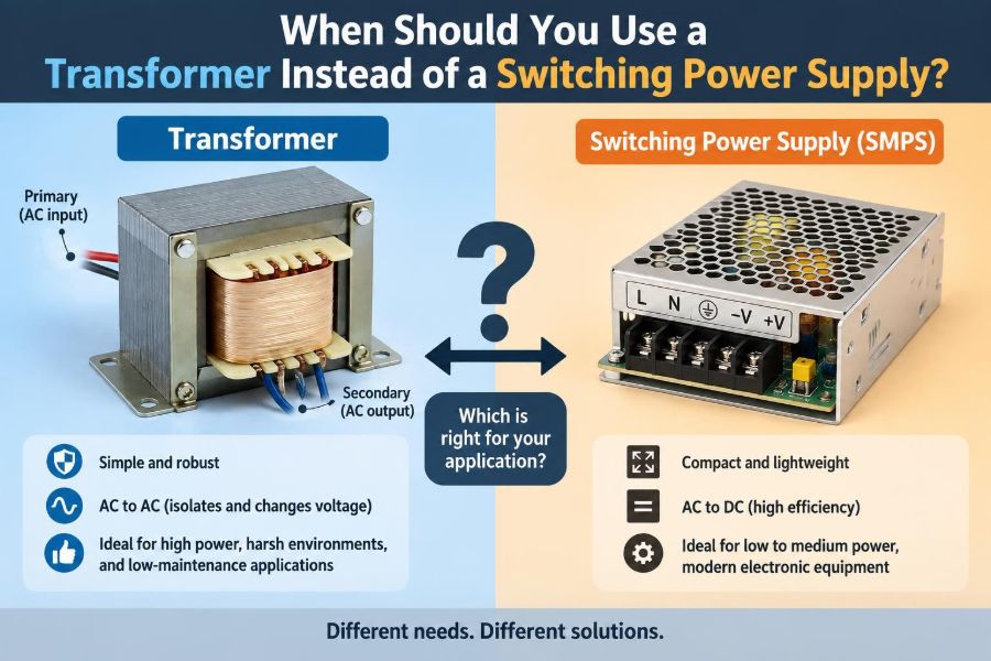
A transformer transfers energy between windings through a changing magnetic field. It changes voltage and can provide galvanic isolation, but it does not by itself convert AC to DC or regulate an output voltage.
A switching power supply, often called an SMPS, uses semiconductor switches operating at high frequency to control power flow. It can accept AC or DC, produce one or more regulated DC outputs, and may use a high-frequency transformer for isolation.
So the practical comparison is often between a line-frequency transformer power supply and a switching power supply. The first commonly uses a 50 or 60 Hz transformer, rectifier, capacitors, and perhaps a linear regulator. The second switches energy at much higher frequency and regulates it electronically.
🔌 Recognize What a Transformer Actually Needs
A conventional transformer requires alternating voltage. The changing current in its primary winding creates changing magnetic flux, which induces voltage in the secondary winding.
If steady DC is applied to an ordinary transformer primary, there is no continuing induced secondary voltage. Worse, the core can saturate, primary current can rise sharply, and the winding or upstream protection can be damaged.
That simple fact makes a transformer the natural option when the source is AC and the load genuinely needs isolated AC. It is not a direct replacement for a DC-DC converter in battery-powered equipment.
🧭 Identify Whether the Load Needs AC or DC
This is the first decision point. Many electronic circuits require DC, but many industrial and electromechanical devices are designed specifically for AC.
Examples include certain HVAC control transformers, doorbell circuits, older lighting controls, some valve actuators, and contactor coils rated for 24 V AC. Feeding one of these devices from a DC switching supply may cause incorrect operation, overheating, or a failure to pull in or release as intended.
Use a transformer when the required output is AC. Use a DC power supply when the load specification calls for DC. Never infer the requirement from voltage alone: “24 V” is incomplete without AC or DC, current, frequency where relevant, and tolerance.
🔄 Choose a Transformer for a Simple Isolated AC Source
A step-down transformer is hard to beat when the job is simply to produce a lower isolated AC voltage from mains. A 230 V to 24 V transformer or a 120 V to 12 V transformer can serve this role with few parts and straightforward behavior.
There is no high-frequency switching stage, no control firmware, and no output regulation loop to stabilize. For basic AC distribution inside a machine, that simplicity can be valuable.
Protection is still necessary. Select proper fusing, insulation class, earthing arrangement, enclosure, and transformer rating. “Simple” does not mean safe to wire casually around mains voltage.
🏭 Favor Transformers in Traditional Control Circuits
Industrial control systems often use a dedicated control transformer to supply low-voltage AC for relays, pilot lights, solenoids, and contactors. The secondary may be grounded in a deliberate way, depending on the system design and applicable requirements.
One reason is compatibility: the components may already be rated for 24 V AC or 120 V AC. Another is fault behavior. A transformer with an appropriately protected secondary can supply a robust control circuit without requiring every downstream device to accommodate electronic DC power conversion.
Modern DC control architectures are also common and often efficient. But when replacing only the source in an existing AC control circuit, retaining the transformer is frequently the correct engineering choice.
🛡️ Use Isolation as a Design Function, Not a Buzzword
Galvanic isolation means there is no direct conductive path between input and output. Both a conventional transformer supply and an isolated SMPS can provide it, but the required isolation level, construction, and approvals matter more than the word “isolated” on a listing.
A transformer is useful when you need a floating secondary for measurement, signaling, control, or safe extra-low-voltage distribution. It can also reduce the consequences of a direct connection between low-voltage circuitry and the mains supply.
Isolation does not eliminate all hazards. Capacitance between windings can couple high-frequency noise, and unsafe wiring or an inadequately rated transformer can defeat the intended protection.
🎛️ Pick Low Switching Noise for Sensitive Analog Work
High-frequency switching supplies can introduce ripple, common-mode noise, and electromagnetic interference. Good designs manage these effects well, but the design burden is real.
A transformer followed by rectification, reservoir capacitors, and linear regulation can be attractive for low-noise analog preamplifiers, laboratory front ends, audio circuits, and certain sensor interfaces. The mains-frequency magnetic field from the transformer must still be controlled through placement and orientation.
The advantage is not that linear supplies are magically noise-free. It is that their noise spectrum and failure modes can be easier to understand and filter in some sensitive applications.
🎵 Consider Audio Requirements Beyond the Voltage Label
Audio equipment is a classic case where the answer depends on implementation. A poorly filtered SMPS may create audible whine, broadband noise, or ground-related interference. A poorly placed mains transformer may induce 50 or 60 Hz hum into nearby high-gain circuits.
For a modest analog amplifier, a transformer-based supply with carefully designed rectification, filtering, grounding, and regulation can be an excellent choice. For compact powered speakers, digital mixers, and modern amplifiers, a quality SMPS may be equally appropriate or better because of its low mass and regulated rails.
Choose based on noise targets, physical layout, load transients, and grounding strategy—not on the assumption that either topology always sounds better.
📏 Understand Why Size and Weight Usually Favor Switching
At 50 or 60 Hz, a transformer needs substantial core material and copper to transfer significant power without saturating or overheating. This is why a mains transformer becomes bulky and heavy as power rises.
An SMPS switches at much higher frequencies, allowing its magnetic components to be much smaller for a similar power level. This is a major reason phone chargers, laptop adapters, and compact LED drivers use switching conversion.
If portability, shallow enclosure depth, or shipping weight is central to the product, a conventional transformer is usually at a disadvantage. That does not make it unusable; it means the mechanical cost must be accepted deliberately.
🌡️ Compare Efficiency Across the Whole System
A transformer has copper losses and core losses. If it feeds a linear regulator from a voltage well above the required DC output, the regulator dissipates the excess voltage as heat. That combination can be inefficient, especially at higher current.
Switching supplies often achieve better efficiency because they control energy transfer rather than continuously dropping large voltage differences. Less wasted power usually means less heat and smaller cooling requirements.
At low power or intermittent duty, the system-level difference may be less decisive than expected. Evaluate real load current, idle consumption, input range, and thermal conditions rather than relying on a general efficiency claim.
📉 Accept Regulation Limits When the Load Allows It
A basic transformer secondary is not tightly regulated. Its rated voltage is generally specified at a particular load, and the no-load voltage can be noticeably higher. Voltage also changes with input mains variation and winding resistance.
That is acceptable for loads such as incandescent lamps, some AC coils, simple rectifier-capacitor circuits with adequate voltage ratings, and circuits designed with tolerance in mind.
If a microprocessor, radio module, precision sensor, or battery charger requires a stable rail, a regulated SMPS or a transformer supply with suitable regulation is normally necessary. Do not treat the transformer nameplate voltage as a guaranteed DC output.
🔋 Build DC from a Transformer Only When It Makes Sense
A transformer-based DC supply follows a familiar path: AC input enters the transformer, a rectifier converts it to pulsating DC, capacitors reduce ripple, and a regulator may establish the final voltage.
The approximate peak after a bridge rectifier is related to the transformer secondary RMS voltage, but diode drops, load sag, ripple, mains tolerance, and transformer regulation all affect the real result. Design margins are essential.
This approach is practical when the power is moderate, low noise is valued, and enclosure space is available. It becomes less appealing when output power, input-voltage range, or efficiency requirements grow.
🧮 Account for Rectifier Ripple and Capacitor Stress
After full-wave rectification, reservoir capacitors charge near voltage peaks and discharge into the load between peaks. The resulting ripple rises with load current and falls with larger capacitance and higher ripple frequency.
Large capacitors are not a free solution. They increase inrush current, occupy space, age over time, and can impose high peak currents on the transformer and bridge rectifier.
When using a transformer supply, verify capacitor voltage rating, ripple-current capability, rectifier surge rating, transformer heating, and the regulator’s minimum dropout requirement at the lowest expected input voltage.
⚙️ Use a Switching Supply for Wide Input Ranges
Mains systems vary by region and installation, and some equipment must accept a wide AC input range. A properly designed universal-input SMPS can often operate across common nominal mains ranges without a manual selector.
A conventional transformer is usually wound for a specific primary voltage or for selectable taps. Operating it on the wrong mains voltage can produce an output that is too low, too high, or thermally unsafe.
For globally deployed equipment, switching conversion often reduces inventory complexity. The actual supply must still be rated and approved for the target voltage, frequency, pollution environment, and installation category.
🔋 Use DC-DC Switching Conversion from Batteries
Battery systems provide DC, so a conventional mains transformer cannot directly step that voltage up or down. A switching converter—buck, boost, buck-boost, flyback, or another topology—is the normal solution.
For example, a 12 V battery feeding regulated 5 V electronics calls for a buck converter. A battery-powered device requiring a higher voltage may need a boost or isolated flyback converter.
An inverter can first make AC and then feed a transformer, but that is usually an unnecessary path unless the system specifically needs AC distribution, waveform isolation, or compatibility with legacy AC equipment.
🏥 Examine Reliability in the Actual Environment
Neither approach is universally more reliable. A conventional transformer is mechanically simple and can have a long service life, but electrolytic capacitors, rectifiers, switches, and linear regulators around it can still fail.
An SMPS contains more active circuitry and may be sensitive to heat, surges, contamination, and component quality. On the other hand, a well-designed industrial SMPS can offer regulated output, diagnostic features, and protection functions that a basic transformer supply lacks.
Reliability comes from correct rating, thermal margin, component selection, protection design, and installation conditions. Topology alone is not a lifetime prediction.
🔥 Check Thermal Behavior at Continuous Load
Transformers run warm in normal service because winding resistance and core losses generate heat. Their temperature rise depends on load, ventilation, ambient temperature, mounting, and waveform quality.
Switching supplies may be efficient but can concentrate heat in semiconductors, inductors, and capacitors. Small sealed adapters can be particularly sensitive to blocked airflow or elevated ambient temperature.
For either option, avoid sizing exactly at the expected continuous load. Review derating guidance and test the equipment under realistic duty cycle, ambient conditions, and input extremes.
⚠️ Treat Inrush Current as a Real Constraint
A transformer can draw a high magnetizing inrush current when energized, especially if switching occurs near an unfavorable point on the AC waveform. Large reservoir capacitors add another inrush mechanism.
SMPS units also have input capacitors and can produce substantial inrush, particularly when many supplies are energized together. Circuit breakers, relays, fuses, and upstream contacts must withstand the combined effect.
For cabinets with multiple loads, consider sequencing, inrush limiting, appropriately selected protective devices, and the manufacturer’s stated inrush characteristics rather than assuming low steady-state wattage means easy startup.
📡 Plan for Electromagnetic Compatibility
Switching edges create high-frequency energy that can conduct back into power wiring or radiate from cables and enclosure openings. Filters, shielding, grounding, layout, cable routing, and controlled switching transitions all influence electromagnetic compatibility, or EMC.
Line-frequency transformers do not create the same switching spectrum, but they can produce low-frequency magnetic fields. Sensitive magnetic sensors, phono preamplifiers, and unshielded high-impedance wiring may pick up hum if placed too close.
Choose the supply that gives your complete system the clearer EMC path. In some designs that is a screened SMPS; in others, it is a remotely located toroidal transformer with carefully routed secondary wiring.
🧲 Know the Difference Between EI and Toroidal Transformers
Traditional laminated EI-core transformers are robust, widely available, and often tolerate DC offset and harsh conditions reasonably well. Toroidal transformers can be more compact and may have lower external magnetic field for a given design, but they can have high inrush current and require careful mounting.
Neither shape is automatically superior. Core type affects leakage field, regulation, cost, noise, mounting, and behavior under abnormal conditions.
Select from verified specifications: temperature class, insulation system, primary and secondary ratings, short-circuit protection method, and expected installation environment.
🧰 Value Repairability and Troubleshooting
A transformer supply is often easier to inspect with basic instruments. A technician can separately test secondary AC voltage, bridge rectifier behavior, capacitor condition, and regulator operation.
SMPS troubleshooting is more specialized. Rectified mains capacitors retain hazardous energy, high-frequency waveforms can mislead ordinary meters, and control-loop faults may require an isolation transformer, differential probing, or manufacturer documentation.
For educational equipment, low-volume machinery, or installations maintained in remote locations, straightforward serviceability can favor a transformer-based design. Safety procedures remain non-negotiable in both cases.
💰 Compare Total Cost Rather Than Unit Price
A transformer may have an attractive part cost in a simple low-power design, but the finished supply also needs a rectifier, capacitors, protection, enclosure space, and sometimes a regulator and heat sink.
An off-the-shelf SMPS may cost more or less depending on power level and certification needs, yet it can reduce assembly labor, enclosure volume, and thermal hardware. It may also provide short-circuit, overload, and overvoltage protection in one module.
Include manufacturing, wiring, testing, field replacement, shipping, losses during operation, and compliance work in the comparison. The lowest-priced component is rarely the entire cost story.
📜 Do Not Assume Compliance Transfers Automatically
Equipment connected to mains must meet applicable electrical safety and EMC requirements for its intended market and use. A transformer or power module carrying suitable approvals can help, but the finished product still needs correct integration.
Clearances, creepage distances, earthing, fusing, enclosure flammability, cable strain relief, accessible energy hazards, and thermal performance all affect the final system. A certified component installed incorrectly does not make the assembly compliant.
For professional products, involve qualified compliance and safety personnel early. For personal projects, use appropriately rated enclosed supplies and avoid exposed mains wiring unless you have the necessary competence and test capability.
🧪 Match Protection Features to the Failure You Expect
Many SMPS units include current limiting, hiccup-mode restart, overtemperature protection, and overvoltage protection. These can make them convenient for electronics that may experience short circuits or variable loads.
A transformer is inherently current-limited to some degree by winding impedance, but it can still deliver damaging fault current. Fuses, thermal cutouts, circuit breakers, and correctly rated secondary wiring remain necessary.
Ask what happens if the output is shorted, overloaded, disconnected, or connected backward. The answer should be based on the actual supply data sheet and protection coordination, not assumptions about the technology.
🔧 Avoid the “Same Voltage Means Compatible” Mistake
A 12 V AC transformer is not automatically interchangeable with a 12 V DC adapter. A device marked 12 V DC may be damaged by the higher peak voltage and reverse-polarity uncertainty of a transformer-plus-rectifier arrangement.
Similarly, an AC-rated relay coil may not behave correctly on 24 V DC because its impedance and magnetic circuit are designed around AC operation. DC coils and AC coils are distinct components even when their voltage markings look similar.
- Verify AC versus DC.
- Verify nominal voltage and permitted tolerance.
- Verify continuous, peak, and startup current.
- Verify polarity, connector type, grounding, and isolation requirements.
🧱 Use Transformer Supplies Where Rugged Simplicity Wins
A transformer-based supply is often a strong choice when the application has a fixed local mains voltage, modest power demand, generous space, and a load that needs AC or tolerates an unregulated rectified supply.
Typical candidates include legacy control circuits, educational bench projects, low-noise analog assemblies, and equipment where accessible repair is more valuable than compactness. A conservative transformer design can tolerate certain electrical abuse gracefully, provided it is correctly fused and thermally rated.
It is less attractive when energy efficiency, universal input, low weight, or tightly regulated output are leading requirements.
🚀 Use Switching Supplies Where Performance Density Wins
An SMPS is usually the practical default for compact consumer electronics, computing equipment, telecom hardware, battery-powered products, high-power DC rails, and products sold across multiple mains regions.
Its strengths are regulated outputs, high power density, efficient conversion, and flexible topology. An isolated flyback supply, for example, can create a regulated low-voltage output from mains in a much smaller package than an equivalent 50 or 60 Hz transformer supply.
These benefits require competent EMC, safety, thermal, and layout design. For a purchased module, they require selecting a reputable unit with ratings that fit the real installation.
📝 Apply a Practical Selection Checklist
Before choosing, write the requirements in electrical terms rather than starting with a preferred component. This often makes the answer obvious.
- What is the input: fixed AC mains, wide-range AC, or DC battery?
- Does the load require AC, DC, isolation, or multiple output rails?
- How tightly must output voltage be regulated?
- What are continuous load, startup surge, and fault conditions?
- How much space, weight, heat, and audible noise can the product accept?
- What noise limits apply to the load and the surrounding environment?
- What safety, EMC, serviceability, and lifecycle requirements apply?
A transformer is a sound answer when these requirements point to isolated AC, low-noise simplicity, or rugged maintainability. A switching supply is a sound answer when they point to compact, efficient, regulated conversion.
✅ The Core Principle: Choose the Function, Not the Fashion
The best choice is not determined by whether a technology is newer. A line-frequency transformer remains the right tool for many fixed-input, isolated AC, low-noise, and serviceable designs.
A switching power supply is generally better when you need efficient regulated DC, small size, low weight, wide input capability, or battery-based conversion. It may still contain a transformer; the difference is that it operates at high frequency within an actively controlled system.
Choose a transformer when its AC output, isolation, simplicity, and noise characteristics solve the actual problem; choose a switching supply when regulation, efficiency, size, and input flexibility are the real constraints.
The voltage printed on a label is only the start—match the source, waveform, regulation, load behavior, safety needs, and environment before selecting the power architecture. ⚡🔌🛠️