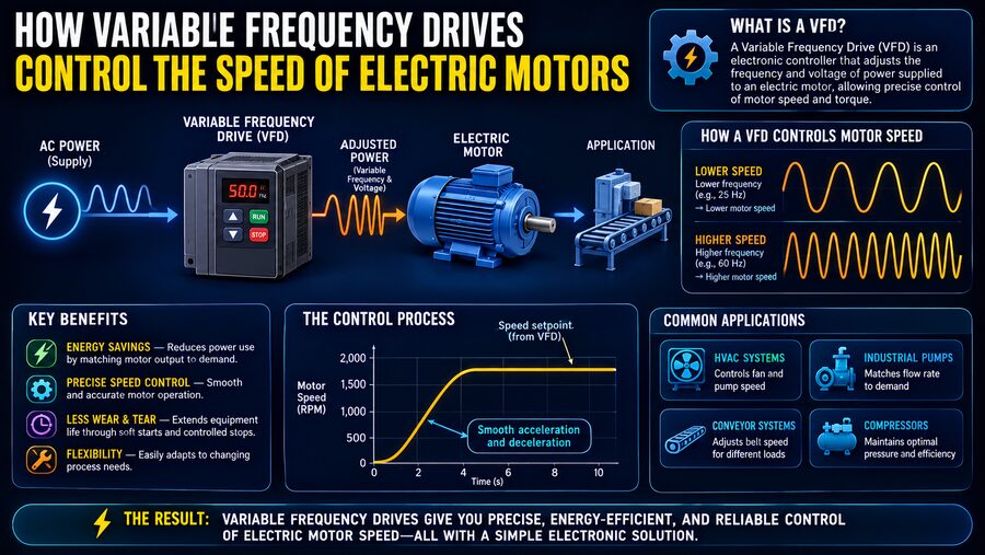

Electric motors power an enormous share of modern machinery. They run pumps in water systems, fans in ventilation equipment, conveyors in factories, compressors in refrigeration plants, elevators, machine tools, and countless other industrial processes. 🏭⚙️
But many of these machines do not need to run at full speed all the time.
A ventilation fan may need less airflow at night. A pump may need to deliver different amounts of water throughout the day. A conveyor may need to slow down for one product and speed up for another.
One of the most effective ways to control these motors is with a Variable Frequency Drive, commonly abbreviated as VFD.
A VFD controls the speed and torque of an AC electric motor by changing the frequency and voltage of the electrical power supplied to it.
The basic idea is:
Fixed-frequency AC power ➡️ VFD ➡️ adjustable-frequency power ➡️ adjustable motor speed
Instead of wasting energy by mechanically restricting a machine that is running at full speed, a VFD allows the motor itself to operate closer to the speed actually required. This improves process control, reduces mechanical stress, and can produce major energy savings. ⚡📉
🔄 Why Motor Speed Depends on Frequency
To understand how a VFD works, it helps to understand the relationship between electrical frequency and motor speed.
Many industrial AC motors are induction motors.
Inside an induction motor, alternating current flows through windings in the stationary part of the motor, called the stator.
The alternating currents produce a rotating magnetic field.
The speed of this rotating field is called the synchronous speed.
It is related to supply frequency by:
Ns = 120f / P
where:
- Ns = synchronous speed in revolutions per minute
- f = electrical frequency in hertz
- P = number of motor poles
For example, a four-pole motor supplied at 50 Hz has a synchronous speed of:
Ns = (120 × 50) / 4 = 1500 rpm
At 60 Hz:
Ns = (120 × 60) / 4 = 1800 rpm
So if the electrical frequency changes, the speed of the rotating magnetic field changes as well. 🔄
That gives the VFD its primary method of controlling motor speed.
🧲 Why an Induction Motor Runs Slightly Below Synchronous Speed
An induction motor’s rotor usually does not rotate at exactly the same speed as the stator’s magnetic field.
It runs slightly slower.
This difference is called slip.
Slip is necessary because relative motion between the rotating magnetic field and the rotor induces electrical currents in the rotor. Those currents produce the electromagnetic torque that turns the shaft.
A four-pole motor with a synchronous speed of 1500 rpm might therefore operate near 1450 rpm under load.
The exact value depends on motor design and mechanical load.
When a VFD reduces the supplied frequency, both synchronous speed and actual rotor speed decrease.
🔌 Standard Power Is Normally Fixed-Frequency
Utility electrical systems normally provide AC power at a fixed frequency, commonly 50 Hz or 60 Hz depending on the region.
If an ordinary induction motor is connected directly to this supply, its normal operating speed is largely determined by that frequency and the motor’s number of poles.
Traditionally, changing machine output might require:
- Mechanical gearboxes
- Dampers
- Throttling valves
- Belt systems
- Multiple-speed motors
These methods can work, but many are inefficient or inflexible.
A VFD creates an electronically adjustable power supply so that motor speed can be changed continuously over a broad range. 🎛️
⚙️ The Three Main Stages Inside a VFD
Although modern VFDs use sophisticated electronics, their basic power-conversion process can be understood in three stages:
1. Rectifier
2. DC link
3. Inverter
The energy path is:
AC input ➡️ DC conversion ➡️ DC storage/filtering ➡️ variable-frequency AC output
Let’s examine each stage.
1️⃣ The Rectifier Converts AC to DC
The first stage is the rectifier.
The incoming supply may be three-phase AC, for example:
400 V, 50 Hz AC
The rectifier uses semiconductor devices such as diodes or controlled switching devices to convert this alternating voltage into direct current.
The result is not necessarily perfectly smooth DC yet, but the current now flows through an intermediate DC system.
Conceptually:
AC ➡️ rectifier ➡️ DC
This may seem surprising because the motor ultimately needs AC again.
Why convert AC to DC only to turn it back into AC?
Because the intermediate DC stage gives the VFD freedom to construct a new AC waveform at almost any desired frequency. 🧠
2️⃣ The DC Link Stores and Smooths Energy
The next section is called the DC link, DC bus, or DC intermediate circuit.
It typically contains components such as:
- Capacitors
- Inductors
- Filtering circuits
Capacitors smooth the rectified voltage and store electrical energy.
The DC link therefore provides a relatively stable energy source for the inverter.
A simplified flow is:
Utility AC ➡️ rectifier ➡️ stable DC bus ➡️ inverter
Large VFDs may contain substantial capacitors because they must handle significant electrical power.
3️⃣ The Inverter Creates New AC Power
The inverter is where the VFD performs its most important control function.
Power semiconductor switches—commonly devices such as IGBTs, or Insulated-Gate Bipolar Transistors—turn the DC bus voltage on and off extremely rapidly.
By controlling exactly when these switches operate, the VFD synthesizes a three-phase output that behaves like adjustable-frequency AC power.
For example, the drive might produce an effective output frequency of:
10 Hz
25 Hz
40 Hz
50 Hz
or another value depending on the requested motor speed.
Higher output frequency generally produces higher motor speed.
Lower frequency produces lower motor speed. ⚡
📊 Pulse Width Modulation Creates the Output Waveform
Most modern VFDs use a technique called Pulse Width Modulation, or PWM.
Rather than creating a perfectly smooth sine wave directly, the inverter generates a rapid series of voltage pulses.
The width and timing of those pulses are carefully controlled.
The motor’s inductance causes the resulting current to behave much more smoothly than the individual voltage pulses might suggest.
By changing the pulse pattern, the drive can create a current waveform whose fundamental component approximates a sine wave of the desired frequency and voltage.
Conceptually:
DC voltage ➡️ high-speed switching ➡️ PWM pulses ➡️ motor current resembling AC sine wave
This switching may occur thousands of times per second. 🔲⚡
🎛️ Speed Command Determines Output Frequency
The VFD needs to know how fast the motor should run.
The command may come from:
- A knob or keypad
- A programmable logic controller
- A pressure sensor
- A flow controller
- A building-management system
- An industrial network
- An automated process controller
Suppose an operator requests 50% speed.
The VFD might respond by reducing the output frequency from 50 Hz to roughly 25 Hz, depending on the application and control strategy.
The motor then settles near the corresponding lower speed.
This makes precise automation possible.
⚖️ Why Voltage Must Change Along With Frequency
Changing frequency alone is not always sufficient.
The voltage supplied to the motor also needs to be controlled.
The magnetic flux in a conventional induction motor depends strongly on the ratio between voltage and frequency.
A simplified control approach therefore keeps:
Voltage / Frequency ≈ constant
This is known as V/f control or volts-per-hertz control.
For example, suppose a motor is rated:
400 V at 50 Hz
The ratio is:
400 / 50 = 8 volts per hertz
At 25 Hz, a simple V/f drive might supply roughly:
25 × 8 = 200 V
This helps maintain approximately the correct magnetic flux.
If full voltage were applied at very low frequency, excessive current and magnetic saturation could occur.
If voltage were too low for the selected frequency, the motor might produce insufficient torque.
🧠 Scalar Control Versus Vector Control
Simple V/f control works well for many applications such as pumps and fans.
But some machines need more precise torque and speed control.
Advanced VFDs use vector control, also called field-oriented control in many implementations.
Vector control mathematically separates the motor current into components associated with:
- Magnetic flux
- Torque production
The drive continuously calculates how the motor is behaving and adjusts its output.
This can provide:
🎯 More precise speed regulation
💪 Strong torque at low speed
⚡ Faster dynamic response
🔄 Better control during changing loads
Vector-controlled drives are commonly used for demanding conveyors, hoists, machine tools, and other applications requiring accurate motor behavior.
🔍 Sensorless Vector Control
Some advanced drives can estimate motor speed and position without using a physical speed sensor.
This is known as sensorless vector control.
The drive analyzes motor voltage and current to estimate internal motor conditions.
This reduces hardware complexity while providing better performance than basic V/f control.
For even greater accuracy, a motor may use an encoder or resolver that provides direct shaft-position or speed feedback.
🚀 VFDs Provide Smooth Acceleration
A motor connected directly to the electrical supply can start very abruptly.
At startup, it may draw a large inrush current, often several times its normal operating current.
The sudden torque can also stress:
- Belts
- Couplings
- Gearboxes
- Pumps
- Conveyors
- Shafts
A VFD can instead increase frequency and voltage gradually.
For example:
0 Hz ➡️ 5 Hz ➡️ 10 Hz ➡️ 20 Hz ➡️ 30 Hz ➡️ 50 Hz
The motor accelerates smoothly.
This process is called a ramp.
The acceleration time may be configured by the engineer.
A machine might reach full speed in 5 seconds, 30 seconds, or even several minutes depending on the application.
🛑 VFDs Also Control Deceleration
The same principle applies when stopping.
Instead of abruptly disconnecting power, the VFD can gradually lower the output frequency.
This produces controlled deceleration.
However, slowing a large rotating machine can return energy from the motor toward the drive.
In that situation, the motor temporarily behaves like a generator.
The VFD must manage this energy.
Possible strategies include:
- Longer deceleration time
- Braking resistor
- Regenerative drive
- Mechanical braking system
The correct choice depends on machine inertia and how rapidly the equipment must stop.
🔥 What Is a Braking Resistor?
During rapid deceleration, regenerated electrical energy can increase the voltage on the VFD’s DC bus.
A braking resistor converts excess electrical energy into heat.
The energy path becomes:
Rotating machine ➡️ motor generating ➡️ VFD DC bus ➡️ braking resistor ➡️ heat
This allows faster stopping than simply waiting for friction to slow the machine.
Braking resistors are often used with:
- Hoists
- Centrifuges
- Elevators
- Conveyors
- High-inertia fans
♻️ Regenerative Drives Can Return Energy
More advanced drives can return regenerated power to the electrical supply instead of wasting it as heat.
These are often called regenerative drives or active-front-end drives.
For an elevator lowering a heavy load, for example, the motor may generate electricity.
A regenerative VFD can send some of this energy back into the facility’s power system.
This can improve efficiency in machines that frequently accelerate and decelerate. ♻️⚡
💧 Why VFDs Save So Much Energy in Pumps and Fans
One of the largest benefits of VFDs appears in centrifugal pumps and fans.
Traditionally, a pump might run at full speed while a valve is partially closed to reduce flow.
This is similar to pressing a car’s accelerator while controlling speed with the brake.
The motor still consumes substantial energy.
A VFD can reduce pump speed instead.
For many centrifugal loads, the affinity laws provide useful approximations:
Flow ∝ Speed
Pressure or head ∝ Speed²
Power ∝ Speed³
The cubic relationship is especially important.
If speed is reduced to 80%:
Power ≈ 0.8³ = 0.512
So, under idealized conditions, the machine may need only about 51% of the original power.
Real systems have additional losses and constraints, but the potential savings can still be substantial. 📉⚡
🌬️ Example: HVAC Fan Control
Consider a large building ventilation fan.
At full occupancy, the fan may need to run near full speed.
During quieter periods, the required airflow may fall.
Without a VFD:
Motor runs full speed ➡️ damper restricts airflow
With a VFD:
Controller detects lower airflow demand ➡️ VFD reduces motor speed ➡️ energy use decreases
This is why VFDs are widely used in modern HVAC systems. 🏢🌬️
💧 Example: Water Pressure Control
Imagine a municipal booster pump supplying a neighborhood.
Water demand changes throughout the day.
A pressure sensor measures the pipeline pressure.
The control system compares the measurement with a target:
Target: 4 bar
If demand increases and pressure drops:
VFD increases pump speed
If demand decreases and pressure rises:
VFD reduces pump speed
The system automatically maintains nearly constant pressure while using only the pumping power required. 🚰
🏭 Common Industrial Applications
Variable frequency drives are used throughout industry.
Typical applications include:
💧 Pumps
🌬️ Fans
📦 Conveyors
🧊 Refrigeration compressors
🏗️ Cranes and hoists
🚪 Elevators
🪚 Machine tools
🏭 Process equipment
🌀 Centrifuges
⚙️ Mixers
Any machine using an AC motor whose optimum speed changes during operation may be a candidate for VFD control.
🔁 Reversing Motor Direction
A three-phase motor changes direction when the phase sequence is reversed.
A VFD can perform this electronically.
Instead of physically swapping power cables, the inverter changes the sequence of its output switching.
This allows software-controlled forward and reverse operation.
For example:
Forward ➡️ stop ➡️ reverse
can be programmed directly into the drive.
This is valuable in conveyors, winding systems, and machine tools.
🛡️ VFDs Also Protect Motors
Modern VFDs do much more than adjust speed.
They typically contain protective functions such as:
- Overcurrent detection
- Overvoltage protection
- Undervoltage protection
- Motor overload protection
- Overtemperature monitoring
- Ground-fault detection
- Stall detection
The VFD continuously measures electrical conditions and can stop the motor if unsafe operation is detected.
Some drives also support motor-temperature sensors for additional protection.
🌡️ Low-Speed Operation Can Create Cooling Problems
A standard motor often has a cooling fan mounted directly on its shaft.
At full speed, the fan moves plenty of air.
At low speed, it moves much less.
That creates an important limitation.
A motor operating slowly while producing high torque may generate significant heat but receive inadequate cooling.
Solutions can include:
- Limiting continuous low-speed torque
- Using a separately powered cooling fan
- Selecting a motor specifically rated for inverter duty
Engineers must therefore consider thermal performance, not just electrical speed control. 🌡️
⚡ Harmonics on the Power System
The rectifier inside a conventional VFD does not draw perfectly sinusoidal current from the electrical supply.
This can create harmonics.
Harmonics are frequency components at multiples of the fundamental power-system frequency.
Excessive harmonics can contribute to:
- Additional transformer heating
- Cable losses
- Distortion
- Power-quality problems
Large installations may therefore use:
- Line reactors
- Passive harmonic filters
- Multi-pulse rectifiers
- Active-front-end drives
Power-quality analysis becomes increasingly important when many large VFDs operate in the same facility.
📡 Electromagnetic Interference
The rapid switching used for PWM generates high-frequency electrical signals.
These can create electromagnetic interference, or EMI.
Poor installation practices can affect:
- Sensors
- Communication networks
- Instrumentation
- Nearby electronics
Engineers reduce interference through:
- Shielded motor cables
- Proper grounding
- Correct cable routing
- Filters
- Separation of power and signal wiring
Installation quality is therefore critical for reliable VFD operation. 📡
🧵 Long Motor Cables Can Cause Voltage Stress
PWM pulses have very fast voltage edges.
When the cable between a VFD and motor is long, wave-reflection effects can cause voltage peaks at the motor terminals.
These peaks can stress motor insulation.
For long cable runs, engineers may use devices such as:
- dV/dt filters
- Sine-wave filters
- Appropriate inverter-duty motors
The required protection depends on drive voltage, cable length, motor insulation, and switching characteristics.
🧮 How a VFD Maintains Process Control Automatically
A VFD is often part of a closed-loop control system.
Consider a tank whose pressure must remain constant.
A sensor measures actual pressure.
A controller calculates:
Error = desired pressure – measured pressure
The control system then commands the VFD.
If pressure is too low:
Increase frequency ➡️ motor speeds up ➡️ pump delivers more flow
If pressure is too high:
Decrease frequency ➡️ motor slows ➡️ flow decreases
Many VFDs include built-in PID controllers, allowing simple processes to be regulated without a separate control computer.
🖥️ VFDs Can Communicate With Automation Systems
Modern drives frequently connect to industrial networks.
They can communicate information such as:
- Current speed
- Motor current
- Output frequency
- Power consumption
- Fault status
- Temperature
- Operating hours
Commands can also be sent remotely.
A PLC may tell the VFD:
Run at 42 Hz
The VFD can respond:
Motor current = 31 A
Drive status = Running
This connectivity makes VFDs important components of modern automated factories. 🏭💻
⚖️ VFD Versus Soft Starter
A VFD is sometimes confused with a soft starter.
Both can reduce the harsh electrical and mechanical effects of motor starting, but they serve different purposes.
A soft starter primarily controls voltage during startup and often bypasses itself after the motor reaches full speed.
A VFD controls both voltage and frequency and can continuously regulate motor speed during normal operation.
In simple terms:
Soft starter: smooth startup
VFD: smooth startup + continuous speed control
If a motor always operates at full speed after starting, a soft starter may be sufficient.
If speed needs to vary, a VFD is generally the more appropriate technology.
📏 Constant-Torque and Variable-Torque Loads
Different machines place different demands on a motor.
💪 Constant-Torque Loads
These require roughly similar torque across a range of speeds.
Examples can include:
- Conveyors
- Mixers
- Positive-displacement pumps
The drive and motor must provide substantial current even at lower speeds.
🌬️ Variable-Torque Loads
Fans and centrifugal pumps typically require much less torque at lower speeds.
This is why they can provide especially large energy savings with VFD control.
Correctly identifying the load type helps engineers size and configure the drive.
🚀 Operating Above Base Frequency
A VFD can sometimes drive a motor above its rated base frequency.
For example, a 50 Hz motor might be operated above 50 Hz if the motor and mechanical system are suitable.
However, voltage cannot usually continue increasing indefinitely.
Once rated voltage is reached, increasing frequency reduces the volts-per-hertz ratio.
The motor enters a region commonly called field weakening.
In this region:
Speed may increase
but
available torque generally decreases
Engineers must verify motor, bearing, rotor, and driven-machine speed limits before overspeed operation.
🏁 How the Entire VFD Process Works
The complete process can be summarized as:
1. Fixed-frequency AC enters the VFD. 🔌
2. The rectifier converts AC into DC.
3. The DC link smooths and stores electrical energy.
4. The inverter rapidly switches the DC voltage using PWM.
5. The VFD creates a controlled three-phase output.
6. Output frequency determines the rotating magnetic-field speed.
7. Output voltage is adjusted to maintain appropriate motor flux.
8. The motor accelerates or slows to the requested speed.
9. Sensors or automation systems can continuously modify the command.
What seems like simple motor-speed control is actually a sophisticated process of real-time power conversion.
🌍 Why VFDs Matter So Much
Electric motors account for a large share of industrial electricity consumption.
Many historically operated at constant full speed even when the process did not require full output.
Variable frequency drives changed that.
Instead of wasting energy through throttling, mechanical restriction, or repeated start-stop cycling, engineers can match motor speed directly to process demand.
This can provide:
⚡ Lower energy consumption
📉 Reduced operating cost
🔧 Less mechanical wear
🚀 Smooth acceleration
🎯 Better process control
🔊 Lower noise at reduced speed
🛡️ Built-in motor protection
🌱 Reduced environmental impact
The benefits become especially significant when large pumps and fans operate for thousands of hours each year.
🏁 Conclusion
A Variable Frequency Drive controls an AC motor by changing the frequency and voltage of the electrical power supplied to it. ⚡⚙️
The drive first converts fixed-frequency AC power into DC.
It then stores and smooths that energy in a DC link.
Finally, high-speed semiconductor switches use pulse width modulation to create a new three-phase AC output whose effective frequency and voltage can be precisely controlled.
Because the speed of an AC motor’s rotating magnetic field depends on electrical frequency:
Lower frequency ➡️ lower motor speed
Higher frequency ➡️ higher motor speed
More advanced VFDs add vector control, torque regulation, regenerative braking, networking, automatic process control, and extensive motor protection.
Their real value, however, is straightforward: they allow machines to operate at the speed actually required rather than continuously running at maximum speed.
A pump can slow when demand decreases.
A fan can accelerate when airflow is needed.
A conveyor can match production speed.
An elevator can accelerate and decelerate smoothly.
By turning fixed electrical power into precisely controlled motor motion, VFDs have become one of the most important technologies in modern automation and energy-efficient industry. 🏭⚡🌱