
A conveyor begins moving as a warehouse opens for the day. A chilled-water pump starts beneath an office tower. An elevator accelerates smoothly from floor to floor. Most people notice these machines only when they stop working, yet each depends on a decision made many times every second: how much electrical power should the motor receive?
For much of industrial history, that decision was simple. A motor was either connected to the supply or disconnected from it. The equipment started abruptly, ran at essentially one speed, and stopped when power was removed.
That arrangement remains useful in many applications. But loads, energy costs, automation requirements, and reliability expectations have changed. Motor control has evolved from levers and electromechanical contacts into software-configured systems that can shape torque, speed, acceleration, protection, and diagnostic information.
Understanding that evolution helps students connect circuit theory to real equipment and helps practitioners choose controls that fit the machine rather than simply selecting the newest technology.
⚙️ Motors Need More Than a Power Connection
An electric motor converts electrical energy into mechanical motion. In a practical installation, however, the motor is part of a larger system: a pump, fan, compressor, mixer, hoist, conveyor, or machine tool. The control system must make the motor behave appropriately for that load.
Motor control commonly addresses starting, stopping, reversing, speed regulation, torque production, overload protection, and fault response. A basic switch can perform only a small part of this job. A modern drive can address many of these functions, but it also introduces design considerations of its own.
🔌 The Challenge of Starting an Induction Motor
The three-phase induction motor became a dominant industrial workhorse because it is robust, economical, and requires little routine attention. At standstill, though, its rotor has no speed-induced counteracting effect, so it can draw a current several times greater than its normal running current when connected directly to the line.
This inrush current is brief, but it can create voltage dips, mechanical shock, and stress on conductors, contactors, and the driven machine. The starting method must therefore be judged not only by whether the motor turns, but by whether the electrical supply and mechanical process tolerate its startup behavior.
🕹️ Manual Starters and the Earliest Control Panels
Early motor control often used manually operated knife switches or drum controllers. An operator physically moved a handle to make or break circuit connections, sometimes stepping through resistor positions as a motor accelerated.
These devices gave direct control but depended heavily on operator attention and exposed energized components more openly than modern enclosed equipment. They were practical in their era, particularly for straightforward machinery, yet they offered limited automatic protection and little ability to coordinate multiple devices.
🧲 Contactors Made Remote Control Practical
The electromagnetic contactor changed the architecture of motor control. A small control voltage energizes a coil, which magnetically closes power contacts capable of carrying motor current. A pushbutton, float switch, thermostat, or relay can therefore command a much larger load without carrying its full current.
This separation between control circuit and power circuit made remote operation, interlocking, and automation far easier. It also made it possible to place operators at safe stations while locating power equipment near the motor or distribution system.
🛡️ Overload Relays Added a Necessary Layer of Protection
A fuse or circuit breaker protects conductors and equipment against short circuits and severe faults. It does not necessarily protect a motor from sustained overload, such as a jammed conveyor or overloaded pump.
An overload relay monitors motor current or thermal effect and opens the control circuit when excessive heating is likely. The contactor then drops out and disconnects the motor. Proper overload selection depends on motor nameplate data, service conditions, and the applicable electrical code or standard; it should not be treated as a generic “set it high enough not to trip” adjustment.
▶️ Across-the-Line Starters: Simple and Still Relevant
An across-the-line, or direct-on-line, starter applies full line voltage to the motor immediately. It typically combines a contactor, overload protection, a disconnecting means, and start/stop controls.
The result is high starting torque and rapid acceleration, which can be desirable for a machine that must reach speed quickly. It is often suitable for small motors, stiff electrical systems, and loads that can tolerate abrupt starts. Its limitations appear when inrush current is disruptive or when mechanical acceleration must be gentler.
🔁 Reversing Starters Changed Direction Safely
Reversing a three-phase induction motor is conceptually simple: interchange any two supply phases. In a control panel, this is commonly achieved with two contactors wired in opposite phase sequence.
The safety challenge is preventing both contactors from closing together, which would create a phase-to-phase fault. Electrical interlocks and mechanical interlocks are used so that one direction must be open before the other can energize. A well-designed sequence also accounts for the time needed for a load to slow or stop before reversal.
⭐ Star-Delta Starting Reduced Line Current
For motors designed with suitable winding terminals and ratings, a star-delta starter begins the motor with windings connected in star and later reconnects them in delta for normal operation. The initial phase voltage is lower, reducing starting current drawn from the supply.
The trade-off is equally important: available starting torque is reduced significantly. Star-delta starting can work for lightly loaded equipment that accelerates readily, but it may fail on a high-inertia or high-breakaway-torque load. The transition between connections can also produce a disturbance if timing and load behavior are not considered.
🧱 Autotransformer and Resistor Starting Filled Other Niches
Autotransformer starters reduce the voltage applied to the motor during acceleration and then transfer it to full voltage. They can provide more flexible voltage taps than star-delta methods, although they are comparatively bulky and involve additional switching equipment.
Older wound-rotor induction motor systems could insert resistance into the rotor circuit to improve starting torque characteristics. These approaches illustrate a recurring engineering lesson: lowering voltage can reduce current, but the torque consequences must always be evaluated alongside it.
🌊 Soft Starters Controlled the Ramp, Not the Speed
A soft starter uses power electronic devices, commonly thyristors, to gradually increase the effective voltage delivered to an AC motor during starting. Instead of an abrupt full-voltage connection, the motor can accelerate along a configured voltage or current-limited ramp.
This reduces mechanical shock in applications such as pumps, where a sudden start can contribute to pressure transients, and conveyors, where product movement may need to be controlled. Most soft starters then apply full line voltage during normal running, often through an internal or external bypass contactor.
⚖️ Soft Starting Has Clear Boundaries
A soft starter reduces the harshness of starting, but it does not normally provide continuous speed control. Once the motor reaches full voltage, its speed remains close to the speed set by supply frequency and motor slip.
It is a strong choice when the process needs controlled acceleration and stopping but operates at one normal speed. It is not the right substitute for a variable-frequency drive when airflow, flow rate, web tension, or production rate must vary during operation.
🌀 Frequency Is the Key to Induction-Motor Speed
The synchronous speed of an AC machine depends principally on supply frequency and the number of magnetic poles. It can be expressed as nₛ = 120f / P, where nₛ is synchronous speed in revolutions per minute, f is frequency in hertz, and P is the number of poles.
An induction motor runs slightly below synchronous speed under load; the difference is called slip. Changing voltage alone has limited useful speed-control range. Changing frequency directly changes the rotating magnetic field speed, which is why variable-frequency control transformed AC motor applications.
🔧 The Variable-Frequency Drive Architecture
A variable-frequency drive, often called a VFD or adjustable-speed drive, first rectifies incoming AC into DC. A DC link smooths and stores energy, and an inverter switches that DC rapidly to synthesize an AC output with the requested frequency and voltage.
The motor does not see a smooth utility sine wave at the drive terminals. It sees a pulse-width-modulated waveform whose average effect produces the desired fundamental voltage and frequency. This switching capability gives the drive remarkable control, while also creating electromagnetic and insulation-related considerations.
📈 Volts-per-Hertz Control Preserves Magnetic Flux
At moderate operating conditions, an induction motor needs its applied voltage to change approximately in proportion to frequency. This is known as V/Hz control. If frequency is reduced without reducing voltage appropriately, excessive magnetic flux can saturate the motor core and raise current.
If voltage is too low for the chosen frequency, the motor may not develop adequate torque. Basic VFDs use this relationship to provide reliable speed control for many pumps, fans, and conveyors. Low-speed operation may need voltage boost or more advanced control because stator resistance becomes more influential.
🎯 Vector Control Improves Torque Precision
Vector control, also called field-oriented control, estimates or measures motor magnetic conditions and separates torque-producing current from flux-producing current. This is analogous to independently managing two components of a force rather than adjusting one combined quantity.
It provides stronger low-speed torque control, quicker response to changing loads, and better regulation than simple scalar V/Hz control in demanding applications. Hoists, extruders, positioning equipment, and heavily loaded conveyors may benefit. The added capability requires correct motor data, careful commissioning, and an application that actually needs it.
📡 Sensors, Sensorless Control, and Feedback
Many VFD applications operate successfully without a shaft-mounted speed sensor. The drive estimates speed from current, voltage, and a motor model; this is generally called sensorless control. It avoids extra hardware and is adequate for many process loads.
Where accurate speed at very low speed, precise positioning, or controlled torque near zero speed is required, an encoder or resolver may be added. Feedback improves information available to the controller, but it also adds wiring, setup, environmental protection, and possible failure points.
💨 Why Fans and Pumps Often Save Energy
For centrifugal fans and pumps, the affinity relationships show why speed control can be valuable: flow changes roughly with speed, pressure changes roughly with the square of speed, and power changes roughly with the cube of speed. These are approximate relationships for similar operating conditions, not universal guarantees for every installed system.
Historically, many systems ran a motor at full speed and used dampers, valves, or bypass paths to restrict output. Reducing motor speed can often avoid wasting energy across those restrictions. The actual benefit depends on the pump or fan curve, the piping or duct system, required operating points, and how many hours the equipment runs at part load.
🏭 Constant-Torque and Variable-Torque Loads Differ
Load type strongly affects drive selection. A conveyor, mixer, positive-displacement pump, or hoist may require nearly constant torque across its intended speed range. A fan or centrifugal pump commonly has variable torque that falls substantially as speed decreases.
| Load characteristic | Typical examples | Control implication |
|---|---|---|
| Variable torque | Fans, centrifugal pumps | Often excellent candidates for VFD speed reduction |
| Constant torque | Conveyors, mixers, screw feeders | Drive must supply required torque at low speed |
| Constant power | Some machine-tool spindles, winders | Torque typically decreases as speed rises above a base range |
| High breakaway torque | Crushers, loaded conveyors | Starting and overload capability require close attention |
A drive sized only from motor kilowatts can be wrong. The required torque profile, acceleration time, duty cycle, overload demand, and regenerative behavior matter just as much.
⏱️ Acceleration Is an Energy and Torque Problem
Accelerating a rotating load requires torque beyond the torque needed to overcome normal friction and process resistance. High-inertia loads, such as large fans or centrifuges, may require long ramps or a drive with suitable current capability.
If a ramp is set unrealistically short, the VFD may hit its current limit and extend the acceleration anyway, or it may fault depending on settings and application conditions. A practical commissioning process starts with conservative acceleration and deceleration times, then adjusts them based on observed current, process response, and equipment limits.
🛑 Deceleration Can Return Energy to the Drive
When a motor-driven load slows down, its stored kinetic energy has to go somewhere. The motor can become a generator, feeding energy into the drive’s DC link and causing its voltage to rise.
A lightly loaded fan may coast down without issue, while a high-inertia machine or lowering hoist can create significant regenerative energy. Solutions may include a longer deceleration ramp, a braking resistor that dissipates energy as heat, a regenerative front end that returns energy to the supply, or a mechanical braking system where holding and safety demand it.
🔇 Controlled Motion Improves Mechanical Systems
The value of modern control is not limited to energy. A gradual acceleration can reduce belt slip, gear backlash shock, water hammer risk, and stress on couplings. Controlled deceleration can help maintain product spacing on conveyors or prevent a process from overshooting.
These benefits are application-specific. A too-slow start may be unacceptable for emergency equipment, and a drive cannot compensate for a worn gearbox, blocked pipe, or incorrectly selected pump. Control should complement sound mechanical design, not conceal its problems.
⚡ Harmonics and Power Quality Need Deliberate Design
A standard VFD input rectifier draws current in pulses rather than as a perfect sine wave. This can contribute to harmonic current in the electrical system. The impact depends on drive quantity and size, source impedance, transformer capacity, and other loads on the same network.
Possible mitigation methods include line reactors, DC-link chokes, passive or active harmonic filters, and lower-harmonic drive front ends. The right choice follows a system assessment, especially in facilities with sensitive equipment or utility requirements. Adding a drive without considering upstream power quality simply moves a design obligation elsewhere.
📶 Long Motor Cables Create Output-Side Risks
The fast voltage edges from PWM inverter outputs can reflect along long motor cables. At the motor terminals, reflections may create voltage peaks that stress winding insulation, particularly with older motors or long cable runs.
Output reactors, dv/dt filters, or sine-wave filters can reduce these effects. Cable type, grounding method, switching frequency, motor insulation rating, and installation geometry all matter. Manufacturer documentation and the applicable installation rules should guide the final arrangement rather than a universal cable-length rule.
🌐 Grounding and EMC Are Part of Motor Control
Electromagnetic compatibility, or EMC, concerns both emissions from equipment and its immunity to interference. A poorly installed VFD can introduce noise into nearby sensors, communications cables, or control circuits.
Good practice often includes short, low-impedance protective-earth connections, appropriate shielded motor cable where required, careful cable routing, separation of power and signal wiring, and correctly installed input filtering. Shields and grounds must be terminated as specified for the system; improvised wiring practices can create both noise and safety problems.
🧠 PLCs Turn Motor Starters into Coordinated Systems
Programmable logic controllers, or PLCs, allow motor commands to follow sequences, process conditions, permissives, alarms, and operator selections. A pump may start only after a valve proves open, or a conveyor may wait until downstream equipment is ready.
Drives can exchange status, speed references, current information, and fault codes with a PLC over hardwired signals or industrial networks. The control architecture should still define what happens if communication fails. Critical equipment should have a deliberate fallback state, not an accidental one.
🩺 Diagnostics Changed Maintenance Work
A contactor-based starter often tells a technician only that a fuse opened, an overload tripped, or a coil did not energize. Intelligent drives can report overcurrent, overvoltage, undervoltage, phase loss, thermal conditions, commanded speed, estimated load, and communication status.
These features can shorten troubleshooting, but data is useful only when interpreted in context. Repeated overcurrent may indicate a ramp issue, a mechanical jam, incorrect motor parameters, or an undersized drive. Fault history should guide inspection rather than encourage repeated resets.
🧰 Commissioning Begins With the Nameplate and Load
Before energizing a drive, verify motor nameplate voltage, rated current, base frequency, rated speed, power, connection arrangement, and insulation suitability. Enter the required parameters accurately. Incorrect motor data can reduce control performance and undermine protective functions.
Then review the driven equipment: rotation direction, safe operating speed range, lubrication requirements, cooling at low speed, resonance zones, minimum pump flow, and process interlocks. A motor can operate electrically within limits while the machine it drives operates unsafely or inefficiently.
🚫 Common Selection and Installation Mistakes
Several errors recur because a motor system spans electrical, mechanical, and process disciplines.
- Selecting a drive only by motor power instead of current, overload duty, and load torque.
- Using a VFD on a motor that cannot cool adequately at low speed without evaluating auxiliary cooling.
- Bypassing safety functions with software commands or treating a normal stop as a safety stop.
- Opening a contactor between an operating VFD and motor without confirming the drive and sequence are designed for it.
- Ignoring minimum-speed limits for pumps, lubrication systems, or airflow-dependent equipment.
- Resetting recurring faults without investigating the root cause.
None of these problems is solved by a more expensive drive alone. They require a complete view of the application.
🦺 Functional Safety Is Different From Process Control
A stop command from a PLC or keypad is intended to control a normal process. Functional safety addresses reducing risk when people may be exposed to hazards. The required safety function depends on the machine risk assessment and applicable rules.
Many modern drives provide features such as safe torque off, which prevents the motor from producing torque when correctly integrated. It does not automatically replace every need for electrical isolation, mechanical braking, guarding, or a properly engineered emergency-stop system. Safety design should be performed by competent people with the full machine context.
🔄 Existing Starters and New Drives Often Coexist
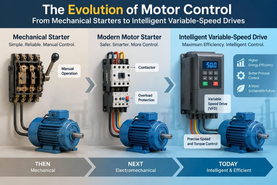
The evolution of motor control is not a sequence in which older equipment becomes useless. Across-the-line starters remain sensible for many fixed-speed loads. Soft starters remain practical where starting stress is the main concern. VFDs are justified when process variation, energy performance, controlled motion, or diagnostics create enough value.
A facility may contain all three because different loads have different needs. The engineering objective is not maximum sophistication; it is appropriate control for the electrical system, machine, process, and people who maintain it.
🧭 A Practical Method for Choosing a Control Strategy
Start by asking what the process actually needs. Is speed adjustment required during normal operation? Is the supply sensitive to starting current? Does the machine need high breakaway torque, gentle acceleration, fast reversal, or controlled braking?
- Identify the motor ratings and the mechanical load profile.
- Define start, stop, speed, torque, and safety requirements.
- Check supply capacity, fault protection, environment, and cable distances.
- Compare across-the-line, soft-start, and VFD options against those requirements.
- Plan protection, isolation, EMC, communications, and maintenance access.
- Commission with measured observations and documented settings.
This method prevents a common mistake: treating the controller as an isolated component rather than part of an engineered motor system.
🔮 Intelligent Drives Are Becoming System Participants
Modern drives increasingly act as connected devices rather than isolated speed controllers. They can share operating status with supervisory systems, adjust output from process feedback, and support condition-based maintenance strategies through trends in current, temperature, and runtime.
Connectivity brings useful visibility, but it also raises cybersecurity and configuration-management concerns. Networked drives should use deliberate access control, documented parameters, backups, and change procedures. A drive configuration is now part of the plant’s operational knowledge.
🏁 The Core Lesson of Motor-Control Evolution
Mechanical starters solved the original problem of connecting motors safely enough to useful work. Contactors and relays added remote operation and automatic protection. Reduced-voltage starters addressed electrical and mechanical stress. VFDs added the ability to shape motion continuously, while intelligent controls added communication and diagnostic insight.
The central principle has remained constant: match electrical input to mechanical need. The best design considers torque, speed, inertia, process behavior, protection, power quality, maintainability, and safety as connected decisions rather than separate checkboxes.
Motor control has evolved from simply switching power to deliberately managing motion—and the strongest solutions still begin with a clear understanding of the load and the people relying on it. ⚡⚙️🧠