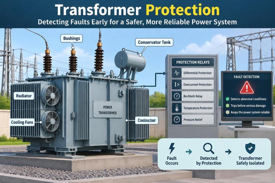

A transformer may look like a quiet piece of equipment behind a fence, inside a substation, or mounted near an industrial plant. Yet it is often carrying the electrical link between generation, transmission, and the equipment people depend on every day.
When a transformer develops a fault, the first visible sign can be deceptively small: an unusual gas alarm, a rising oil temperature, a brief current imbalance, or a change in vibration. Left unchecked, a local defect can damage insulation, deform windings, contaminate oil, and turn a repairable problem into a long outage.
Transformer protection is designed to recognize those early electrical and physical clues. It does not merely “trip when current gets high.” A well-designed scheme compares currents, watches temperatures and gases, interprets voltage behavior, and decides whether the problem is inside the transformer or elsewhere on the network.
For students, this topic connects circuit theory to real power-system decisions. For working professionals, it explains why relay settings, instrument transformers, oil tests, and maintenance records must work together rather than as isolated tasks.
🔌 Why Transformers Need Dedicated Protection
Transformers are expensive, long-lead assets with insulation systems that can deteriorate after severe electrical or thermal stress. Replacing one may require transport, installation, testing, and significant outage planning.
More importantly, many transformer faults begin internally. A protection system must therefore detect conditions that ordinary feeder overcurrent protection may not see quickly or selectively enough.
🧭 The Protection System Has Two Jobs
Every scheme balances two goals: dependability, meaning it should operate for a genuine fault, and security, meaning it should not trip for a harmless condition.
A false trip can interrupt a healthy part of the network. A missed trip can allow damage to escalate. Good transformer protection is the engineering compromise between those consequences, supported by correct design, testing, and maintenance.
⚙️ What Happens During an Internal Fault
An internal fault may be a turn-to-turn short circuit, a winding-to-ground fault, a loose connection, a core insulation failure, or a fault in a bushing or tap changer. Fault current produces intense local heating and electromagnetic forces.
In oil-filled units, an electrical arc can decompose insulating oil and paper, producing gases. A severe fault may also create pressure and move oil rapidly toward the conservator or relief path.
🧯 External Faults Can Still Stress the Transformer
An external fault occurs outside the protected transformer zone, such as a short circuit on a connected feeder or busbar. Protection should normally clear that fault using the nearest downstream breaker.
However, until it clears, the transformer can supply high through-fault current. The windings experience mechanical force roughly related to the square of current, so repeated or prolonged external faults can loosen supports and reduce future fault withstand capability.
🗺️ Protection Zones Define Responsibility
A protection zone is the physical and electrical area a relay is intended to protect. Current transformers, commonly called CTs, establish the boundaries by measuring current entering and leaving the transformer.
The main zone usually includes the transformer windings and may include leads, bushings, and associated connections depending on CT locations. Clear zone boundaries prevent gaps in protection and avoid unwanted overlap.
➗ Differential Protection Compares Current
Transformer differential protection is the principal fast protection for internal phase faults. It compares the currents measured at each side after compensating for transformer ratio and winding connection.
Under normal loading, and even for a fault beyond the zone, current entering and leaving should balance after the relay’s corrections. For an internal fault, the relay sees a significant difference, called differential or operating current, and commands a trip.
🔄 Ratio and Vector Compensation Matter
A transformer changes voltage and current magnitudes, so CT secondary currents cannot be compared directly without ratio matching. Delta and wye winding connections can also introduce a phase shift.
Modern numerical relays commonly apply these corrections in software. The underlying requirement remains the same: the relay must see balanced currents for healthy load and external-fault conditions.
🛡️ Biased Differential Logic Handles Imperfect Measurements
Real CTs are not perfectly identical. During large external faults, one CT may saturate and reproduce the primary current poorly, creating a false differential current.
Biased, or percentage-restrained, differential protection increases restraint as through current rises. In simple terms, the larger the current flowing through the transformer, the stronger the evidence required before declaring an internal fault.
🧲 Magnetizing Inrush Is Not an Internal Fault
When an unloaded transformer is energized, its core may draw a large, asymmetric magnetizing current. This inrush current can be much larger than normal load current, even though the transformer is healthy.
Because inrush enters mainly from one side, a basic differential element might interpret it as an internal fault. Protection must recognize the waveform characteristics of inrush while remaining sensitive to a real fault occurring at energization.
🎼 Harmonics Help Relays Recognize Inrush
Inrush current is often rich in harmonic content because the transformer core enters magnetic saturation. Traditionally, relays used second-harmonic restraint or blocking as one indicator that the event was inrush rather than fault current.
This method is useful but not infallible. Modern relays may combine harmonic supervision with waveform analysis, adaptive logic, and cross-phase information. Settings must reflect the transformer design and the utility’s protection philosophy.
⚡ Overexcitation Creates a Different Magnetic Problem
Overexcitation occurs when the ratio of voltage to frequency becomes too high. Since core flux is approximately related to voltage divided by frequency, a frequency reduction without an appropriate voltage reduction can push the core toward saturation.
Sustained overfluxing causes heating, noise, and elevated magnetizing current. A volts-per-hertz element, often written as V/Hz protection, detects this condition and may alarm or trip according to the expected operating limits.
🌡️ Thermal Protection Watches the Slow Damage Mechanism
Not every harmful condition is a dramatic short circuit. Insulation aging accelerates with temperature, while cooling-system failures may raise temperatures even when load current appears ordinary.
Thermal protection uses measured top-oil temperature, winding-temperature indicators, calculated thermal models, or a combination. It can start cooling stages, issue alarms, reduce loading, or trip if safe limits are exceeded.
🌀 Cooling Equipment Is Part of the Protection Story
Fans, pumps, radiators, valves, power supplies, and control circuits determine how effectively a transformer rejects heat. A failed fan bank may not immediately cause an emergency, but it reduces the allowable loading margin.
Alarm logic should distinguish a cooling alarm from a winding overtemperature trip. Operators need enough information to respond before thermal stress becomes severe, especially during high-demand periods.
🫧 Buchholz Protection Detects Gas and Oil Movement
A Buchholz relay is fitted in the pipe between the main tank and conservator of suitable oil-filled transformers. It is a mechanical device that responds to accumulated gas or sudden oil movement.
Slow gas accumulation can indicate an incipient fault, while a strong oil surge may indicate a serious internal fault. The first condition is commonly used for alarm; the second may trip. It is not applicable to every transformer construction.
🧪 Dissolved Gas Analysis Looks for Chemical Clues
Dissolved gas analysis, or DGA, examines gases dissolved in transformer oil. Different thermal and electrical fault processes can produce different gas patterns, although interpretation depends on trends, oil history, loading, and transformer design.
DGA is generally a condition-monitoring tool rather than an instantaneous protection element. A single result rarely tells the whole story; a rising trend and corroborating evidence are often more informative.
💨 Sudden Pressure Protection Responds Quickly
A rapid internal fault can produce gas faster than the tank can safely absorb the pressure rise. Sudden-pressure relays and pressure-relief devices address this hazard in different ways.
A relay may initiate tripping when it detects a rapid pressure change. A relief device mechanically vents pressure to protect the tank, but venting alone does not remove the electrical fault, so coordinated tripping remains essential.
🌍 Restricted Earth Fault Protection Finds Ground Faults
Restricted earth fault, or REF, protection is highly sensitive to faults between a winding and ground near an earthed neutral. It compares currents from the phase CTs with current measured in the neutral connection.
Its operating zone is restricted by those CT locations. REF can detect low-level internal earth faults that may not produce enough current for phase differential or overcurrent protection to operate with the desired sensitivity.
🧱 Buchings Need Their Own Attention
Bushings carry conductors through the grounded transformer tank. Their insulation can age, become contaminated, or suffer from internal deterioration, and bushing failures can be highly destructive.
Protection may detect a severe bushing fault through differential, earth-fault, or sudden-pressure operation. Condition monitoring such as capacitance and dissipation-factor trending can provide additional warning where such systems are installed.
🎚️ Tap Changers Have Separate Failure Modes
On-load tap changers regulate voltage by changing taps while energized. Their contacts, diverter switch, mechanism, and separate insulating oil can experience wear and arcing that differ from main-tank behavior.
Tap-changer oil monitoring, motor-drive alarms, operation counters, and dedicated protective devices help identify problems. Treating the tap changer as merely another part of the main transformer can hide a major maintenance risk.
⏱️ Backup Overcurrent Protection Still Has a Place
Phase overcurrent and earth-fault elements provide backup when primary protection, CT circuits, breaker trip circuits, or communications fail. They also protect against certain external faults where another device does not clear properly.
They are usually slower and less selective than differential protection. Their time-current settings must coordinate with downstream relays so that the device nearest the fault has the first opportunity to operate.
🔌 Breaker Failure Can Defeat a Correct Relay Decision
A relay can identify a fault correctly, send a trip command, and still fail to isolate it if the circuit breaker does not open. Breaker-failure protection checks whether current remains after a trip command.
If it does, the scheme may trip adjacent breakers to isolate the failed breaker and faulted transformer. This action is disruptive, but it prevents a persistent fault from remaining energized.
📡 Digital Relays Turn Measurements Into Decisions
Numerical relays sample currents, voltages, status inputs, and sometimes temperature or gas-monitor data. They apply protection algorithms, event recording, disturbance recording, logic, and communications within one device.
That integration improves visibility, but it adds responsibilities: firmware management, configuration control, access security, accurate time synchronization, and review of recorded events after abnormal operation.
🧰 Instrument Transformer Accuracy Is Foundational
Protection relays can only act on the signals they receive. Incorrect CT polarity, unsuitable CT ratio, poor saturation performance, loose secondary wiring, or an open CT circuit can compromise protection behavior.
CT circuits must never be casually opened while energized, because dangerous secondary voltages can develop. Design verification and commissioning tests should confirm polarity, ratios, grounding, and end-to-end relay operation.
📋 Settings Must Reflect the Actual Transformer
Relay settings are not transferable templates. They depend on transformer rating, impedance, vector group, tap range, grounding arrangement, CT characteristics, maximum load, source fault levels, and the surrounding network.
A setting that is highly sensitive in one installation may be insecure in another. Protection coordination studies should document assumptions, and any system modification should trigger a review.
🔍 Commissioning Proves the Scheme, Not Just the Relay
Commissioning should verify the whole chain: CT and voltage circuits, relay logic, trip outputs, breaker operation, alarm paths, lockout functions, and supervisory indications. A relay self-test cannot prove that every field wire is correct.
Useful tests include secondary injection, primary injection where practical, functional trip checks, and end-to-end testing for complex schemes. Test records provide a baseline for future troubleshooting.
🛠️ Maintenance Connects Protection With Asset Health
Protection testing alone does not reveal every developing transformer defect, and oil testing alone does not prove a relay will trip. Reliable protection comes from combining electrical tests with inspections, oil analysis, cooling checks, and operational records.
For example, a recurring high-temperature alarm may point to overloaded operation, blocked radiators, incorrect sensor behavior, or failed fans. The right response depends on evidence from several sources.
🚫 Common Mistakes That Reduce Protection Reliability
- Using generic settings: this can create blind spots or nuisance trips after a network change.
- Ignoring CT saturation: a differential scheme may misoperate on a heavy external fault if restraint is inadequate.
- Blocking too aggressively for harmonics: excessive inrush restraint can delay operation for an internal fault.
- Treating alarms as minor: gas, temperature, and cooling alarms often deserve prompt trend review.
- Skipping trip-circuit checks: detection has little value if the breaker cannot be opened.
🧩 A Hypothetical Fault Sequence
Consider a transformer with a developing turn-to-turn insulation defect. Initially, periodic oil analysis may show an unusual gas trend, while load current and terminal voltage remain normal. This is a hypothetical example, not a universal diagnostic pattern.
If the defect progresses into a significant winding fault, differential current rises sharply. Differential protection trips the transformer breakers, while sudden-pressure or Buchholz protection may also operate depending on fault energy and transformer construction. The early condition data helps investigators understand why the final trip occurred.
📚 Reading Relay Events After an Operation
After any trip, engineers should review relay targets, oscillography, sequence-of-events records, breaker status, and relevant SCADA indications. The aim is to determine whether the relay operated for an internal fault, an external fault, a wiring issue, or a setting problem.
Do not re-energize solely because a relay reset or an alarm disappeared. Return-to-service decisions should follow the organization’s procedures and consider electrical test results, transformer condition, and the suspected failure mechanism.
🧠 The Core Principle: Layered, Selective Detection
No single device can cover every transformer hazard. Differential and REF protection provide fast electrical fault detection; overcurrent supplies backup; thermal, gas, pressure, and cooling supervision reveal different forms of stress and deterioration.
The strongest arrangement is layered protection with clear zones, sound measurements, coordinated settings, and disciplined maintenance. Each layer compensates for limits in another, allowing the system to remove genuine faults quickly while avoiding unnecessary outages.
Transformer protection succeeds when it turns subtle changes in current, temperature, gas, pressure, and equipment status into a selective decision before a small defect becomes major damage. That outcome depends as much on careful engineering and maintenance as it does on the relay itself. ⚡🛡️🔧