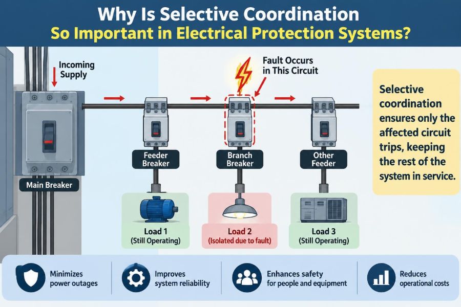

A fault occurs in a small motor circuit on the third floor of a hospital. Ideally, one nearby protective device opens, the damaged circuit is isolated, and the rest of the building keeps operating.
But if an upstream breaker trips first, the result can be much larger: an entire distribution panel, floor, or service area loses power because of a problem that began in one branch circuit.
That difference is the purpose of selective coordination. It is not simply about having circuit breakers or fuses installed. It is about arranging protective devices so the device closest to a fault acts first, while upstream devices remain closed whenever possible.
For students, this topic connects fault-current calculations, time-current curves, and equipment ratings to a practical outcome. For working professionals, it is a central question in dependable power distribution: when something goes wrong, how much of the system should have to go dark?
⚡ Selective Coordination in Plain Language
Selective coordination is the intentional matching of overcurrent protective devices so that a fault is cleared by the protective device immediately upstream of that fault, without unnecessarily opening devices closer to the source.
An overcurrent protective device is commonly a fuse or circuit breaker. It opens a circuit when current exceeds an acceptable value, whether because of overload, short circuit, or ground fault.
Think of a building electrical system as a series of gates. A problem beyond the last gate should close that last gate, not every gate back to the building entrance. Selectivity limits the interruption to the smallest practical portion of the system.
🏢 The Electrical Distribution Path
Most facilities distribute power through several levels: a service, main switchboard, feeder panels, branch panels, and final branch circuits. Each level often has its own protective device.
For example, a feeder breaker might supply a panelboard, a panelboard breaker might supply an air-handling unit, and a smaller breaker within that equipment may protect a control transformer. A fault on the transformer secondary should normally be cleared by the smallest downstream device capable of doing so.
This layered arrangement creates the possibility of coordination, but it does not guarantee it. Device ratings alone do not show which device will trip first during every fault condition.
🎯 The Core Goal: Isolate Only the Faulted Section
The primary aim is fault isolation. The affected circuit is disconnected quickly enough to protect conductors and equipment, while healthy circuits remain energized.
This matters because a fault can be local while its consequences become system-wide. A failed receptacle circuit should not remove lighting from a stairwell. A shorted fan motor should not interrupt a panel serving multiple rooms.
Perfect isolation is not always technically achievable across every possible current level. Good engineering identifies the required coordination boundaries, the credible fault scenarios, and the device combinations that provide the needed result.
🔌 Overloads and Short Circuits Behave Differently
Coordination must address more than one kind of overcurrent. An overload is current above normal operating level, often caused by excessive mechanical load, too many connected loads, or a stalled motor. It may persist for seconds or minutes.
A short circuit or low-impedance ground fault can produce much higher current almost immediately. Protective devices must react rapidly in this region to limit damage and reduce arc-flash energy.
Because devices respond differently at low and high multiples of their ratings, a pair that coordinates well for overload may fail to coordinate during a severe short circuit. Both regions need examination.
📈 Time-Current Curves Show the Coordination Story
Engineers commonly evaluate coordination with time-current characteristic curves, often called TCCs. These logarithmic plots show how long a device may take to operate at different current levels.
Current is shown horizontally, while operating time is shown vertically. A downstream device should generally operate before the upstream device for currents that can flow at the fault location.
Real devices have operating bands rather than one perfectly exact line. Manufacturing tolerances, temperature, device settings, and operating mechanisms create a range of possible response. Coordination requires considering those bands, not just nominal trip points.
⏱️ What “Downstream First” Actually Means
Suppose a 20 A branch breaker protects a receptacle circuit, and a 100 A feeder breaker supplies the panel. For a branch-circuit fault, the 20 A breaker should clear the fault before the 100 A breaker enters its own trip region.
At moderate overload current, the difference may come from inverse-time behavior: the smaller breaker responds faster. At high fault current, the challenge is greater because both breakers may use instantaneous tripping.
If both devices trip at nearly the same time, or if the feeder breaker can trip first, the system is not selectively coordinated at that fault current. The operating result may vary from event to event, which is not an acceptable design basis where continuity is critical.
💥 The Instantaneous Trip Challenge
Many molded-case circuit breakers include an instantaneous trip function. It opens the breaker with little intentional delay when current exceeds a high threshold, protecting against severe short circuits.
Instantaneous protection is valuable, but it can defeat coordination. A high downstream fault may be seen by both the branch and feeder breakers, causing the feeder breaker’s instantaneous element to operate as well.
A common misconception is that a larger breaker always trips later. At high enough current, its instantaneous element may act very quickly. Breaker frame size, ampere rating, and coordination performance are related, but they are not interchangeable concepts.
🧯 Fuses and Circuit Breakers Coordinate Differently
Fuses can provide strong selectivity because their melting and clearing characteristics can be matched in tested combinations. Current-limiting fuses also reduce the peak current and energy passed to downstream equipment during certain faults.
Circuit breakers offer resettable operation, adjustable settings in many larger frames, and integration with protective relays. Their coordination behavior depends on trip-unit characteristics, settings, and the specific devices involved.
Neither technology is automatically superior. The appropriate choice depends on maintainability, fault-current level, operational requirements, equipment limitations, and whether coordination data exist for the exact combination being considered.
🧩 Why Device Ampere Ratings Are Not Enough
It is tempting to assume that a 30 A device downstream of a 100 A device will coordinate by virtue of the ratio alone. That may be true over part of the current range, but it cannot be assumed over the full range.
Two breakers with the same ampere ratings from different product lines can have different instantaneous response ranges. A fuse and breaker with seemingly favorable ratings can also overlap in a way that produces simultaneous operation.
Use manufacturer time-current data, published selective-coordination tables, and system-specific study results. Rating ratios may be useful screening tools, but they are not a substitute for verified performance.
🗺️ Available Fault Current Changes Along the System
Available fault current is the current a power system can deliver into a fault at a given location. It is usually greatest near the source and decreases through transformers, conductors, and other impedance.
This variation matters because a breaker pair may coordinate at the far end of a long feeder, where fault current is lower, yet lose coordination close to the panel where fault current is much higher.
A proper evaluation therefore identifies fault-current values at relevant buses and loads. The question is not merely, “Will these curves separate?” It is, “Will they separate over the fault-current range that this location can actually experience?”
🔍 Minimum Fault Current Can Be Just as Important
High fault current receives much attention because it stresses equipment, but low fault current also matters. Long conductor runs, transformer impedance, and weak sources can limit fault current enough that a device operates slowly or does not enter its instantaneous range.
For ground faults in particular, current may be much lower than a bolted three-phase fault. Protection must still clear the condition within an appropriate time while avoiding unnecessary loss of upstream power.
Studies should examine credible maximum and minimum conditions, including operating configurations that change source strength. A system supplied by a utility and generator, for example, may have very different fault-current behavior in each mode.
🏥 Continuity Is a Safety Issue in Critical Facilities
Selective coordination is especially consequential where power supports life safety, emergency response, communications, process safety, or essential operations. Hospitals, data facilities, transportation infrastructure, laboratories, and industrial plants may all have circuits where broad outages create serious operational risk.
The precise rules vary by jurisdiction, facility classification, and adopted electrical code. Designers must apply the requirements that govern the project rather than treating one facility type’s rules as universal.
Even when a code does not explicitly require full selective coordination, the underlying reliability principle remains valuable: a localized electrical fault should not create an avoidable loss of unrelated critical loads.
🚨 Selectivity Also Supports Emergency Operations
Emergency generators and alternate sources are intended to preserve essential service during a normal-source outage. Their value can be reduced if a downstream fault causes an upstream emergency feeder or generator breaker to open.
Generator sources often provide lower fault current than utility sources. That can make conventional overcurrent devices slower to operate, and it can change the coordination relationships seen on a TCC.
Protection design for emergency power should therefore be evaluated in the actual source modes expected during operation, including normal, generator, and any permitted tie or parallel configurations.
🛡️ Equipment Protection and Service Continuity Must Be Balanced
Coordination is not permission to delay protection without limit. A longer upstream delay can allow a downstream device to clear a fault, but excessive delay can increase thermal stress, mechanical forces, and arc-flash incident energy.
This creates a genuine engineering tradeoff. Faster clearing can reduce damage and exposure, while intentional delay can preserve selectivity. The best arrangement is often not the one with the largest delay; it is the one that satisfies protection, coordination, equipment withstand, and safety objectives together.
Engineers may use zone-selective interlocking, differential protection, current-limiting devices, or carefully selected trip settings to improve this balance. Each approach must be analyzed as a complete protection scheme.
🔥 The Relationship With Arc-Flash Risk
Arc-flash studies estimate potential thermal energy from an arc fault under defined assumptions. Protective-device clearing time is one important input: generally, a fault that clears faster releases less energy.
Selective coordination can sometimes increase clearing time at an upstream device if time delay is used to let a downstream device act first. That may increase calculated arc-flash energy for faults in some locations.
However, poor coordination is not automatically safer. An upstream trip can de-energize broad areas and may still take longer than intended. The practical lesson is to coordinate arc-flash mitigation and selective coordination studies rather than optimizing either one in isolation.
🔗 Zone-Selective Interlocking Offers a Smarter Delay
Zone-selective interlocking, or ZSI, is a communication method used by compatible protective devices. When a downstream device detects a fault, it sends a restraining signal upstream.
The downstream device then clears the fault quickly, while upstream devices wait briefly. If an upstream device sees a fault but receives no restraint, it can trip quickly because the fault is likely within its own protected zone.
ZSI can improve both selectivity and clearing speed, but it requires compatible devices, correct wiring or communication configuration, thorough testing, and a documented failure-mode strategy. It is not simply a setting that can be assumed to work.
⚙️ Short-Time Ratings Set Practical Limits
Some low-voltage power circuit breakers are designed to withstand fault current for a specified short time while waiting for downstream protection to operate. This capability can make intentional short-time delay practical.
Not all equipment has the same withstand capability. Switchboards, panelboards, bus assemblies, breakers, and conductors must be suitable for the duty imposed by the selected protection strategy.
Coordination decisions should therefore be checked against equipment short-circuit and short-time ratings. A curve may look neatly separated on paper while the equipment cannot safely tolerate the planned delay.
📊 A Simple Hypothetical Coordination Example
Consider a hypothetical office building panel supplied by a feeder breaker. A branch breaker protects one copier circuit. A short circuit occurs in the copier’s cord or internal wiring.
If the branch breaker clears the fault, only the copier circuit is lost. If the feeder breaker trips too, the panel may also lose lighting, computers, and other receptacle circuits. If a main breaker trips, an even larger area could be affected.
| Protection outcome | Device that opens | Likely interruption scope |
|---|---|---|
| Selective operation | Branch-circuit breaker | Copier circuit only |
| Partial coordination failure | Feeder breaker | Multiple panel circuits |
| Major coordination failure | Main breaker | Large building area or service section |
This is an illustrative scenario, not a prediction for any particular equipment. Actual results depend on the available fault current and the tested characteristics of the installed devices.
🧮 Protection Studies Turn Drawings Into Decisions
A coordination study begins with an accurate one-line diagram showing sources, transformers, conductors, buses, protective devices, motors, and significant loads. The diagram is the map of the protection system.
Engineers then establish equipment ratings, conductor data, transformer impedances, source fault information, and protective-device settings. Software can calculate fault currents and plot TCCs, but reliable output depends on reliable inputs.
The study should state assumptions and operating conditions. Future readers need to know whether the conclusions apply to normal utility supply, standby generation, parallel sources, or a particular tie-breaker position.
📝 A Practical Coordination Study Workflow
- Collect current, verified field data rather than relying only on old drawings.
- Develop or update the one-line diagram and identify protection zones.
- Calculate available fault current at relevant locations for applicable source configurations.
- Plot device characteristics and compare downstream and upstream operating regions.
- Check interrupting ratings, equipment withstand ratings, conductor protection, and ground-fault behavior.
- Adjust settings or device selections, then document the final approved configuration.
- Apply settings in the field and functionally test critical schemes.
The final two steps are often underestimated. A carefully engineered setting has no protective value if a trip unit is left at a factory default or altered later without review.
🧠 Settings Matter as Much as Hardware
Electronic trip units may provide long-time, short-time, instantaneous, and ground-fault adjustments. These settings create flexibility, but they also create opportunities for mismatch.
Changing a setting to stop nuisance trips may unintentionally remove coordination, exceed a conductor’s protective limit, or increase arc-flash energy. Conversely, reducing a delay without reviewing downstream devices can cause upstream operation during faults that should stay local.
Settings should be controlled like other safety-critical configuration data: documented, labeled where appropriate, verified during commissioning, and revised through a formal process when the system changes.
🌍 Ground-Fault Protection Needs Its Own Review
Ground-fault protection senses current flowing to ground rather than returning through the intended phase conductors. In larger grounded systems, ground-fault relays or trip functions may be used to limit damage from ground faults.
Ground-fault coordination often uses intentional time delay between downstream and upstream devices. The downstream device should clear its zone first, while the upstream device provides backup if the downstream device fails.
Ground-fault protection must be designed with the system grounding method, available ground-fault current, and applicable code requirements in mind. It should not be treated as a simple add-on to phase-overcurrent coordination.
🔄 System Changes Can Undo Good Coordination
Electrical systems do not remain static. A transformer replacement, larger service, generator addition, new motor load, changed feeder length, or revised utility source can alter available fault current and device behavior.
Maintenance activities can also change settings, substitute a breaker, or replace a fuse with a different class. A device that physically fits may not preserve the original protection design.
Coordination should be reviewed after significant modifications. This is particularly important when available fault current increases, because a formerly coordinated pair may overlap in its instantaneous region under the new conditions.
🧰 Commissioning Verifies the Installed System
Design documents show intent; commissioning checks reality. Protective devices should be inspected to confirm their type, rating, sensor plugs where applicable, settings, and connection to any interlocking scheme.
For critical systems, testing may include secondary injection of trip units, functional checks of interlocks, and verification that settings match the approved study. The exact scope depends on the equipment and project requirements.
Testing should be planned carefully. Deliberately creating high-energy faults is not a normal verification method. Safer functional test methods and manufacturer procedures are used to validate protective behavior.
⚠️ Common Mistake: Designing Only for Normal Load
Load calculations answer whether conductors and equipment can carry expected current. They do not answer whether faults will be cleared selectively.
A panel can be properly sized for normal operation and still have poor fault isolation. Protection design requires another layer of analysis: fault current, device characteristics, clearing times, and backup behavior.
Do not confuse a system that runs normally with one that is resilient when abnormal conditions occur. Both are necessary design goals.
⚠️ Common Mistake: Trusting a Single Curve Snapshot
A TCC often represents one operating condition. If the model assumes utility supply only, it may not reveal how protection behaves on generator power. If it shows only maximum fault current, it may hide slow clearing at minimum current.
Likewise, a curve cannot replace checking device interrupting ratings or manufacturer-published selectivity limits. Graphical separation is useful evidence, but the required interpretation depends on device technology and data quality.
Review the full study context: source modes, fault types, settings, device tolerances, and stated limitations. A polished plot is only as sound as the model behind it.
⚠️ Common Mistake: Treating Full Selectivity as Free
Achieving coordination across a broad fault-current range can require larger devices, specific fuse classes, adjustable breakers, interlocking, or more detailed engineering. These choices may increase cost, space needs, and commissioning effort.
In some ordinary systems, partial coordination may be a reasonable outcome after risks and operational consequences are evaluated. In essential systems, the required performance may be much stricter.
The key is not to promise more selectivity than the design delivers. State the coordinated range, identify exceptions, and make decisions based on the importance of the loads affected.
🧑🔧 Maintenance Protects the Coordination Plan
Selective coordination is preserved through disciplined maintenance. Keep current one-line diagrams, protective-device setting records, study reports, and labels accessible to authorized personnel.
When a breaker trips, investigate the cause before simply resetting it or increasing a setting. Repeated trips may indicate overload, equipment failure, loose connections, or a fault condition that needs correction.
Replacement parts deserve equal care. Fuses should match the specified class and rating, and breakers should be approved for the enclosure and application. Substitution without engineering review can change protection performance substantially.
📚 What Students Should Learn to Read First
Students entering power-system protection can build confidence by learning to read one-line diagrams and TCCs before focusing on complex software. Identify source-side and load-side devices, trace fault-current paths, and ask which device owns each protection zone.
Then connect the curves to physical equipment. Learn the difference between long-time, short-time, instantaneous, and ground-fault functions, and understand why their pickup values and delays must work together.
The useful habit is to reason from a fault location outward: What current can flow? Which device should act? Which upstream device provides backup? What remains energized if the first device works correctly?
🤝 Coordination Is a Multidisciplinary Design Task
Electrical protection decisions affect architects, facility operators, safety teams, mechanical-process designers, commissioning providers, and maintenance staff. A panel outage may stop more than electrical loads; it can interrupt ventilation, controls, refrigeration, security, or production.
Early conversations about critical loads help engineers establish meaningful coordination boundaries. Facility staff can also reveal operating modes, maintenance practices, and continuity needs that are not obvious from drawings.
The strongest designs combine analytical accuracy with operational understanding. A technically correct scheme that cannot be maintained or understood by the people operating it has a reduced practical value.
✅ The Core Principle Behind Reliable Protection
Selective coordination is important because electrical protection has two jobs at once: clear dangerous fault current and preserve service to healthy parts of the system. Focusing on only one job can create a system that is either overly disruptive or inadequately protected.
A coordinated design uses verified device characteristics, realistic fault-current calculations, appropriate settings, equipment ratings, and field verification. It also recognizes limitations: coordination may differ by source mode, fault level, and device technology.
The central principle is simple: clear the fault as close to its source as possible, as quickly as necessary, and without sacrificing protection for the rest of the electrical system.
When protection is selective, a local failure is far more likely to remain local—protecting equipment, supporting safe operations, and keeping healthy loads in service. ⚡🛡️🏢