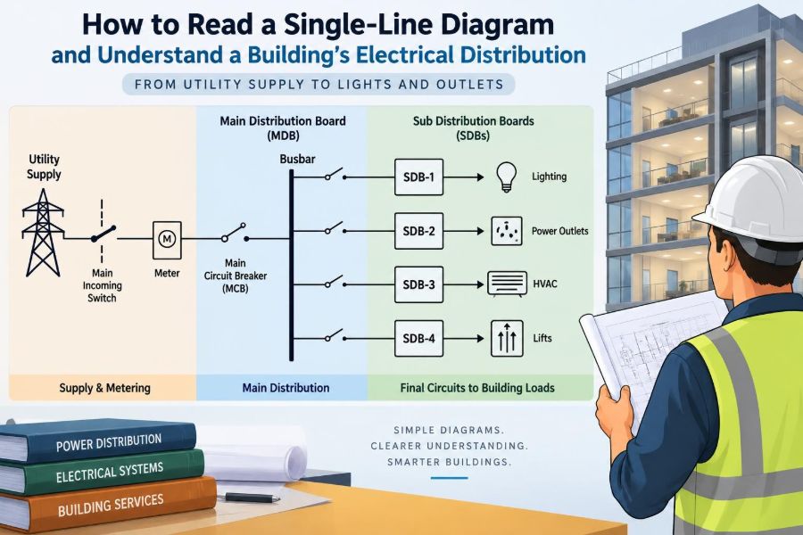

You are standing in front of an electrical room door with a maintenance request in hand. The room contains panels, transformers, switches, conduits, and warning labels—but the drawing clipped to the wall reduces all of that equipment to a handful of lines and symbols.
That drawing is usually a single-line diagram, often called an SLD or one-line. It is the map that shows how electrical power enters a building, changes voltage, passes through protective equipment, and reaches major loads.
For designers, electricians, facility teams, and students, learning to read an SLD turns an intimidating electrical system into a traceable path. You can ask useful questions: Where does this panel get its power? What breaker protects this feeder? Which equipment loses power if this transformer is isolated?
An SLD is not a substitute for safe work procedures, current field verification, or a qualified person’s judgment. But when it is accurate and read carefully, it is one of the fastest ways to understand a building’s electrical distribution.
🗺️ What a Single-Line Diagram Represents
A single-line diagram is a simplified representation of a power distribution system. One line can stand for an entire three-phase circuit rather than showing every conductor, terminal, and physical routing detail.
Its purpose is functional clarity. The drawing emphasizes source, path, voltage, protection, and load: where power begins, what equipment it passes through, and what it eventually serves.
Think of it like a transit map. It does not show the exact shape of every street, but it shows the stations, connections, and direction needed to understand the network.
🔍 Why the “Single” Line Is Enough
Many commercial and industrial buildings use three-phase AC power. A complete wiring drawing may show phase conductors, neutral conductors, equipment grounding conductors, control wiring, and terminal numbers. That detail is essential for installation, but it can obscure the overall system.
An SLD uses one line to represent the grouped phase conductors. Notes and labels identify whether the system is, for example, 480/277 V or 208/120 V, three-phase, four-wire.
This convention does not mean the circuit has only one physical conductor. It means the diagram is focused on the system-level relationship rather than conductor-by-conductor construction.
🏢 Start with the Building Service
Most SLDs are easiest to read from the utility source toward the loads. Look first for the service entrance: a utility connection, service transformer, meter, service disconnect, or main switchboard near the top or left side of the page.
A typical path might read: utility medium-voltage supply, customer-owned transformer, main switchboard, distribution panel, branch panel, and equipment. The exact arrangement depends on the building type and utility service.
Do not assume every transformer shown belongs to the building. Some diagrams distinguish utility-owned equipment from customer-owned equipment with boundaries, notes, or different line styles.
➡️ Follow the Direction of Power Flow
Power flow is usually organized vertically from top to bottom or horizontally from left to right. Arrows may reinforce the direction, but many diagrams rely only on layout.
Trace one path at a time. Begin at the source, pass through the first disconnecting and protective device, continue along the feeder, then identify the next bus, panel, transformer, or load.
When a drawing has several sources—perhaps utility power, a generator, and solar equipment—follow each source separately before trying to understand their interconnections.
⚙️ Learn the Core Equipment Symbols
Symbol styles vary by designer, software package, and project conventions. The legend is therefore more reliable than memory. Still, most SLDs contain a recognizable set of equipment types.
- Switchboard or switchgear: major distribution equipment with buses and protective devices.
- Panelboard: a smaller distribution enclosure serving branch circuits or downstream loads.
- Transformer: equipment that changes voltage, commonly drawn as paired coil symbols or a labeled block.
- Circuit breaker: a device that can interrupt fault current and often provides overcurrent protection.
- Disconnect switch: a local isolating means, which may or may not provide overcurrent protection.
- Motor or other load: an endpoint identified by a standard symbol, equipment tag, or descriptive label.
Read the label beside the symbol, not just the shape. A symbol tells you the category; the nameplate-style information tells you its role and rating.
🏷️ Decode Equipment Names and Tags
Equipment tags create the vocabulary of an electrical system. A label such as “MSB-1” may mean Main Switchboard 1, “DP-2” may mean Distribution Panel 2, and “MCC-1” may mean Motor Control Center 1.
Abbreviations are not universal. One project may use “LP” for lighting panel, while another uses “LPNL.” Find the drawing legend, panel schedules, or equipment list before making assumptions.
The tag should match labels in the field. If the SLD says a feeder supplies “P-3,” but the installed panel is labeled differently, treat that discrepancy as information requiring verification—not as a harmless drafting detail.
🔢 Read Voltage Before Reading Amperage
Voltage is the first rating to check at every major transition. It tells you what equipment can be connected and reveals where transformers divide the distribution system into sections.
In North American building systems, a common arrangement is 480/277 V three-phase, four-wire distribution feeding large mechanical loads and lighting, with a transformer producing 208/120 V for receptacles and smaller equipment. Other voltages and arrangements are common, especially outside North America.
The two numbers in “480/277 V” describe line-to-line and line-to-neutral voltage, respectively. A line-to-line load such as a three-phase motor sees 480 V; a line-to-neutral lighting circuit may see 277 V.
🔺 Recognize Three-Phase and Single-Phase Loads
Three-phase power uses three energized phase conductors. It is efficient for large loads and is common at service equipment, mechanical equipment, and distribution panels.
Single-phase loads may be supplied from a single phase and neutral, or from two phases depending on the system. The SLD may identify the load as “1Ø” or “3Ø,” using the diameter-like symbol Ø to mean phase.
A three-phase panel can serve both three-phase and single-phase branch loads when its construction and system configuration allow it. The phase designation on the diagram prevents a common mistake: assuming every downstream load uses the same connection type.
🧮 Understand the Difference Between kW, kVA, and Amps
Electrical drawings use several related ratings. Amperes (A) describe current, while volts (V) describe electrical potential. Together with phase and power factor, they relate to power.
kVA, or kilovolt-amperes, is apparent power and is commonly used to rate transformers and generators. kW, or kilowatts, is real power: the portion that performs useful work or becomes heat, light, and motion.
For AC systems, kW can be lower than kVA because of power factor. An SLD may list both, particularly for generators, UPS systems, and large loads. Do not compare them as if they are automatically interchangeable.
🚌 See the Bus as the Distribution Highway
A bus is a conductor system inside switchgear, switchboards, panelboards, or other distribution equipment. On an SLD, it may appear as a heavy line or a horizontal bar from which multiple breakers or feeders branch.
Bus ratings describe how much current the equipment can carry under its intended conditions. A 1,200 A bus does not mean every connected feeder carries 1,200 A; it defines the capacity of the common distribution path.
Watch for tie breakers or bus ties between sections. They can provide operational flexibility, but their normal open or normal closed position matters greatly for power flow and fault studies.
🛡️ Separate Protection from Isolation
A breaker often performs two jobs: it protects conductors from overcurrent and provides a means to open a circuit. A disconnect switch primarily provides isolation, although fused disconnects add overcurrent protection through fuses.
This distinction matters in troubleshooting. Opening a local disconnect may isolate a motor, but the feeder upstream can remain energized. Conversely, an upstream breaker may protect several downstream circuits rather than just one device.
Never infer that a device is safe to operate solely from its symbol. Labels, equipment instructions, lockout/tagout procedures, and site rules govern actual work.
🔥 Read Breaker Ratings in Context
Breaker information may include a frame size, trip rating, pole count, and interrupting rating. The trip rating is the current level used for overcurrent protection settings or operation; the frame is the breaker family’s physical maximum rating.
The interrupting rating is especially significant. It indicates the fault current the breaker can safely interrupt under specified conditions. It must be appropriate for the available fault current at its installed location.
A 400 A breaker in a 480 V system is not automatically comparable to a 400 A breaker in a different installation. Voltage, fault duty, protective settings, and coordination all affect whether it is suitable.
📏 Interpret Feeder and Conductor Notes
Feeder callouts often include conductor count, conductor size, material, raceway size, and grounding conductor information. A note such as “3#3/0, 1#4 G in 2 in. C” has project-specific formatting, but commonly identifies three phase conductors, one grounding conductor, and a conduit size.
These notes are not merely installation details. They help you determine whether a line represents a three-wire or four-wire feeder, whether a neutral is present, and how the designer intended grounding to be provided.
Conductor sizing depends on more than load current. Ambient temperature, grouping, terminal ratings, voltage drop, installation method, and applicable code rules may all matter. Do not reverse-engineer compliance from one abbreviated note.
🌍 Find the Neutral and Grounding Arrangement
The neutral is a grounded circuit conductor in many AC systems. It carries normal return current for line-to-neutral loads and is commonly derived from a grounded transformer winding or utility source.
The equipment grounding conductor is different. Its role is to provide a low-impedance path for fault current and bond exposed conductive equipment parts, helping protective devices operate during a ground fault.
SLDs may show grounding symbols, neutral grounding resistors, bonding jumpers, or notes such as “solidly grounded.” These details are crucial because grounding method affects fault behavior, protection, and the permissible system design.
🔄 Understand Transformers as System Boundaries
A transformer transfers AC power between windings while changing voltage and providing electrical isolation between primary and secondary circuits. On an SLD, it is a major boundary: the source-side and load-side systems must each be understood on their own terms.
Look for primary and secondary voltage, kVA rating, phase configuration, and winding connection. A transformer labeled 480 V to 208/120 V changes not only voltage but often the availability of a neutral for downstream line-to-neutral loads.
The secondary grounding and bonding arrangement is not a minor annotation. It establishes how that separately derived system is referenced to ground and how faults are cleared.
🔗 Read Delta and Wye Connections
Delta and wye describe common three-phase winding or system connections. A delta connection has windings connected in a closed loop. A wye connection joins one end of each winding at a common point, which can become a neutral when grounded.
A wye secondary such as 208Y/120 V provides 208 V line-to-line and 120 V line-to-neutral. A three-wire delta system generally does not provide the same neutral-based 120 V circuits without additional equipment.
Connection symbols and labels can look small, but they answer practical questions: Can this panel serve ordinary 120 V receptacle circuits? Is a neutral conductor expected? What voltage will a line-to-line load receive?
🚪 Identify Main-Tie-Main Arrangements
Larger switchboards and switchgear lineups may have two main incoming devices with a tie breaker between bus sections. This is often called a main-tie-main arrangement.
In one operating scheme, both mains are closed and the tie is open, keeping sources or transformer secondaries separated. Under approved procedures, one source may feed both sections through a closed tie after the other main is opened.
This arrangement can support maintenance or continuity of service, but it can also change available fault current and loading. The one-line should identify normal positions; operating the lineup requires the facility’s approved switching plan.
⚡ Locate Emergency and Standby Sources
Generators, batteries, UPS units, and other alternate sources are usually drawn as separate incoming paths. The transfer equipment between normal and emergency power is a key point to locate.
An automatic transfer switch, or ATS, transfers selected loads from normal supply to generator supply when conditions call for it. A UPS may keep sensitive loads energized through short interruptions and may be paired with a generator for longer outages.
Not every generator supplies every building load. Trace the emergency branch from the generator or ATS to learn whether it feeds life safety loads, legally required standby loads, optional standby loads, or a facility-specific critical distribution system.
🔁 Do Not Confuse Transfer Switches with Paralleling Gear
A standard transfer switch generally selects one source at a time for its connected load. Depending on its design and operating transition, it may briefly interrupt the load or perform a controlled transfer.
Paralleling gear is different: it can synchronize and operate generators together, and in some designs coordinate with a utility source. This is a specialized system with protective, control, and utility-interconnection requirements.
The visual difference on an SLD may be subtle. Read notes, device labels, and operating descriptions rather than assuming that every generator connection permits sources to run in parallel.
☀️ Trace Solar and Other Distributed Energy Resources
Solar photovoltaic systems typically appear as PV arrays feeding inverters, then an AC disconnect and a connection point on the building distribution system. Battery energy storage may appear with bidirectional power-conversion equipment.
These systems can make power flow less intuitive. During normal operation, a building may draw less utility power; under certain approved operating modes, a battery may charge or discharge. Many grid-connected solar systems stop exporting when the utility is lost unless designed with suitable islanding and backup capability.
Look for the interconnection point and any dedicated switchboard, breaker, meter, or protective device. The diagram should make clear whether the source is on the line side or load side of service equipment.
📦 Understand Panelboards and Branch Circuits
A panelboard is often the point where feeder-level distribution becomes branch-circuit distribution. Its schedule, usually on another sheet, lists circuit numbers, breaker sizes, poles, load descriptions, and sometimes calculated loads.
The SLD may show only the panel name, main rating, bus rating, voltage, and feeder. That is enough to establish its place in the hierarchy, but not enough to identify every receptacle or light fixture it serves.
For example, “LP-1” may be fed from “DP-1,” which is fed from “MSB-1.” That chain is valuable when planning an outage, locating a fault, or checking whether a proposed load has a realistic supply path.
🏭 Recognize Specialized Downstream Equipment
Some loads receive power through equipment that deserves its own symbol or tag. Motor control centers distribute power to multiple motor starters; variable-frequency drives control motor speed; elevator controllers, fire pumps, and data-room power equipment may have dedicated feeders.
A motor horsepower value or equipment kW rating is not necessarily the same as feeder ampacity. Starting current, drive characteristics, duty, protection requirements, and manufacturer instructions influence design.
Where a critical load is shown, trace both its normal supply and any alternate supply. A fire pump, for example, may have a distinct arrangement that should be interpreted using the applicable project documents and requirements.
📊 Use Load Summaries Without Treating Them as Measurements
Many SLDs include calculated demand loads at switchboards, transformers, and services. These figures support design decisions by accounting for the fact that not all connected equipment operates at full rating simultaneously.
Calculated load is not the same as a real-time meter reading. A building’s actual demand changes with occupancy, weather, operating schedules, equipment condition, and future alterations.
When evaluating spare capacity, use the SLD as a starting point and confirm with current load studies, equipment ratings, and engineering review. A spare breaker position is not automatically evidence of available electrical capacity.
🧩 Connect the One-Line to Other Drawings
An SLD answers system-level questions, but it works best alongside other documents. Panel schedules identify circuits; floor plans show equipment locations; wiring diagrams show terminals and controls; specifications describe equipment performance and installation requirements.
Arc-flash labels, equipment nameplates, maintenance records, and updated field markups also matter. A construction issue drawing may not reflect years of renovations, tenant changes, or emergency modifications.
When information conflicts, do not quietly choose the drawing that seems most convenient. Record the discrepancy and follow the organization’s process for verification and document control.
🧠 Build a Repeatable Reading Method
A disciplined sequence prevents readers from jumping between labels and losing the system’s logic. Use this method for each source and major load:
- Identify the source and its voltage, phase, and grounding configuration.
- Trace the first protective and disconnecting device.
- Follow the feeder to the next bus, transformer, panel, or transfer device.
- Record equipment tags and ratings at every transition.
- Continue until you reach the load or branch-distribution endpoint.
- Then trace backward from the load to confirm its complete supply path.
Marking a printed copy can help during study, but controlled drawings should not be altered as official records unless the project’s documentation process allows it.
📝 Work Through a Simple Hypothetical Example
Imagine a small office building with a 480/277 V utility service feeding main switchboard MSB-1. MSB-1 supplies rooftop HVAC equipment directly and also feeds transformer T-1, rated 480 V primary and 208Y/120 V secondary.
T-1 feeds distribution panel DP-1. DP-1 then feeds lighting panel LP-1 and power panel PP-1. In this hypothetical system, the path to a 120 V receptacle is utility source → MSB-1 → T-1 → DP-1 → PP-1 → branch circuit.
That path explains why opening the main breaker in PP-1 affects only downstream power-panel circuits, while opening the primary-side protection for T-1 can remove power from both LP-1 and PP-1. It also explains why HVAC equipment connected directly to MSB-1 may remain energized.
🚫 Avoid Common Interpretation Mistakes
The most frequent error is treating the SLD as a precise physical layout. Equipment drawn next to each other may be on different floors or in separate electrical rooms. Line length almost never indicates cable length.
- Do not assume a breaker is closed because it is drawn in a particular symbol position.
- Do not assume a label reflects current field conditions without verification.
- Do not confuse equipment grounding with a normal current-carrying neutral.
- Do not assume all loads downstream of a panel are backed up by a generator.
- Do not infer safe work boundaries or arc-flash conditions from an SLD alone.
A good reader distinguishes what the drawing states, what can reasonably be inferred, and what must be confirmed in the field.
🦺 Keep Safety at the Center of Interpretation
Reading an SLD is an analytical activity; operating or opening electrical equipment is a safety-critical activity. A diagram can help identify likely energy sources, but it does not prove that conductors are de-energized.
Electrical work should be performed by qualified persons using applicable procedures, appropriate PPE, lockout/tagout practices, and test instruments. Stored energy, backfeed from generators or solar systems, and incorrect documentation can create hazards not obvious from a drawing.
For students, the right habit is simple: use the one-line to plan questions, then learn how qualified workers verify isolation through formal procedures.
📚 Know What the Diagram Cannot Tell You
An SLD usually cannot show every conduit route, conductor termination, control interlock, protective relay setting, or field modification. It may also omit temporary equipment and small loads that were not relevant to the original design scope.
It is therefore a model of the system, not the system itself. Its value depends on accuracy, revision control, and the reader’s ability to recognize its intended level of detail.
For protection coordination, short-circuit analysis, arc-flash assessment, or operational switching, consult the relevant engineered studies and current site documentation rather than relying on a general one-line alone.
✅ The Core Principle: Trace, Verify, and Respect the System
A single-line diagram becomes readable when you stop seeing it as a page of symbols and start seeing it as a sequence of energy decisions. Every major device either supplies power, changes it, distributes it, protects it, controls its source, or consumes it.
Start at a known source, follow the power path through labeled equipment, check voltage and phase at each transition, and identify the protective device that governs each feeder. Then confirm the drawing against schedules, labels, and field conditions.
The practical goal is not to memorize every symbol. It is to develop a reliable mental map of how power moves through the building—and to recognize where that map needs qualified verification.
Read a single-line diagram as a power path, verify it as a real installation, and never let a simplified drawing replace safe electrical practice. ⚡🏢🦺