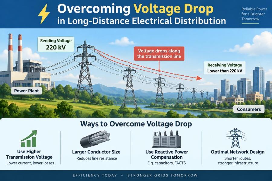

A pump at the far end of a farm starts sluggishly. A workshop’s lights dim when a compressor starts. A remote communications cabinet reports a low-voltage alarm even though the source supply measures correctly at the panel.
These are familiar field symptoms of voltage drop: the reduction in voltage that occurs as electrical energy travels through conductors, joints, protection devices, and other impedance along a circuit. On a short branch circuit, the reduction may be insignificant. Across a long feeder, it can decide whether equipment performs normally at all.
Long-distance distribution is not solved by choosing “bigger wire” alone. It requires a coordinated view of load behavior, conductor impedance, power factor, system voltage, installation conditions, protection, and future expansion.
This article develops that view from first principles, then turns it into a practical design and troubleshooting process.
🔌 What Voltage Drop Actually Means
Voltage is the electrical potential available to push current through a load. When current flows through a conductor with resistance and reactance, some source voltage is consumed along the path. The receiving equipment therefore sees less voltage than the sending end.
The difference is commonly expressed in volts or as a percentage:
Voltage-drop percentage = (sending voltage − receiving voltage) / sending voltage × 100
A 12 V circuit losing 1 V has a much larger relative problem than a 480 V circuit losing 1 V. Percentage gives the more useful comparison.
🧭 Why Long Runs Change the Design Problem
Every meter of cable adds impedance. More importantly, every meter is present in both the outgoing and return path of a single-phase or DC circuit. A 300 m load may require analysis of roughly 600 m of conductor path.
Long runs also tend to serve remote loads with difficult starting behavior: motors, pumps, welders, battery chargers, heating systems, and electronic power supplies. The steady-state load may work acceptably while a brief current surge produces an unacceptable voltage dip.
⚙️ Resistance: The Direct Source of Loss
Resistance converts electrical energy into heat. For a simplified DC or resistive AC circuit, voltage drop is:
Vdrop = I × R
Resistance increases with conductor length and decreases as conductor cross-sectional area increases. Copper and aluminum have different resistivities, so equal-sized conductors do not have equal resistance.
The associated heating loss is I²R. This is why doubling current does not merely double conductor heating; it increases it by a factor of four when resistance is unchanged.
🌀 Reactance and the AC Reality
Alternating-current conductors also have inductive reactance. Current creates a magnetic field, and that field affects the voltage relationship along the circuit. In larger AC systems, especially with long parallel conductors or cables in magnetic raceways, reactance can be material.
For balanced three-phase circuits, a commonly used engineering form is:
Vdrop ≈ √3 × I × L × (R cosφ + X sinφ)
Here, cosφ is power factor, R is resistance per unit length, X is reactance per unit length, and L must use units consistent with the impedance data. Applicable local design methods and manufacturer data should govern final calculations.
📏 The Four Variables That Dominate Drop
Most voltage-drop decisions begin with four questions: how much current flows, how far it travels, what conductor impedance is used, and what voltage the load must receive.
- Current: higher current produces greater drop.
- Length: longer circuits have more impedance.
- Conductor material and size: these determine resistance and ampacity.
- System arrangement: DC, single-phase, and three-phase circuits have different path and calculation relationships.
Installation temperature, grouping, harmonics, and power factor can add further constraints.
🔋 DC Circuits Are Especially Sensitive
Low-voltage DC systems are unforgiving because a few volts represent a large percentage of the supply. This affects solar arrays, battery systems, telecommunications equipment, control circuits, electric vehicle charging auxiliaries, and landscape lighting.
Consider a hypothetical 24 V load drawing 10 A through a long two-wire run. Even a modest resistance in each conductor can remove several volts at the load. The equipment may still be energized, but its controller, motor, or charger may operate outside its intended range.
Raising distribution voltage and converting near the load is often more practical than sending low-voltage DC over a long distance.
⚡ Single-Phase Circuits Need the Return Path
A common mistake is calculating voltage drop using only one-way distance. In a conventional two-wire single-phase circuit, current leaves on one conductor and returns on another. Both conductors contribute resistance.
This does not mean every installation can be reduced to a simple “double the distance” rule. Shared neutrals, multiwire arrangements, and non-linear loads require more careful treatment. But for a dedicated two-wire feeder, neglecting the return path can dramatically understate the drop.
🔺 Three-Phase Distribution Uses Conductors Efficiently
Balanced three-phase systems deliver power efficiently because the three phase currents are displaced in time and their vector relationship changes the voltage-drop calculation. For a given power transfer, three-phase equipment generally uses lower conductor current than a comparable single-phase arrangement at the same line voltage.
This is one reason long industrial feeders often favor three-phase distribution. It does not eliminate voltage drop, but it can make conductor size, losses, and motor performance more manageable.
🏭 Load Type Matters as Much as Load Size
A resistive heater draws relatively predictable current. A motor, transformer, welder, or switched-mode power supply may behave very differently during starting, acceleration, fault conditions, or changing load.
Motor starting deserves special attention. An induction motor can draw several times its running current while accelerating. If the feeder impedance is high, voltage at the motor terminals collapses during the start. Reduced voltage also reduces available motor torque, extending acceleration and worsening the event.
🧲 Power Factor Alters AC Voltage Drop
Power factor describes the relationship between real power and apparent power in an AC system. Inductive loads such as motors draw reactive current in addition to the current associated with useful mechanical output.
Lower power factor generally means more current for a given real-power demand, which raises resistive loss. It also changes the reactance term in an AC voltage-drop calculation. Power-factor correction can reduce upstream current in suitable installations, but it must be engineered carefully to avoid overcorrection, resonance, or poor behavior under variable loading.
🌡️ Temperature Changes Conductor Resistance
Metal conductors become more resistive as temperature rises. Cable resistance values may be published at a reference temperature, while a loaded conductor in a hot raceway or direct-buried installation operates at a higher temperature.
That distinction matters when the design has little margin. Ampacity adjustment addresses safe conductor temperature; voltage-drop assessment addresses delivered voltage. A circuit can satisfy one requirement and still be weak on the other.
🧱 Connections Can Become Hidden Bottlenecks
Long cable is visible, but poor terminations are often the real culprit. Loose lugs, corroded splices, damaged strands, undersized connectors, and incompatible materials add localized resistance.
Unlike a distributed cable drop, a bad connection creates concentrated heating. Thermal discoloration, melted insulation, intermittent operation, or a sharply hotter joint on an infrared inspection are warning signs. Connections must be installed with the specified preparation, hardware, torque, and environmental protection.
📉 Why Equipment Behaves Badly at Low Voltage
Undervoltage affects equipment differently. Incandescent lamps dim, while some electronic drivers shut down or repeatedly restart. Contactors may chatter. Battery chargers may limit output. Motors may run hotter because they draw increased current to sustain load, or they may fail to start.
Not every symptom is voltage drop; supply regulation, transformer capacity, harmonics, and equipment faults can produce similar observations. The useful test is to measure voltage at both source and load while the problematic load is operating.
🔥 Voltage Drop and Energy Loss Are Related, Not Identical
Voltage drop is a delivered-voltage problem. Conductor loss is an energy-efficiency and heating problem. They arise from the same impedance but should be evaluated separately.
A circuit may have acceptable terminal voltage at a lightly loaded device while still wasting substantial energy over long operating hours. Conversely, a short-duration motor start may cause a serious voltage dip without representing a major annual energy loss.
📐 Choosing a Design Target
Electrical rules and project specifications vary by jurisdiction, application, and governing code. Some guidance documents provide recommended voltage-drop ranges, but recommendations are not substitutes for applicable requirements or equipment instructions.
A sensible design target depends on the load. Sensitive electronics, motor starting, emergency systems, and remote controls may need tighter delivered-voltage limits than a simple heating load. Treat the target as a system-performance requirement, not a universal number.
🧮 Start With a Load Schedule
Good feeder design begins before a cable size is selected. Build a load schedule that distinguishes continuous load, normal diversified demand, future allowance, and starting or inrush current.
- List each load’s rated voltage, current, power, and phase arrangement.
- Identify motors and their starting method.
- Record duty cycle and simultaneous operation assumptions.
- Separate normal operating current from maximum credible demand.
- Document expansion loads that are reasonably expected.
Using only nameplate totals can oversize some systems; ignoring coincident operation can undersize others.
🗺️ Measure the Real Route Length
Route length is not a straight-line map distance. Include vertical risers, detours around structures, panel slack, equipment tails, and the actual trench or tray route.
For large projects, route measurement should be coordinated with civil, mechanical, and structural constraints. A late route change can add enough length to invalidate an otherwise careful voltage-drop calculation.
🧵 Increase Conductor Size Strategically
Upsizing conductors lowers resistance and voltage drop. It is often the most direct solution, particularly where the distribution voltage cannot change and the load is relatively stable.
However, larger cable costs more, is harder to pull, needs larger terminations and raceways, and may exceed equipment lug ranges. The best selection balances installed cost, losses over operating life, voltage performance, fault duty, and physical constructability.
🏗️ Raise the Distribution Voltage
For a given power level, higher voltage means lower current. Lower current sharply reduces resistive voltage drop and heating. This is the central reason utilities transmit power at high voltage and step it down near customers.
Within a facility, a transformer or suitably rated power-electronic converter near the remote load can be preferable to an enormous low-voltage conductor. The trade-off is added equipment, protection coordination, maintenance, and conversion losses.
🔄 Put Transformation Closer to the Load
A remote transformer changes the economics of distance. Rather than distribute a large current at low voltage, the system distributes a smaller current at higher voltage and supplies the final utilization voltage locally.
This approach is common for remote buildings, irrigation systems, large outdoor equipment, and industrial zones. Location must account for access, ventilation, enclosure rating, grounding, fire considerations, and local serviceability—not merely electrical distance.
🚀 Reduce Motor Starting Stress
Where voltage sag occurs primarily during motor starting, solve the starting problem rather than blindly designing every conductor for locked-rotor current. Options may include soft starters, variable-frequency drives, reduced-voltage starters, or sequencing motors so they do not start together.
These methods have limits. A soft starter reduces starting current but may not suit every load. A variable-frequency drive introduces harmonic and compatibility considerations. The motor, driven machine, feeder, and protection scheme must be assessed together.
⚖️ Balance Three-Phase Loads
In a four-wire three-phase system, unequal phase loading creates neutral current and unequal phase voltage drops. One phase can become the practical limiting condition even if total feeder loading looks reasonable.
Balance should be checked using measured demand rather than assumed load distribution. Single-phase loads added gradually over years are a common source of imbalance in workshops, commercial buildings, and mixed-use facilities.
🛡️ Protection Must Still Work
Upsizing a conductor improves voltage drop, but it does not automatically resolve protection design. Overcurrent protective devices must protect the conductor and coordinate with downstream devices. Fault current at the remote end must also be sufficient for protective devices to operate as intended.
Long conductors can reduce available fault current because their impedance limits it. This is a separate safety issue from normal voltage drop and may require a formal short-circuit and protective-device study.
🌍 Underground, Overhead, and Raceway Differences
Installation method influences both electrical and thermal behavior. Underground cable may have different heat dissipation and reactance characteristics from cable in air. Overhead conductors face weather exposure and mechanical sag. Metal raceways can affect AC conductor behavior if conductors are installed improperly.
Use impedance and ampacity data appropriate to the actual cable construction and installation method. Generic resistance values are useful for early estimates, not necessarily final construction decisions.
🔍 Field Testing: Measure Under Load
The most revealing voltage-drop test compares source and receiving-end voltage while the relevant load is operating. If possible, log voltage during startup, peak production periods, and switching events rather than relying on a single idle reading.
Useful measurements include line-to-line and line-to-neutral voltage, phase current, power factor, neutral current, and connection temperatures. Follow safe measurement practices; energized testing belongs to qualified personnel using appropriate instruments and protective procedures.
🧪 Separate Cable Drop From Supply Sag
If source voltage itself falls when a load starts, the problem may be upstream transformer impedance, generator capacity, service conductors, or source regulation. If source voltage stays stable but remote voltage falls, the feeder is more strongly implicated.
Measure at several points if practical: supply terminals, feeder origin, feeder end, and load terminals. This turns troubleshooting from guesswork into a voltage profile that identifies where the loss occurs.
🚫 Common Design Mistakes
- Using one-way length for a two-wire circuit without accounting for the return conductor.
- Calculating only full-load running current and ignoring motor starting.
- Using ampacity alone as the cable-sizing criterion.
- Assuming a new circuit will remain lightly loaded forever.
- Ignoring poor power factor, phase imbalance, or non-linear loads.
- Choosing terminals that cannot accept the upsized conductor.
- Overlooking remote-end fault-current and protection performance.
Each mistake comes from treating voltage drop as an isolated arithmetic exercise instead of a system behavior problem.
📊 A Practical Decision Sequence
Work through decisions in an order that prevents rework:
- Define acceptable voltage at the actual load terminals.
- Establish normal, maximum, and transient current conditions.
- Confirm route length, circuit configuration, and installation method.
- Calculate voltage drop with appropriate impedance data.
- Check ampacity, thermal conditions, faults, grounding, and protection.
- Compare alternatives: larger conductor, higher voltage, local transformation, or load-control changes.
- Verify the installed system with measurements under representative load.
💼 Evaluating Cost Over the System Life
Lowest first cost is not always lowest total cost. A smaller conductor may be cheaper to install but continuously dissipate more energy, run hotter, and leave little room for growth. A larger conductor can reduce losses for decades, especially on heavily loaded, continuously operated feeders.
That said, very large conductors may offer little benefit on lightly used circuits. Compare realistic load profiles, energy costs, maintenance implications, and expansion plans rather than applying one rule everywhere.
🧠 The Core Principle: Design for Delivered Performance
Voltage drop is best understood as a delivery problem. The source can be correctly sized and the cable can be safely rated, yet the system still fails if the load receives inadequate voltage during the condition that matters most.
Reliable long-distance distribution comes from managing current, distance, impedance, and load behavior as one coordinated system. Conductor upsizing is valuable, but higher-voltage distribution, local transformation, balanced loading, sound connections, and thoughtful motor control may provide a better overall answer.
When a remote load misbehaves, measure voltage where the work is being done—not only where power begins. That habit turns voltage drop from a frustrating mystery into a solvable engineering problem. ⚡🔧📏