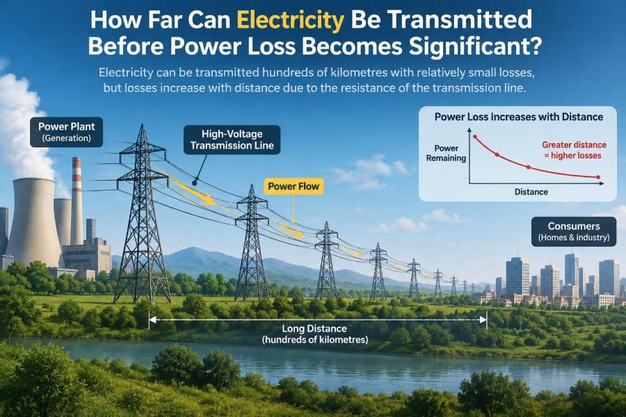

A power station may be hundreds of kilometres from the homes, factories, trains, and data centres it serves. When someone switches on a light, the journey behind that simple action is usually invisible: generators, transformers, transmission towers, substations, local distribution lines, and finally the wiring in a building.
A natural question follows: how far can the electricity travel before too much of it is lost along the way? The short answer is that there is no single distance. A well-designed high-voltage line can move large amounts of power across a continent, while a poorly sized low-voltage cable can waste substantial energy over a comparatively short run.
Distance matters, but it is only one part of the engineering problem. Voltage, current, conductor size, material, line type, power factor, weather, and the amount of power being delivered all affect the answer.
Understanding these trade-offs explains why the grid uses towering transmission lines, why neighbourhood transformers sit close to customers, and why a phone charger cable cannot simply be made kilometres long.
⚡ There Is No Universal “Maximum Distance”
Electricity is not used up merely because it travels. Instead, a transmission system loses some energy and experiences voltage changes as current flows through real conductors and equipment.
“Significant” loss is also a design judgement. A loss that may be acceptable for a long interregional connection could be unacceptable in a factory feeder, a battery-powered device, or a critical data-centre circuit. Engineers compare the cost of losses, equipment, land, reliability measures, and expected lifetime operation.
🧭 Separate the Grid Into Transmission and Distribution
The electrical grid is usually divided into transmission and distribution. Transmission moves bulk power from generators or major grid hubs over long distances at high voltage. Distribution delivers it from substations through towns and streets at lower voltage.
This separation is practical. High-voltage equipment is expensive and requires clearances, insulation, and specialist operation. It is worthwhile for bulk power, but not for the final connection to an ordinary home.
🔥 The Main Loss Mechanism: Resistive Heating
The most familiar line loss is resistive heating. Every practical conductor has electrical resistance, so moving current through it produces heat. The basic relationship is:
I²R loss = current² × resistance
If current doubles, resistive loss becomes four times larger when resistance is unchanged. This square-law relationship is why controlling current is central to long-distance power transmission.
That heat is not mysterious energy disappearance. It warms the conductor and surrounding air, then ultimately dissipates into the environment. On an overhead line, this also affects conductor temperature and sag.
🔌 Why High Voltage Changes the Distance Question
Electrical power is approximately the product of voltage and current. For a given amount of power, raising voltage allows the same power to be sent with lower current.
For example, a hypothetical 10 MW transfer at 10 kV requires far more current than the same 10 MW transfer at 100 kV. With the same line resistance, the lower-current case has dramatically lower I²R loss. This is the reason transformers are used to step voltage up before long transmission routes and down near customers.
📐 Resistance Depends on More Than Length
Longer conductors have more resistance, but length is not the only variable. Resistance depends on the conductor material, cross-sectional area, and temperature. In simplified form:
R = ρL / A
Here, ρ is material resistivity, L is length, and A is cross-sectional area. A larger conductor reduces resistance; a longer conductor increases it. As metal warms, its resistance generally rises, so actual line losses change with operating conditions.
🧵 Conductor Size Is an Economic Decision
Making a conductor thicker reduces resistance and losses, but it adds material cost, weight, structural loading, and installation difficulty. A massive cable is not automatically the best solution.
Engineers choose a size by balancing upfront capital cost against decades of energy losses and operational limits. A route carrying high power most of the time may justify a larger conductor than one used only occasionally for backup.
🪙 Why Copper and Aluminium Are Common
Copper has low resistance and is compact for a given current capability. It is common in building wiring, machinery, and many cables, where limited space can matter greatly.
Aluminium is lighter and typically used extensively in overhead transmission and distribution conductors. Its conductivity is lower than copper’s, so a larger cross-section may be needed, but its low mass helps make long spans practical. Overhead conductors may also use a reinforcing core for mechanical strength.
🌡️ Temperature, Sag, and Seasonal Ratings
A loaded overhead conductor heats from electrical losses and sunlight, then cools through wind and ambient air. Hotter conductors expand and sag farther between towers. Excessive sag can violate ground-clearance requirements.
This means a line’s practical power rating can vary with weather. Cool, windy conditions may remove heat effectively, while still, hot conditions may impose a stricter limit. The distance has not changed, but the allowable current has.
📉 Voltage Drop Is Different From Energy Loss
Voltage drop is the reduction in voltage between the sending and receiving ends. It is related to conductor impedance and current, but it is not identical to resistive energy loss.
A circuit can have a voltage-drop problem even where heat loss is modest, particularly at low voltage. Motors may draw more current or perform poorly when voltage is too low; electronic equipment may shut down or malfunction. Good design checks both quantities.
〰️ AC Lines Have Impedance, Not Just Resistance
Alternating-current lines have impedance, a combination of resistance, inductive reactance, and capacitive effects. Inductance arises because current creates a magnetic field; capacitance arises from electric fields between conductors and to ground.
At short distances and low voltages, resistance often dominates everyday calculations. At transmission voltages and long distances, reactance and capacitance strongly influence voltage control, stability, reactive power flow, and the usable line capacity.
🧲 Reactive Power Uses Line Capacity
In AC systems, some loads such as motors, transformers, and certain power-electronic equipment exchange energy with electric or magnetic fields. This is described as reactive power.
Reactive power does useful work in maintaining voltage and magnetic fields, but it still contributes to current. More current means more heating and less capacity for delivering real power, the portion that produces heat, motion, light, or computing work.
🏭 Power Factor Affects Local and Industrial Feeders
Power factor describes how effectively current is converted into real power in an AC system. A lower power factor means more current is needed to deliver the same real power at a given voltage.
For a facility with many induction motors, improving power factor with properly engineered correction equipment can reduce current in its internal network. That can reduce losses and voltage drop, though correction must be designed carefully to avoid resonance and switching problems.
🗺️ AC Transmission Has Practical Distance Limits
AC can and does travel very long distances. However, as an AC line becomes longer, managing its impedance, charging current, reactive power, and voltage becomes increasingly demanding.
Very long AC routes may require devices such as shunt reactors, capacitor banks, synchronous condensers, or flexible AC transmission system equipment. The exact economic crossover point varies greatly with route length, cable versus overhead construction, grid strength, and required capacity.
🌊 Undersea Cables Pose a Different Challenge
Submarine and underground AC cables have much higher capacitance than comparable overhead lines because their conductors are close to grounded metallic screens and insulation layers. Their capacitive charging current consumes part of the cable’s current capability.
For sufficiently long cable routes, AC charging current becomes a dominant constraint even before resistive heating alone would be limiting. This is one important reason long submarine links often use high-voltage direct current.
➡️ HVDC Is Built for Certain Long Routes
High-voltage direct current, or HVDC, transmits power as direct current. A DC line does not have AC frequency-related reactive-power flow or cable charging current in the same way, making it especially useful for long overhead corridors, long underwater cables, and connections between asynchronous AC grids.
HVDC requires costly converter stations at its ends, where power is converted between AC and DC. Those terminals can outweigh the line advantages on short routes, so HVDC is not a universal replacement for AC. It becomes attractive when distance, cable length, controllability, or grid interconnection needs justify it.
🔄 Converter Losses Must Be Counted Too
It is misleading to compare only the losses in an AC line and a DC line. An HVDC project includes conversion equipment, filters, transformers, cooling systems, and station auxiliary loads.
The relevant comparison is total delivered power and lifecycle cost for a specific project. A route may favour AC when it is shorter and must connect many intermediate substations; a point-to-point cable crossing may favour HVDC because the cable behaviour changes the equation.
🏙️ Why Electricity Reaches Cities From Distant Sources
Large generating resources are often located far from demand. Hydroelectric stations need suitable rivers and elevation. Wind and solar projects follow resource availability and land conditions. Thermal plants may be near fuel, cooling water, or industrial infrastructure.
High-voltage networks make it possible to share those resources across regions. The goal is not zero loss at any cost; it is reliable delivery with losses low enough to make the overall system worthwhile.
🏘️ Why Voltage Is Stepped Down Near Users
High voltage reduces transmission current, but it is unsuitable for ordinary consumer wiring. Insulation requirements, fault energy, equipment complexity, and public safety demands all increase with voltage.
Substations progressively reduce voltage as power moves closer to users. Local transformers then supply voltages appropriate for buildings and equipment. The final low-voltage segment is intentionally short because current is relatively high there.
🚗 A Useful Analogy: Delivering Water at Pressure
Imagine delivering a fixed amount of water through a pipe. If the pipe carries the same flow at a higher pressure, the required volume flow can be lower for the same hydraulic power. Lower flow reduces friction losses.
Voltage is not literally water pressure and current is not literally water flow, but the analogy captures the key design strategy: for a fixed power transfer, increasing voltage reduces current and therefore conductor heating.
🧮 A Simple Hypothetical Loss Calculation
Suppose a two-conductor low-voltage feeder has a total loop resistance of 1 Ω and carries 100 A. Its resistive loss is 100² × 1 = 10,000 W. That is a substantial continuous heat load.
If the same power could be transferred at ten times the voltage with one-tenth the current, and the conductor resistance stayed the same, the loss would be 10² × 1 = 100 W. Real three-phase networks and transmission lines require more complete calculations, but the current-squared lesson remains valid.
🔺 Three-Phase Power Uses Conductors Efficiently
Most utility transmission and industrial power systems use three-phase AC. Three sinusoidal voltages, offset in time, provide smooth power transfer and efficient operation of motors.
For balanced loads, three-phase systems deliver substantial power with less conductor material than an equivalent arrangement of separate single-phase circuits. Engineers use formulas involving line-to-line voltage, current, and power factor to size these systems accurately.
🌩️ Corona Loss Appears at Very High Voltage
At very high electric-field strength, air around a conductor can partially ionize, producing corona discharge. It can cause a faint glow, audible noise, radio interference, and energy loss.
Utilities reduce corona by selecting suitable conductor diameters, bundle arrangements, surface quality, and clearances. Corona is not usually the main loss mechanism on every line, but it becomes an important design consideration as voltage rises.
🌧️ Weather Can Change Both Loss and Reliability
Rain, contamination, salt spray, ice, wind, lightning, and vegetation all affect overhead-line operation. Wet or polluted insulators can develop leakage paths; ice adds mechanical load; lightning can cause transient faults.
Transmission distance therefore involves more than electrical efficiency. A route must be designed for insulation coordination, tower strength, access for maintenance, protection systems, and the local environment.
🧱 Underground Lines Trade Visibility for Thermal Limits
Underground cables avoid many visual and weather-exposure issues, but their heat is harder to remove. Soil thermal properties, burial depth, duct arrangement, nearby circuits, and seasonal ground conditions affect allowable current.
Installation and repair can also be more complex than for overhead lines. Underground construction may be the right choice in dense urban areas or sensitive corridors, but its thermal and AC-capacitance constraints must be designed into the project.
🔋 Energy Storage Does Not Eliminate Transmission Needs
Batteries and other storage can shift energy in time and support local reliability, but they do not automatically remove the value of long-distance transmission. A region may still need remote renewable output, generation diversity, or support during local outages.
Conversely, storage near demand can reduce peak loading on constrained lines. The best solution often combines transmission, local resources, demand management, and storage rather than treating them as substitutes in every situation.
🧠 Grid Stability Can Limit Transfers Before Heating Does
A line may be thermally capable of carrying more current while the wider AC system cannot safely transfer more power. Large transfers change voltage angles and reactive-power needs, and disturbances can challenge synchronism between generators.
Protection systems, contingency planning, and stability studies establish operating limits. So the answer to “how far” is sometimes constrained less by watts lost as heat than by whether the interconnected system remains stable after a fault or equipment outage.
🛡️ Reliability Requires Redundancy
A single line may be efficient, but a reliable grid cannot assume every component will always be available. Utilities plan for outages caused by maintenance, storms, faults, or equipment failures.
Parallel paths, reserve capacity, sectionalizing equipment, and automatic protection add cost, yet they reduce the consequences of a single failure. A route’s practical value is therefore measured by dependable delivered power, not only by its normal-condition losses.
🧰 Practical Design Checks for Engineers
When evaluating a feeder, cable, or transmission concept, start with the required power, voltage, route length, load profile, and installation environment. Then assess electrical performance alongside safety and constructability.
- Calculate expected current, including power factor where relevant.
- Check conductor resistance at realistic operating temperature.
- Calculate losses and receiving-end voltage under normal and peak conditions.
- Check ampacity, insulation limits, clearances, and fault-duty requirements.
- For long AC routes, model reactive power, charging current, voltage regulation, and stability.
- Compare alternatives using total project cost and expected energy loss, not a single headline metric.
⚠️ Common Misconceptions About Distance and Loss
- “Electricity cannot travel far.” It can travel very far when voltage, conductors, and grid controls are designed for the task.
- “High voltage creates extra power.” It does not. Transformers exchange voltage for current while incurring some losses.
- “All loss is just resistance.” Resistance is crucial, but long AC systems also involve reactive power, capacitance, inductance, corona, and stability limits.
- “Underground is always more efficient.” Cable resistance, thermal conditions, and AC capacitance can make the comparison route-specific.
- “A percentage loss alone tells the whole story.” The importance of loss depends on energy volume, operating hours, economics, and reliability requirements.
📏 What “Significant” Means in Practice
A few percent loss over a large bulk-power transfer represents a meaningful amount of energy and operating cost, so transmission planners work hard to reduce it. Yet eliminating every additional fraction of a percent can require disproportionate investment.
On a small low-voltage circuit, a similar percentage may show up as poor equipment performance or an overheated conductor. Context matters: the acceptable limit is set by system purpose, codes and standards, safety margins, equipment ratings, and the cost of alternatives.
🌍 Long-Distance Transmission Supports a Changing Grid
As generation becomes more geographically diverse, transmission can connect sunny, windy, hydro-rich, industrial, and urban regions. Geographic diversity can help balance changing output and demand, although it also requires coordinated planning and community engagement along routes.
New lines are not simply “wires from A to B.” They are infrastructure projects involving land use, environmental review, resilience, permitting, equipment supply, and integration with existing networks.
✅ The Core Principle: Distance Is Managed, Not Defeated
Electricity can be transmitted across very long distances with manageable losses when engineers use high voltage, adequate conductors, suitable technology, and careful control of the wider power system. The most basic rule is simple: for a fixed power transfer, lower current sharply reduces resistive heating.
But no line is judged by distance alone. AC or DC choice, overhead or underground construction, reactive-power behaviour, thermal limits, reliability, safety, and economics determine whether a particular route is sensible.
Electricity can travel remarkably far, but efficient transmission comes from managing current, voltage, and the entire network—not from distance being irrelevant. That is why the grid changes voltage several times between a generator and a wall socket. ⚡🔌🌍