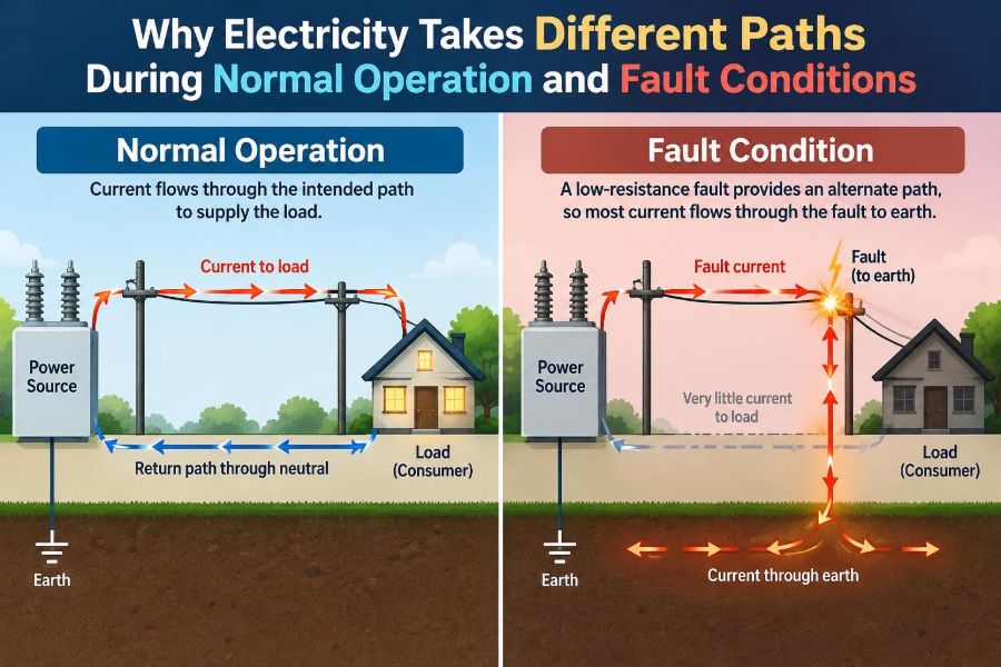

A lamp turns on, a motor starts, and a phone charger quietly does its job. In each case, current follows a planned route through conductors, switches, loads, and a return path. Most of the time, the system behaves so predictably that the wiring is easy to forget.
Then a fault occurs: insulation is damaged, a cable is crushed, moisture enters an enclosure, or a conductor touches a metal frame. Suddenly, current may take a route that was never intended to carry it.
This is often described with the shortcut “electricity takes the path of least resistance.” The phrase is memorable, but incomplete. Current does not choose one road and ignore all others; it distributes among every available path according to the electrical conditions.
Understanding that distinction explains why protective devices work, why grounding matters, why a person can be shocked, and why a fault can produce enormous current even when a normal load operates safely.
🔌 Normal operation starts with an intentional circuit
A circuit is designed as a complete loop. A source creates a voltage difference, conductors provide a route, a load converts electrical energy into light, heat, motion, or electronics, and a return conductor completes the path to the source.
For example, in a simple mains-powered lamp, current travels from the supply through the live conductor, through the lamp, and back through the neutral conductor. The lamp’s resistance limits current and turns electrical energy into useful light and heat.
Normal current is supposed to flow through a defined load. The conductor sizes, switch ratings, fuse or breaker settings, and insulation are selected around that expected route.
⚖️ Current follows all available paths
If two or more conductive paths connect the same two electrical points, current divides between them. A path with lower impedance generally carries more current, but paths with higher impedance can still carry some current.
This is why “least resistance” should not be taken literally. It is better to say that current distributes according to the impedance of each parallel path and the voltage across it.
In direct-current circuits, resistance is usually the main factor. In alternating-current systems, impedance also includes inductive and capacitive effects, which can significantly influence how fault current behaves.
📐 Ohm’s law explains the basic relationship
Ohm’s law is expressed as V = I × R, or rearranged as I = V / R. For a given voltage, lower resistance allows higher current.
Consider a hypothetical 120 V circuit. A 60 Ω heater element would draw about 2 A under simplified conditions. If a fault creates a 0.2 Ω path across the supply, the calculated current would be far larger—although the real value is limited by transformer impedance, supply conductors, connections, and other system factors.
The essential point is simple: removing the intended load resistance can cause current to rise rapidly.
🧭 Voltage creates the driving force
Voltage is an electrical potential difference. It is the condition that can drive charge through a complete conductive path, much as pressure difference can drive water through a pipe.
A conductor at one voltage is not automatically dangerous merely because it is energized. A hazardous current requires a path from that conductor to another point at a different potential, often through equipment, earth, or a person.
That is why contact conditions matter. Touching a live conductor while fully isolated is electrically different from touching it while also connected to ground or another conductor, though neither situation should ever be treated casually or tested in practice.
🛠️ Loads are useful resistance and impedance
A load is not simply an obstacle to current. It is the component intended to use electrical energy in a controlled way. A resistive heater produces heat, a lamp produces light, and a motor develops torque through magnetic fields.
Many loads have impedance that changes during operation. A motor, for instance, draws a relatively high current while starting because it has not yet developed the counter-electromotive force that limits current during normal rotation.
This is one reason protection design must distinguish between expected temporary current, such as motor starting current, and fault current caused by unintended conductive paths.
🧵 Conductors also have resistance
Wires are excellent conductors, not perfect ones. Every cable has resistance determined by its material, length, cross-sectional area, and temperature. Connections, terminals, switches, and busbars add resistance too.
During normal operation, voltage drop along conductors is usually kept within acceptable limits through proper design. During a fault, those same resistances help limit current—but often not enough to prevent dangerous heating before a protective device operates.
A long, undersized cable can create another problem: its impedance may reduce fault current enough that a breaker does not trip as quickly as intended. That is why conductor sizing and protective-device coordination belong together.
🧲 Alternating current introduces impedance
In AC systems, the opposition to current is called impedance, written as Z. It combines resistance with reactance, the frequency-dependent effect of inductors and capacitors.
Transformers, motors, cable inductance, and power-factor-correction capacitors all influence impedance. Consequently, fault-current calculations in industrial systems are more complex than dividing nominal voltage by a single resistance value.
For practical safety work, engineers use measured or calculated prospective fault current, loop impedance, equipment ratings, and time-current curves rather than relying on a simplified slogan.
💥 What makes a fault different
A fault is an unintended electrical connection or abnormal condition that disrupts the planned circuit. It may connect conductors together, connect a live conductor to exposed metalwork, or connect a conductor to earth.
The fault path often bypasses all or part of the load. Instead of current passing through a lamp filament or motor winding as intended, it can pass through copper conductors, metal enclosures, structural steel, damp surfaces, or damaged insulation.
The danger is not only that current goes somewhere unexpected. It is that the new path may have low impedance and may contain materials not designed to carry fault current.
⚡ Line-to-line faults bypass the load
A line-to-line fault occurs when two energized conductors at different voltages contact each other. In a single-phase system, this can mean live-to-neutral; in a three-phase system, it can involve two phases.
Because the fault may create a short route back toward the source, current can be very high. The exact value depends on source capacity, transformer impedance, cable lengths, and the resistance or arcing characteristics of the fault.
These faults commonly produce enough current to operate an overcurrent protective device quickly, provided the system is correctly designed and the device has adequate interrupting capacity.
🌍 Ground faults depend on the grounding arrangement
A ground fault occurs when an energized conductor contacts grounded metalwork, a protective conductor, earth, or another grounded path. Its behavior depends strongly on the type of electrical system and how neutral and protective grounding are arranged.
In many low-voltage installations, the protective conductor provides a deliberately low-impedance path back to the source. This encourages sufficient fault current to operate the fuse or circuit breaker rapidly.
Earth itself is not always a low-resistance return route. Soil resistance can be substantial and variable, so safe fault clearing cannot be assumed merely because equipment is connected to a grounding electrode.
🧱 Exposed metalwork can become energized
Equipment cases are normally non-current-carrying conductive parts. They may include a washing machine cabinet, motor frame, metal conduit, or tool housing. If a live conductor contacts that metalwork, the entire accessible surface can rise to a hazardous voltage.
Bonding and protective earthing connect those conductive parts so they remain near the same potential and provide a predictable fault-current route. This reduces the chance that a person becomes the most effective connection between energized metal and ground.
Grounding does not make a fault harmless; it helps create conditions for fast protective disconnection.
👤 A person is never a preferred safety path
The human body can conduct electricity, especially when skin is wet, damaged, or in contact with conductive surfaces. Body resistance varies widely, as do the path through the body, contact area, duration, voltage, and the current waveform.
A person may receive a shock if they bridge two points at different potentials. Examples include touching an energized enclosure while standing on a grounded floor, or contacting two conductors at once.
It is unsafe to predict injury from a single resistance value or to assume footwear, dry skin, or a low-voltage label will always provide protection. Electrical work requires established safe procedures, isolation, verification, and suitable protective measures.
🚫 A short circuit is not always a dead short
The phrase “short circuit” often suggests a zero-ohm connection. Real faults usually have some impedance: a loose contact, carbonized insulation, water contamination, an arc gap, or damaged cable strands.
A high-impedance fault may draw less current than a solid metallic short. That can make it harder for conventional overcurrent protection to detect promptly, even though local heating or accessible-voltage hazards remain possible.
This is why fault protection cannot rely on one device or one measurement alone. The fault type and system arrangement determine which protective method is effective.
🔥 Heat rises with the square of current
Resistive heating is approximately described by P = I²R. Doubling current through the same resistance produces about four times as much heating.
At a loose terminal, even modest resistance can become a serious hot spot when current is high. Under fault conditions, concentrated heating can damage insulation, melt metal, ignite nearby combustible material, or worsen the connection.
This relationship explains why protection must act quickly. A conductor may survive a brief fault current that would severely damage it if sustained.
🌩️ Arcs create a different kind of path
An arc is a discharge through ionized gas. Once formed, it can conduct current across an air gap even though ordinary air is normally an insulator.
Arc faults can arise from loose terminations, damaged cords, deteriorated insulation, or separation at a failing connection. The arc path may be unstable, intermittent, and resistive, so it may not produce enough current to trip a standard breaker immediately.
Arc-fault protective devices, where used and appropriate, look for electrical signatures associated with hazardous arcing. They complement rather than replace correct wiring, sound connections, and ordinary overcurrent protection.
🧯 Fuses respond to excessive current
A fuse contains an element designed to melt when current and heating exceed its intended limits for long enough. Once it operates, it opens the circuit and must be replaced with the correct type and rating.
Fuses are effective because they can clear high fault currents quickly when properly selected. However, replacing a blown fuse with a larger rating or improvised conductor defeats the protection and can expose wiring to destructive energy.
The fuse protects conductors and equipment under defined conditions; it does not automatically protect a person from every shock scenario.
🔘 Circuit breakers combine protection and switching
Circuit breakers commonly use thermal and magnetic mechanisms. The thermal part responds to sustained overloads, while the magnetic part can respond rapidly to large short-circuit currents.
Breaker trip curves matter. A device selected for one circuit type may nuisance-trip on expected inrush current, while another may allow too much time before operating under a low-level fault.
Breaking capacity matters too. A breaker must be able to interrupt the prospective fault current at its installation point without failing dangerously. This is a design and verification issue, not a visual judgment.
🧠 Residual-current devices watch for imbalance
A residual-current device (RCD), ground-fault circuit interrupter, or similar device compares the current leaving on active conductors with the current returning. Under normal conditions, the currents balance.
If some current returns by another path—possibly through earth or a person—the device detects the imbalance and disconnects the circuit when its operating threshold and timing conditions are met.
These devices are highly valuable additional protection, particularly where shock risk is increased. They do not eliminate the need for earthing, correct overcurrent protection, insulation integrity, or safe work practices.
🧩 Protection works as a coordinated system
Effective electrical safety comes from layers that support one another. Insulation prevents contact, enclosures prevent access, grounding and bonding manage fault paths, and protective devices disconnect abnormal circuits.
In larger installations, coordination aims to isolate the faulted section while keeping healthy parts energized. If a small branch-circuit fault trips only the branch breaker, disruption is lower than if an upstream main device opens first.
- Overload protection addresses excessive current in an otherwise intended path.
- Short-circuit protection addresses high current from unintended low-impedance paths.
- Earth-fault and residual protection addresses current escaping the normal return path.
- Arc-fault protection can address certain hazardous arcing conditions.
🏠 Household examples make the distinction visible
A toaster heating normally is a designed resistive load. Its element limits current and converts energy to heat. A damaged cord whose conductors touch each other is a fault that bypasses the element.
A refrigerator compressor also shows why normal current can vary. It may draw higher current at startup, then settle as it runs. That is expected behavior, unlike a winding-to-frame fault that energizes the casing or causes abnormal current.
Household circuits should never be diagnosed by repeated breaker resetting. A breaker that trips again may be identifying a damaged appliance, overloaded circuit, wiring defect, or moisture-related fault.
🏭 Industrial systems have more fault-current energy
Industrial sites may have large transformers, multiple sources, generators, motors, and extensive busbar systems. These can supply substantial fault current, which increases the thermal and mechanical stress on equipment.
Engineers perform short-circuit studies to determine available fault current and verify that switchgear, breakers, fuses, cables, and protective settings are suitable. Arc-flash hazard assessment may also be required because an arc can release intense thermal energy.
The same physical principle applies as in a small circuit: current follows available paths. The analysis is simply more detailed because the source, network, and consequences are larger.
📏 Fault-loop impedance affects disconnection time
Fault-loop impedance is the total impedance around a fault path back to the source. In a typical line-to-case fault, it can include the supply conductor, the fault, the protective conductor, bonding paths, transformer winding, and source connections.
Lower loop impedance generally permits higher fault current, helping an overcurrent device operate rapidly. Excessively high loop impedance can allow a metal enclosure to remain energized longer than intended during a fault.
Testing and calculation methods vary by system and jurisdiction. Qualified personnel use appropriate instruments and follow local electrical rules rather than treating a generic numerical threshold as universal.
🔩 Loose connections change the circuit over time
Electrical paths are not fixed forever. Vibration, thermal cycling, corrosion, poor termination torque, and mechanical damage can increase connection resistance over time.
A connection may initially carry normal current but gradually heat, oxidize, and become still more resistive. This feedback process can lead to overheating or intermittent arcing without a large enough current increase to trip a conventional breaker.
Inspection, correct installation torque, compatible materials, and maintenance are practical ways to prevent these failures—especially in high-current equipment and vibrating machinery.
💧 Water changes insulation and surface paths
Pure water is not an especially good conductor, but ordinary water commonly contains dissolved minerals and contaminants. Moisture can lower insulation resistance, create surface leakage paths, and accelerate corrosion.
Condensation inside enclosures can be particularly troublesome because it may be intermittent. A circuit can appear normal when dry and fault only under humid conditions, rain, washdown, or temperature changes.
Equipment must be selected and installed for its environment. Outdoor, wet, dusty, corrosive, and washdown locations need appropriate enclosures, cable entries, and inspection practices.
🧪 Measurement reveals paths that cannot be seen
A visual inspection can find crushed cables, discoloration, loose terminals, and damaged insulation, but it cannot confirm every electrical condition. Testing may include continuity checks, insulation-resistance tests, loop-impedance measurements, earth-fault testing, and thermal imaging.
Each test has limits. Insulation testing can damage sensitive electronics if applied incorrectly, and continuity alone does not prove a protective path will clear a fault adequately under operating conditions.
Testing should be planned around the equipment, its energy sources, and manufacturer guidance. For energized troubleshooting, the risks can be significant and qualified personnel should use formal safe-work controls.
🧰 Safe troubleshooting begins with isolation
When equipment behaves abnormally, the instinct to “see if it is live” can create avoidable exposure. The safer approach is to identify energy sources, isolate them, prevent reconnection where required, and verify absence of voltage with suitable test methods.
Capacitors, batteries, generators, photovoltaic systems, and back-fed circuits can remain energized even after a main supply is switched off. A single disconnecting device may not isolate every source.
- Do not bypass fuses, breakers, interlocks, or protective earth conductors.
- Do not repeatedly reset a tripping device without investigating the cause.
- Do not assume a metal enclosure is safe because it looks intact.
- Escalate faults involving burning smells, heat, damaged insulation, water ingress, or unexplained tripping.
🧱 Common myths lead to poor decisions
One myth is that electricity always goes directly to ground. In reality, it needs a complete path back to the source, and many return paths may exist. Grounding arrangements influence those paths but do not override circuit physics.
Another myth is that a breaker trips whenever someone is shocked. A person may limit current enough that an overcurrent breaker sees no abnormal load, which is why residual-current protection and other safeguards matter.
A third myth is that low resistance is always bad. Low resistance is desirable in protective bonding and intended conductor paths; it is dangerous when it forms an unintended connection between points with different voltage.
🧮 A simple parallel-path example
Imagine two parallel return paths from an energized metal case to the source: a protective conductor with very low impedance and a person standing on a conductive floor with much higher, variable impedance. Current divides between both paths.
The low-impedance protective conductor carries most of the fault current and helps the protective device operate. The person is not made safe by being a “higher resistance path”; any body current can be hazardous, and conditions can change dramatically.
This hypothetical example illustrates the engineering aim: provide a deliberately robust fault path so the fault is cleared rapidly, rather than allowing unpredictable paths through people or structures.
🗺️ Design choices shape where fault current goes
System grounding method, transformer connections, neutral bonding location, protective-conductor routing, cable size, and device settings all shape fault behavior. They should be designed as one system rather than selected independently.
For example, a protective conductor routed with its associated circuit conductors helps keep the fault loop compact and predictable. Separating it unnecessarily can increase loop impedance and introduce electromagnetic effects during faults.
Local codes and standards specify many details because acceptable arrangements depend on supply system type, voltage, location, and equipment use. Design assumptions should be documented and verified during commissioning and modifications.
📚 The core principle: intended paths versus fault paths
During normal operation, electrical current travels through intended components that limit, control, and use energy. During fault conditions, damaged insulation, unintended contact, arcing, or moisture can create additional paths that bypass the intended load.
Current divides among available paths according to voltage and impedance. Low-impedance fault paths can produce high current; high-impedance faults may produce persistent heating or shock hazards without obvious overcurrent.
The goal of electrical design is not to stop current from following physics, but to provide safe intended paths, prevent unintended ones, and disconnect faults before damage or injury occurs.
When a circuit is understood as a complete network rather than a single “chosen” route, normal operation, short circuits, grounding, protective devices, and safe troubleshooting all make much more sense. Electricity follows available paths; good engineering determines which paths are available and what happens when one fails. ⚡🛡️🔧