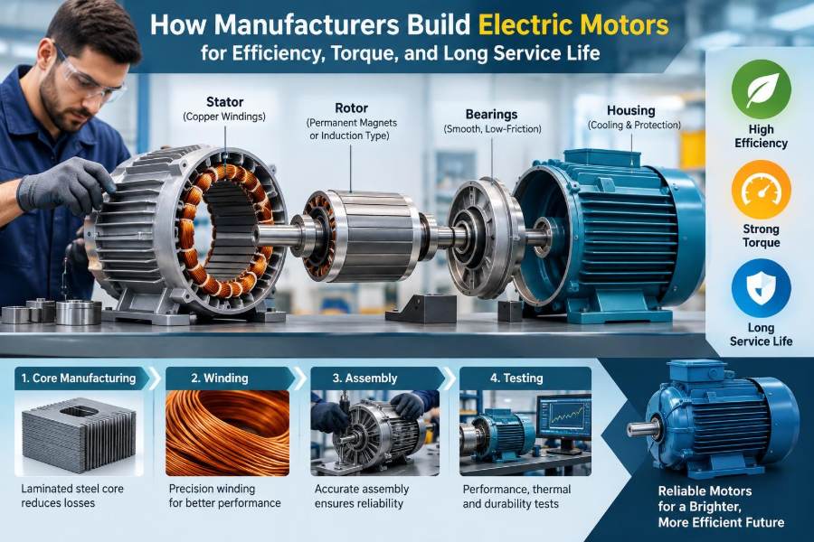

A factory conveyor starts smoothly at the beginning of a shift. A heat-pump fan runs quietly through the night. An electric vehicle pulls away from a traffic light without a gear change. In each case, an electric motor is doing more than simply spinning: it is converting electrical energy into controlled mechanical work.
That conversion looks deceptively simple from the outside. Behind the housing, however, manufacturers must make connected decisions about steel, copper, magnets, insulation, cooling, bearings, machining, and electronic control.
A motor that produces high torque may still disappoint if it overheats, wastes energy at normal load, creates objectionable noise, or wears out its bearings early. Conversely, an exceptionally efficient design may not be the right choice if it cannot survive dust, vibration, repeated starting, or a demanding production process.
Understanding how motors are built makes specification sheets more meaningful and helps engineers diagnose real equipment problems. The central challenge is not maximizing one number. It is balancing performance, manufacturability, cost, and service life for the job the motor must do.
🔄 Start with the Energy Conversion Job
An electric motor creates torque through magnetic fields. Current in conductors produces a magnetic field, and that field interacts with another field in the motor to create a turning force on the rotor.
In practical terms, the stator is the stationary magnetic structure and the rotor is the rotating member. The design goal is to produce useful torque with as little unwanted heat, vibration, and magnetic loss as possible.
Manufacturers begin with the driven load. A pump, fan, compressor, hoist, robot joint, and traction wheel have very different torque-speed requirements, so they should not receive the same motor design by default.
📋 Define the Duty Before Choosing Materials
Duty describes how a motor operates over time: continuous running, intermittent cycling, frequent starts, reversing, overloads, or long idle intervals. A motor that is adequate for a steadily running fan can overheat quickly when used to accelerate a high-inertia conveyor every few seconds.
Designers also establish the supply voltage, frequency or inverter range, speed target, ambient temperature, altitude, installation space, and required protection against water or dust. These inputs set the boundaries for the electromagnetic and mechanical design.
- Continuous duty emphasizes steady-state losses and cooling.
- Start-stop duty emphasizes peak current, rotor heating, and mechanical fatigue.
- Variable-speed duty adds inverter switching effects and a broad operating map.
- Safety-critical duty may require monitoring, redundancy, or conservative thermal margins.
🧭 Select the Motor Topology
There is no universally best electric motor. Manufacturers select a topology based on the application’s speed range, control needs, cost constraints, supply arrangement, and environment.
| Motor type | Useful strengths | Common design trade-off |
|---|---|---|
| Induction motor | Rugged rotor, broad industrial use, no rotor magnets | Rotor losses and magnetizing current affect efficiency |
| Permanent-magnet synchronous motor | High torque density and strong efficiency potential | Magnet cost, temperature limits, and control complexity |
| Switched reluctance motor | Simple robust rotor and high-speed capability | Torque ripple and acoustic noise need careful management |
| Brushed DC motor | Simple speed control and strong starting torque | Brush and commutator wear limit maintenance-free life |
The choice changes every later manufacturing decision. A permanent-magnet rotor needs accurate magnet placement and secure retention, while an induction rotor requires a conductive cage that is cast or fabricated reliably.
📐 Size the Electromagnetic Circuit
Motor dimensions are not chosen just to fit a housing. The bore diameter, stack length, air-gap size, slot shape, and pole count control how much magnetic flux and current loading the motor can support.
A larger active volume can generally produce more torque, but it adds weight, material cost, and sometimes rotational inertia. Designers seek enough magnetic and electrical loading to meet the requirement without pushing steel into excessive saturation or copper into excessive heat.
Torque is closely related to the interaction between air-gap flux and stator current. That is why the tiny clearance between stator and rotor is one of the most influential dimensions in the entire machine.
🧲 Use Electrical Steel to Guide Flux
The stator core and, in many designs, the rotor core are made from thin sheets of electrical steel called laminations. Their job is to provide a low-reluctance path for magnetic flux, much as a well-shaped channel guides flowing water.
Using one solid steel core would encourage circulating currents within the metal when flux changes. Those eddy currents waste energy as heat. Insulated lamination sheets interrupt the current paths and greatly reduce this loss.
Steel selection involves a balance between magnetic loss, saturation behavior, strength, thickness, availability, and cost. Higher-frequency operation usually makes core-loss control more demanding because the magnetic field reverses more often.
🏭 Stamp, Stack, and Lock the Laminations
Manufacturers stamp laminations from steel coil using precision tooling. The stamped geometry includes teeth, slots, ventilation features, alignment holes, and sometimes interlocking tabs.
Small burrs created during stamping deserve attention. If burrs bridge insulation between sheets, they can form local electrical paths that raise iron loss. Tool wear and handling therefore affect efficiency, not merely appearance.
Laminations are stacked to the specified length and secured by welding, bonding, interlocking, clamping, or a combination of methods. The assembly method must hold the core rigidly without damaging insulation or creating distortion that complicates winding insertion.
🌀 Design Slots and Windings Together
Stator slots hold insulated copper or aluminum conductors. Their shape influences how much conductor fits, how easily coils can be installed, how well heat reaches the core, and how the air-gap field is distributed.
More copper cross-sectional area lowers winding resistance, reducing I²R loss: heat generated when current flows through resistance. Yet tightly packed slots can be difficult to wind and impregnate, and they may limit cooling paths.
Winding layout also shapes torque smoothness, harmonic losses, noise, and the voltage required at a given speed. A seemingly minor change in coil pitch or number of turns can move several performance characteristics at once.
🧵 Form Coils Without Damaging Insulation
For high-volume products, coils may be wound on automated equipment before insertion. Other designs use needle winding directly into stator slots. Large machines may use carefully formed coils installed by skilled processes.
Copper is repeatedly bent, pulled, and compressed during manufacture. The enamel coating on magnet wire is thin, so sharp edges, excessive tension, or poor tooling can create damage that does not immediately cause a failure.
Manufacturers control wire placement, coil shape, and end-winding length. End windings do not contribute directly to torque, but they add resistance, occupy space, and must withstand electromagnetic forces and vibration.
🛡️ Build an Insulation System, Not Just a Wound Stator
A reliable winding depends on layers of insulation: wire enamel, slot liners, phase separators, sleeves, wedges, lacing, and varnish or resin. Together these materials form the insulation system.
Its purpose is to prevent turn-to-turn, phase-to-phase, and winding-to-ground faults under electrical, thermal, mechanical, and environmental stress. A winding can pass an initial electrical test yet fail early if its insulation rubs, cracks, absorbs moisture, or ages too rapidly in heat.
Temperature capability is a system property. The limiting material may be the slot liner, impregnation resin, lead insulation, or a connection point rather than the copper wire itself.
💧 Impregnate Coils to Improve Heat Flow and Stability
After winding, many stators are dipped, trickle-impregnated, or vacuum-pressure impregnated with varnish or resin. The material fills voids, bonds conductors, and helps transfer heat from the winding toward the core and frame.
Good impregnation also reduces wire movement. That matters because electromagnetic forces can make loosely supported conductors vibrate, gradually wearing insulation and producing an audible hum.
More resin is not automatically better. The process must achieve penetration without blocking intended ventilation paths, creating excessive buildup, or introducing cure-related stress.
⚙️ Manufacture the Rotor for Its Specific Physics
Rotor construction depends strongly on motor type. In an induction motor, rotor laminations contain slots filled by conductive bars joined by end rings, creating the familiar squirrel-cage structure.
Many induction rotors use die-cast aluminum cages. This process must fill narrow slots consistently and avoid defects that increase resistance or create imbalance. Copper cages can reduce electrical resistance in some designs but are more challenging to manufacture.
Permanent-magnet rotors require accurately positioned magnets, adhesive or mechanical retention, and protection from corrosion. At high speed, retention is a safety issue: centrifugal force can be substantial, so sleeves or bands may be engineered into the rotor.
🧲 Manage Magnets, Demagnetization, and Temperature
Permanent magnets offer strong air-gap flux without continuous rotor current, which can support compact and efficient machines. But magnets are not interchangeable blocks of performance.
Temperature, opposing magnetic fields, mechanical shock, and material grade affect magnetic behavior. A manufacturer must ensure that expected current and fault conditions do not push the magnet operating point into harmful demagnetization.
Magnet placement also changes the motor’s character. Surface-mounted magnets simplify some rotor geometries, while interior magnets can enable useful saliency torque and stronger mechanical protection. Both approaches involve compromises in control, manufacturing, and field distribution.
🎯 Hold a Precise Air Gap
The air gap is the clearance between the stator and rotor. It must be small enough for effective magnetic coupling, yet large enough to avoid contact under tolerance variation, thermal expansion, shaft deflection, bearing play, and vibration.
An excessively large gap demands more magnetizing effort and can weaken torque capability. An excessively small gap raises the risk of rubbing, noise, and damage during transients.
Machining accuracy, concentric assembly, bearing-seat geometry, and rotor balance all contribute to maintaining this clearance. Efficiency and durability can therefore depend on mechanical precision as much as electromagnetic calculations.
🔥 Trace Every Source of Heat
A motor’s losses become heat, and temperature is often the main factor limiting continuous output. Manufacturers construct a loss budget rather than treating heat as a single quantity.
- Copper loss: resistance heating in stator conductors and, where applicable, rotor conductors.
- Core loss: hysteresis and eddy-current loss in magnetic steel.
- Mechanical loss: bearing friction, windage, seals, and fan power.
- Stray load loss: additional loss from leakage flux, harmonics, and nonideal current distribution.
Losses vary with speed, torque, voltage, and control method. A motor may be highly efficient near its intended operating point but less favorable when lightly loaded or driven far from its design speed.
🌡️ Create a Reliable Thermal Path
Heat must move from copper and core to the surrounding environment. The path may include resin, insulation, steel, housing, cooling fins, air channels, liquid jackets, and a fan.
Air cooling is simple and common, but dust buildup can insulate fins and restrict airflow. Liquid cooling can remove heat more effectively in a compact machine, yet it adds seals, channels, connections, and system-level failure modes.
Thermal models guide design, but validation matters because contact resistance, manufacturing variation, airflow patterns, and installation details can change actual temperatures. Sensors are often placed where overheating is expected, though no one sensor represents every internal hot spot.
🌀 Balance the Rotor and Control Vibration
Any uneven mass distribution around a rotor creates centrifugal force as speed rises. Dynamic balancing corrects this condition by measuring imbalance and removing or adding small amounts of mass at defined locations.
Balance is not merely about a smoother feel. Vibration loads bearings, loosens connections, accelerates fatigue, and can create noise that customers interpret as poor quality.
The assembled system matters too. A well-balanced rotor can still vibrate when mounted on a flexible base, coupled to a misaligned load, or operated near a structural resonance.
🔩 Choose Bearings for Load, Speed, and Environment
Bearings locate the rotor, carry radial and axial loads, and preserve the air gap. Rolling-element bearings are widely used because they are compact and practical, but their performance depends on lubrication, cleanliness, fit, preload or clearance, and shaft alignment.
High radial load, belt tension, thrust load, shock, high speed, and high ambient temperature all change the bearing choice. Some machines use sleeve bearings where their damping and load characteristics suit the application.
Bearing life is statistical rather than a promise for each individual unit. A correct design improves the expected outcome, but contamination, installation force applied through rolling elements, electrical discharge, and poor lubrication can shorten life dramatically.
⚡ Prevent Inverter-Related Bearing Damage
Variable-frequency drives allow precise speed and torque control, but their fast switching voltage edges can create common-mode voltages in the motor. In some installations, shaft voltage can discharge through bearings and damage race surfaces over time.
Manufacturers may use insulated bearings, shaft grounding devices, conductive grease approaches, or system-level filtering depending on machine size and drive arrangement. The right measure depends on the complete motor-cable-drive system.
This is a useful reminder that a motor cannot always be evaluated in isolation. Cable length, grounding, switching settings, and driven equipment can alter electrical stress in ways a basic nameplate does not reveal.
🔊 Design Out Noise Where Possible
Motor noise may come from aerodynamic fan noise, bearings, mechanical looseness, gearboxes, or electromagnetic forces. Magnetic forces can excite the stator teeth and housing at frequencies linked to electrical supply, switching, and slot-pole interactions.
Designers reduce noise through winding choices, slot and pole combinations, skewing, stiff structures, careful air-gap geometry, and tuned control strategies. No single technique is free: skewing, for example, can smooth torque but may alter torque capability and manufacturing complexity.
Acoustic testing should reflect use conditions. A motor that sounds acceptable on an isolated test stand can become intrusive when its mounting panel acts like a loudspeaker.
🧠 Match the Motor to Its Controller
Modern motor performance is often co-designed with electronics. The controller measures or estimates rotor position and current, then commands phase currents to create the desired torque.
For an inverter-fed motor, the voltage waveform is not a perfect sine wave. Pulse-width modulation creates switching harmonics that influence insulation stress, acoustic behavior, losses, and electromagnetic interference.
Control software can improve efficiency by selecting suitable current vectors at different loads, but it cannot erase physical limits. The motor needs enough thermal capacity, voltage margin, sensor quality or estimation robustness, and fault protection for its actual duty.
📈 Read the Efficiency Map, Not Only the Peak
A single efficiency value is useful but incomplete. Real machines operate across ranges of speed and torque, so engineers often examine an efficiency map showing where losses are lowest and where they rise.
Consider a hypothetical pump that spends most of its time at moderate speed and partial load. Choosing a motor solely because it has an excellent peak efficiency near rated load may not minimize energy use over the pump’s actual schedule.
Part-load behavior, standby losses in the drive, fan power, and the driven process all matter. System efficiency is the useful outcome, not a trophy number for one component.
🧰 Design the Housing and Sealing for the Workplace
The frame supports the core, transfers heat, protects internal parts, and provides mounting surfaces. Cast, fabricated, or extruded housings each offer different opportunities for cooling fins, stiffness, weight control, and manufacturing cost.
Ingress protection must match the environment. Dust, washdown water, corrosive vapors, salt exposure, and outdoor temperature cycling call for different seals, coatings, drains, cable entries, and breathing arrangements.
More sealing can protect against contaminants but may reduce passive cooling or complicate service. A suitable enclosure is therefore an application decision, not simply a higher-is-better feature.
🧪 Test Electrical Integrity During Production
Production testing catches defects before a motor reaches equipment assembly. Typical checks include winding resistance, phase balance, insulation resistance, dielectric withstand testing, and verification that connections are correct.
Some tests target manufacturing defects; others verify final functional behavior. A no-load run can reveal abnormal current, noise, vibration, or rubbing, while back-electromotive-force measurements may help assess magnetized machines.
Test voltage, duration, and acceptance criteria must be appropriate for the product and insulation system. Overly aggressive testing can itself stress insulation, while weak testing may miss faults that emerge during operation.
📊 Validate Torque, Temperature, and Speed
Development and sample validation usually go beyond end-of-line checks. Dynamometers apply controlled load so engineers can measure torque, speed, input power, efficiency, and thermal rise across the intended operating range.
Temperature testing needs time. Heavy copper and steel structures can take a long time to reach thermal equilibrium, and short tests may hide an eventual hot spot.
Results are interpreted with engineering judgment. Differences between a prototype and production unit may arise from material batches, fit tolerances, impregnation quality, cooling hardware, or controller calibration.
🧱 Qualify for Vibration, Moisture, and Repeated Cycling
Long service life is challenged by conditions that a smooth bench test may not reproduce. Vibration can fatigue leads and loosen hardware; moisture can reduce insulation resistance; thermal cycling can stress bonds and connections.
Manufacturers use environmental and durability evaluations appropriate to the market and product risks. The goal is not to assume every motor faces every hazard, but to expose credible weak points before broad production.
Accelerated tests are informative rather than magical forecasts. Raising temperature or cycling rate may reveal failure mechanisms, yet real-life outcomes still depend on installation, maintenance, and operating conditions.
🏗️ Engineer for Repeatable Assembly
A clever prototype is not automatically a manufacturable motor. Production design needs tolerances that suppliers and assembly equipment can repeatedly achieve, along with inspection methods that detect meaningful deviation.
Design for manufacturability may simplify lead routing, make coil insertion less damaging, reduce the number of fasteners, or provide clear fixtures for aligning parts. These changes can improve quality as well as labor time.
Traceability is also valuable for critical products. Recording material lots, test outcomes, and process settings can help isolate root causes if a field issue appears later.
🔧 Avoid Common Specification Mistakes
Many motor problems begin before purchase. Selecting only by rated power overlooks speed, torque, starting duty, cooling conditions, control method, and the load’s inertia.
- Do not assume a motor designed for mains operation will behave identically on an inverter.
- Do not treat nominal torque as proof that acceleration torque is adequate.
- Do not ignore reduced cooling at low speed when a shaft-mounted fan slows down.
- Do not oversize blindly; a large motor can operate inefficiently at a very light load.
- Do not overlook mounting alignment, cable practices, and enclosure ventilation.
A clear duty profile and a complete system view prevent many expensive “motor failures” that are actually application mismatches.
🧰 Protect Motor Life After Installation
Even a carefully built motor benefits from correct commissioning. Verify rotation direction, mounting tightness, alignment, grounding, cooling airflow, terminal torque, and controller limits before placing equipment into demanding service.
Condition monitoring can be simple: trend operating current, bearing noise, housing temperature, vibration, and insulation condition where practical. A changing trend often provides more useful warning than one isolated reading.
Maintenance should target the actual design. Sealed-for-life bearings, regreaseable bearings, filtered ventilation paths, and liquid-cooling loops need different service practices. Adding lubricant indiscriminately, for example, can cause as many problems as too little lubrication.
✅ The Core Principle: Optimize the Whole Motor System
Efficient, high-torque, long-lived motors emerge from coordinated choices, not a single premium material or manufacturing trick. Copper, steel, air-gap geometry, rotor design, insulation, cooling, bearings, controls, and quality checks must support one another.
The most successful design is the one that delivers the required torque and speed across its real duty cycle while keeping losses, temperature, noise, stress, and production variation within acceptable limits. That is why motor engineering remains an exercise in disciplined trade-offs.
For students, this perspective connects electromagnetics to materials, mechanics, manufacturing, and power electronics. For working professionals, it provides a practical lens for asking better questions when selecting, testing, or troubleshooting a motor.
A durable electric motor is built by treating efficiency, torque, heat removal, mechanical precision, and real operating conditions as one connected engineering problem. ⚡🔧🌀