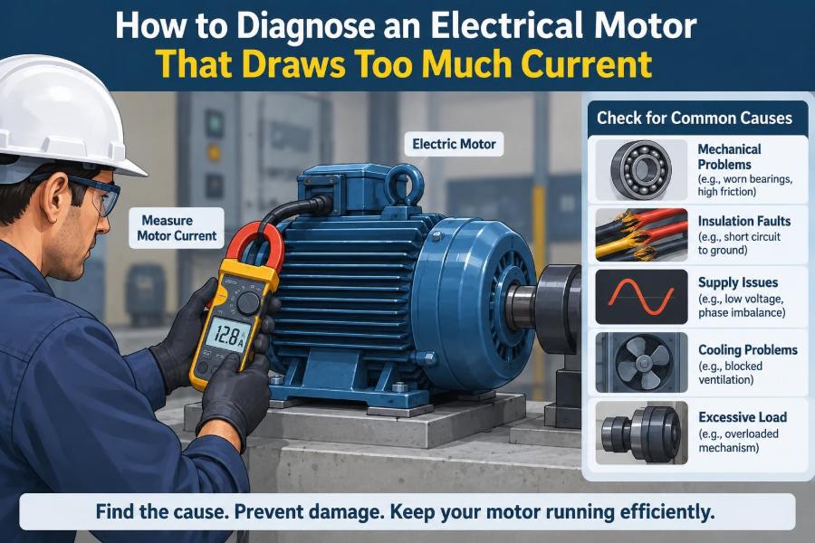

A motor that draws too much current rarely announces the cause plainly. A conveyor slows after a bearing replacement, a pump trips its overload on hot afternoons, or a fan motor runs for ten minutes before its starter opens. The immediate temptation is to blame the motor.
Sometimes the motor is at fault. Just as often, however, excessive current is the symptom of a mechanical load, poor supply conditions, incorrect connections, or a control-system problem. Replacing the motor without finding the source can turn a short repair into a recurring failure.
Current is one of the most useful clues available to an electrical technician. It reveals how hard the motor is working, but it must be interpreted alongside voltage, speed, temperature, sound, and the driven equipment.
The safest diagnosis follows a sequence: confirm the measurement, compare it with the motor’s rating and operating condition, then separate electrical causes from mechanical ones. That approach protects people, equipment, and production time.
🧭 Start With a Clear Definition of “Too Much”
“High current” can mean different things. A motor naturally draws a brief, large starting or inrush current while it accelerates. A normal induction motor may draw several times its full-load current during starting, and that is not automatically a defect.
The concern is sustained running current that exceeds the value on the nameplate, an overload relay setting appropriate to that nameplate, or a known normal operating baseline. A motor can also be in trouble when one phase current is much higher or lower than the others, even if the average seems acceptable.
🏷️ Read the Nameplate Before Testing
The nameplate is the starting reference, not a decorative label. Record rated voltage, full-load current (FLA), frequency, phase arrangement, rated speed, power, service factor if listed, insulation class, duty rating, and connection diagram.
Do not compare a measured line current with an unrelated value such as a breaker rating. A protective device may be intentionally larger than the motor’s FLA to tolerate starting, while overload protection is selected to protect the motor winding under running overload conditions.
- Confirm whether the motor is rated for one voltage or multiple voltages.
- Check whether it is intended for 50 Hz, 60 Hz, or both.
- Verify its stated connection: wye/star, delta, series, or parallel.
- Note whether a variable-frequency drive (VFD) supplies the motor.
🦺 Make the Investigation Safe
Live motor measurements expose workers to hazardous energy, rotating parts, and arc-flash risk. Only qualified people using the site’s electrical safety procedures, suitable PPE, and properly rated instruments should perform energized tests.
For mechanical inspection, use lockout/tagout, verify the isolation, and wait for rotating parts to stop. A VFD may retain hazardous DC-bus voltage after incoming power is removed, so follow the manufacturer’s discharge and verification instructions rather than assuming it is safe immediately.
📏 Verify the Current Measurement
A misleading measurement can send the entire diagnosis in the wrong direction. Use a true-RMS clamp meter suitable for the waveform being measured, especially on VFD-fed circuits where current is not a clean sine wave.
Clamp around one conductor only. Clamping around all phase conductors together makes their magnetic fields largely cancel, giving a near-zero reading. Measure each phase at the same operating condition and allow the load to stabilize before recording values.
Also check the meter’s range, battery condition, and jaw closure. When results appear surprising, compare with a second known-good meter or repeat the measurement at a different accessible point in the circuit.
📊 Record a Useful Baseline
A single amperage value is less useful than a small operating snapshot. Record phase currents, line-to-line voltages, motor surface temperature trend, ambient temperature, load condition, operating speed or process output, and any unusual vibration or sound.
For example, a pump drawing 108% of nameplate current while delivering unusually high flow suggests a different path than a pump drawing the same current while producing poor flow and making a grinding noise. Context turns a number into evidence.
⚖️ Compare All Three Phase Currents
On a three-phase motor running normally, the three line currents should be reasonably similar. The exact acceptable difference depends on the equipment and supply, but a pronounced imbalance deserves investigation before the motor is damaged.
A simple field screening calculation is current unbalance: find the average of the three currents, find the largest deviation from that average, divide by the average, and multiply by 100. This is a diagnostic indicator, not a substitute for applicable manufacturer guidance or site standards.
| Observed pattern | Likely direction to investigate |
|---|---|
| All three currents high and similar | Mechanical overload, low voltage, incorrect frequency/speed command, or undersized motor |
| One current markedly high or low | Voltage imbalance, bad connection, winding issue, or partial phase loss |
| All currents low but motor overheats | Cooling failure, high ambient temperature, incorrect VFD setup, or internal fault |
| High current only during acceleration | Starting method, excessive inertia, jammed load, or too-short start limit |
🔌 Measure Voltage at the Motor Terminals
Voltage should be checked while the motor is operating, ideally at its terminals or as close to them as safely practical. A voltage measured at a distant panel can look acceptable while a loose lug, damaged contactor, or undersized feeder causes a significant drop at the motor.
Measure all line-to-line combinations on a three-phase circuit: L1-L2, L2-L3, and L3-L1. Compare both their average level with the nameplate voltage and their balance with one another. Record which current corresponds to each line while tracing a suspected connection problem.
⚡ Understand Why Low Voltage Raises Current
For a motor driving roughly the same mechanical load, lower supply voltage tends to require more current to produce the required torque and power. The motor may slip more, run hotter, and eventually stall or trip an overload if the voltage reduction is severe enough.
The relationship is not perfectly linear in real machines. Motor torque, saturation, load type, and supply quality all matter. Still, low voltage at the terminals is a credible explanation for high current and should never be dismissed because the upstream supply “looks close enough.”
📉 Treat Voltage Unbalance as a Serious Clue
A relatively small voltage imbalance can create a much larger current imbalance in an induction motor. The resulting negative-sequence magnetic field opposes normal rotation and produces additional heating in the rotor and stator.
Causes include uneven single-phase loading upstream, a weak transformer connection, a blown fuse on one line, a high-resistance contactor pole, or a loose terminal. Correct the voltage or connection fault first; simply increasing the overload setting hides the symptom while allowing damaging heat to continue.
🧯 Look for Partial Phase Loss and Bad Connections
A completely open phase often causes a stopped motor to hum and fail to start, but partial phase loss can be subtler. A corroded fuse clip, burned contactor contact, loose lug, or damaged cable may introduce enough resistance to distort voltage and current under load.
With power isolated, inspect for discoloration, melted insulation, pitted contactor faces, loose hardware, and heat-damaged terminals. Under controlled energized conditions, qualified personnel may use voltage-drop tests or thermal imaging to locate a high-resistance joint. Never tighten or disturb energized connections.
🔗 Confirm the Motor Is Connected for the Applied Voltage
Many dual-voltage motors can be connected in series for a higher voltage or parallel for a lower voltage. A motor incorrectly connected for the supply can draw excessive current, develop poor torque, or fail quickly.
Use the diagram on the motor, not memory or a generic internet diagram. Lead markings, terminal-board arrangements, and design conventions vary. Also verify that replacement leads were returned to the correct terminals after rewinding, repair, or a recent control-panel modification.
🌀 Separate Starting Current From Running Current
Starting is a demanding event. The motor must accelerate its rotor and the driven load while overcoming friction and any process resistance. If acceleration takes too long, high starting current persists long enough to overheat the motor or trip the protective device.
Observe when the current is high: only at start, throughout acceleration, or after reaching speed. A motor that starts normally but overloads after a valve opens points toward the process load. A motor that never reaches speed points toward a jam, insufficient starting torque, phase problem, or inappropriate starting arrangement.
🏭 Check Whether the Mechanical Load Is Excessive
If all phase currents are high and balanced while terminal voltage is healthy, the motor may simply be doing more work than it was selected to do. Mechanical overload is often the most direct explanation for persistent high current.
Common examples include a conveyor carrying more material than expected, a blower with excessive air flow, a compressor operating at elevated pressure, a pump moving a fluid with changed viscosity, or a mixer handling a thicker batch. Electrical tests alone cannot identify every process change.
🛞 Inspect Bearings, Alignment, and Couplings
Worn or poorly lubricated bearings add friction. Misalignment between motor and driven shaft imposes side loads and can cause vibration, coupling wear, and elevated current. A coupling that has been installed too tightly or a belt that is over-tensioned can create the same effect.
After safe isolation, turn the shaft by hand when the design permits. It should rotate smoothly, though this is only a coarse check. Bearing damage may become evident only at operating speed, where vibration analysis, temperature trends, and acoustic observations provide stronger evidence.
🧱 Rule Out a Jammed or Bound Driven Machine
A blocked pump, seized gearbox, obstructed fan, material buildup, or damaged conveyor roller can raise torque dramatically. The motor responds by drawing more current in an attempt to maintain speed; if torque demand exceeds available torque, it slows or stalls.
Where safe and permitted, decouple the motor from the load and perform a brief no-load test. A substantial reduction in current points to the driven equipment. Do not run an uncoupled motor beyond what the manufacturer and machine arrangement allow, and secure all exposed rotating components.
🌬️ Recognize Fan and Pump Load Laws
Centrifugal fans and pumps have a special behavior: their torque demand tends to rise approximately with the square of speed, while power demand rises approximately with the cube of speed. A modest overspeed command can therefore create a surprisingly large current increase.
This matters after pulley changes, fan-damper changes, impeller trimming errors, or VFD commissioning. A hypothetical fan moved from a conservative speed setting to near base speed may cross the motor’s loading limit even though nothing is mechanically broken.
💧 Investigate Pump System Changes
Pump current should be interpreted with the pump curve and system condition in mind. A valve left open, reduced piping resistance, a larger impeller, or a liquid with different density can move the pump to a higher-flow operating point and increase power demand.
Conversely, cavitation often produces noise and vibration, but its effect on current is not universal enough to diagnose from amperage alone. Check suction conditions, discharge pressure, flow indication where available, valve positions, and evidence of blockage or air ingress.
🪢 Examine Belt Drives and Gearboxes
Belt-driven equipment introduces variables that direct-coupled motors do not have. Excessive belt tension raises bearing load; slipping belts can create heat and poor output; incorrect pulley sizes can increase speed and load beyond the motor’s capability.
Gearboxes add lubrication condition, gear damage, and ratio verification to the inspection. A gearbox that feels unusually hot or produces rhythmic noise should not be treated as an electrical problem merely because the motor overload is the device that trips first.
🌡️ Connect Current, Heat, and Insulation Life
Winding heating rises rapidly as current increases because copper losses follow an approximate I²R relationship: doubling current produces roughly four times the resistive heating in the same winding resistance. That is why a modest sustained overload can matter.
Current is not the only source of damaging temperature. Blocked cooling paths, failed fans, high ambient temperature, high altitude, frequent starts, and VFD harmonic effects can all reduce thermal margin. A motor may run within nameplate current yet still overheat if cooling conditions are poor.
🧊 Check the Cooling System
Inspect external cooling fins, air passages, shrouds, and the shaft-mounted fan. Dirt, fiber, paint buildup, or a missing fan can prevent heat from leaving the frame. On separately ventilated motors, confirm the independent blower operates in the correct direction.
A hot motor frame is a warning, not a complete diagnosis. Surface temperature depends on where it is measured and on ambient conditions. Trending temperatures at comparable locations and loads is more useful than treating one infrared reading as an absolute winding temperature.
🧪 Use Insulation Tests at the Right Time
Insulation resistance testing can help identify moisture, contamination, or insulation deterioration, but it does not directly prove why a motor draws high running current. Perform it only with the motor properly isolated from drives, controls, surge devices, and other equipment that could be damaged by test voltage.
Interpret results according to the motor manufacturer’s instructions and established maintenance procedures, including temperature correction where applicable. A low reading demands investigation; a high reading does not clear the motor of winding turn-to-turn faults, mechanical trouble, or supply problems.
🧲 Consider Winding Faults Carefully
Shorted turns, phase-to-phase faults, and damaged rotor bars can alter current, torque, vibration, and temperature. Some faults are obvious, while others appear only under load or as a developing trend. A basic clamp-meter reading cannot identify every internal motor defect.
Useful specialist methods may include winding resistance comparison, surge testing, motor circuit analysis, insulation tests, vibration analysis, and current signature analysis. Test selection should match the symptom and the motor’s importance; invasive or high-energy tests require trained personnel and suitable equipment.
🔧 Do Not Ignore the Rotor
In squirrel-cage induction motors, rotor defects can cause reduced torque, speed pulsation, increased slip, vibration, and abnormal current behavior. Cracked rotor bars and poor end-ring connections are examples, particularly in machines subject to frequent starts or severe duty.
These faults can be difficult to confirm in the field. If supply voltage is balanced, the mechanical load is reasonable, and the motor still shows unexplained heating or torque loss, escalation to a motor-repair specialist may be more productive than repeated adjustment of controls.
🎛️ Diagnose VFD-Fed Motors Differently
A VFD changes the diagnostic picture. It controls motor frequency and voltage, reports estimated current, and may limit acceleration or torque. Its display is useful, but measurements should be interpreted with the drive manual and the motor’s inverter-duty suitability in mind.
Check commanded frequency, acceleration time, current limit, motor nameplate data entered into the drive, control mode, and any torque boost setting. An overly aggressive boost or incorrect motor parameters can raise low-speed current and heating. Measure input and output only with instruments rated for the task.
📐 Verify Frequency and Speed
Motor synchronous speed depends on supply frequency and pole count. If a process has been moved from 50 Hz to 60 Hz, or a VFD command exceeds the intended base speed, the driven load may demand more power than the motor can safely supply.
Compare actual shaft speed, where safely measurable, with expected speed. Excessive slip can indicate overload, low voltage, rotor trouble, or an incorrect frequency setting. A tachometer is often more revealing than trying to infer speed from sound alone.
🧷 Review Overload Protection Settings
An overload relay should be set and selected according to the motor nameplate, starting characteristics, service conditions, and applicable installation requirements. It is designed to protect against sustained overload, not to compensate for a motor that was selected too small or a machine that has become hard to turn.
Repeated trips are data. Resetting the relay or increasing its setting before finding the cause can allow winding temperature to climb. At the same time, a relay set too low can nuisance-trip a healthy motor, so verify settings rather than assuming either the motor or relay is wrong.
🗂️ Follow a Practical Diagnostic Sequence
A consistent order prevents unnecessary disassembly and avoids overlooking simple faults. Begin with observations that preserve the operating condition, then move toward isolated mechanical and electrical tests.
- Confirm the complaint and determine whether the high current occurs at start, during run, or under a specific process condition.
- Read the nameplate and verify connection, supply type, and control method.
- Measure and record all phase currents and line-to-line voltages under load.
- Inspect for imbalance, voltage drop, heat damage, poor connections, and cooling obstruction.
- Evaluate the driven machine: load, alignment, bearings, belts, gearbox, pump, fan, or process conditions.
- Isolate or decouple only when safe, then compare no-load behavior with loaded behavior.
- Escalate to insulation, winding, rotor, vibration, or drive-specific tests when basic checks do not explain the evidence.
🚫 Avoid Common Diagnostic Shortcuts
Several shortcuts create expensive mistakes. Replacing the motor because the overload tripped, raising the overload setting because production is waiting, or checking voltage only with the motor stopped can all conceal the real fault.
- Do not assume balanced current means the motor is healthy; balanced mechanical overload is common.
- Do not assume a cool frame means cool windings; internal heating can develop first.
- Do not judge load from sound alone; measure current, voltage, and speed.
- Do not disconnect a VFD output or megger a connected drive without following its instructions.
- Do not use a no-load current value from a different motor as a universal pass/fail limit.
📝 Build a Trend Instead of Chasing One Reading
For critical equipment, record current, voltage, temperature, vibration, and process output at regular intervals. A gradual rise in current on a conveyor, for instance, may reveal bearing deterioration or increasing material resistance before a trip stops the line.
Trending is especially valuable because motors differ. The best comparison is often the same motor operating under the same known-good conditions, not a generic number taken from another installation.
👷 Know When to Call for Specialist Support
Escalate when there is evidence of arcing, repeated protection trips, abnormal vibration, insulation concerns, suspected internal winding or rotor faults, or a VFD fault that cannot be resolved from documented parameter checks. High-energy systems and large motors justify a careful, coordinated response.
A motor shop, reliability technician, drive manufacturer, or qualified electrician may have tools and experience beyond routine field checks. Provide them with recorded currents, voltages, operating conditions, photos of connections, fault histories, and recent equipment changes; good records shorten the investigation.
✅ The Core Principle: Diagnose the System, Not Just the Motor
Excessive current is the motor’s response to conditions around it. It may be responding to a heavier mechanical load, lower or unbalanced voltage, a poor connection, incorrect configuration, restricted cooling, or an internal defect.
The most reliable answer comes from correlating measurements. High, balanced current with healthy voltage points toward load; current imbalance directs attention to supply, connections, or windings; a normal current reading with high temperature shifts focus toward cooling and duty. Each clue narrows the possibilities without making assumptions.
When a motor draws too much current, measure carefully, compare against the nameplate and operating context, and correct the cause rather than merely resetting the protection. That method keeps a small warning from becoming an avoidable motor failure. ⚡🔧🛠️