
A space heater runs for an hour without trouble, yet the plug feels unusually warm when it is removed. A kitchen circuit keeps supplying power, but a faint hot-plastic smell appears near one outlet. In a panel, one cable looks discoloured even though no breaker has moved to the OFF position.
These situations seem contradictory. If a cable is getting hot, surely the circuit breaker should trip first. But a breaker does not directly measure cable temperature at every point along a circuit. It responds mainly to current, and only within the limits of its particular trip mechanism.
That distinction matters in homes, workshops, commercial buildings, and industrial systems. Local overheating can damage insulation, weaken connections, and create fire hazards long before current becomes high enough, or stays high enough, to operate the breaker.
Understanding the gap between overcurrent protection and temperature control makes electrical faults easier to recognize and safer to investigate.
⚡ A breaker is not a cable thermometer
A circuit breaker is designed to interrupt a circuit when current exceeds a safe level for a sufficient time, or when a very large fault current occurs. It is not a sensor attached to every conductor, terminal, splice, plug, or cable bundle.
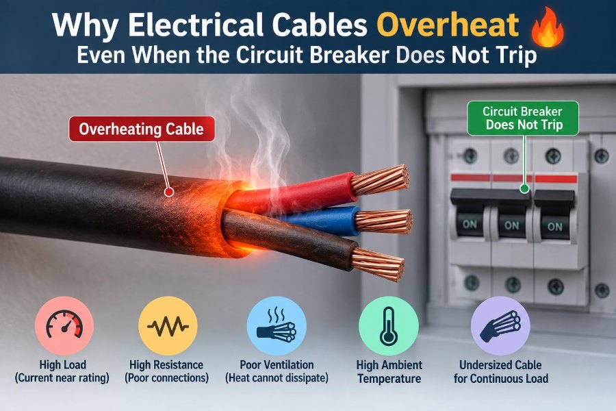
A cable can therefore overheat at one small location while the overall circuit current remains normal. The breaker may be operating exactly as designed, even though a poor connection or unsuitable installation is developing excessive heat.
🔌 The basic source of cable heating
Conductors have resistance. When current passes through that resistance, electrical energy is converted into heat. The relationship is commonly written as P = I²R, where P is heating power, I is current, and R is resistance.
The square on current is especially significant. Doubling current produces four times the resistive heating in the same resistance. Yet resistance can also rise locally at a bad joint, producing substantial heat even at an ordinary load current.
🧭 What the breaker actually senses
Most conventional breakers use thermal and magnetic trip functions. The thermal element responds gradually to sustained overcurrent; the magnetic element responds rapidly to a severe short circuit or ground fault.
Neither mechanism identifies where heat is occurring. A breaker may sense 12 A flowing through a branch circuit, while a loose terminal carrying that same 12 A becomes the hottest point in the entire installation.
⏱️ Trip curves allow normal short-term demand
Breakers intentionally do not trip at the exact instant current reaches the number printed on their handle. Loads such as motors, transformers, and power supplies may draw a temporary starting or inrush current that is higher than their normal running current.
Trip curves define how long a breaker can carry different levels of overcurrent. This delay is useful, but it means a modest overload can heat conductors for some time before interruption occurs. The permitted duration depends on the breaker type, rating, ambient temperature, and fault level.
📏 Cable ampacity is an installation rating
Ampacity is the current a conductor can carry under stated installation conditions without exceeding its allowable temperature limit. It is not merely a property of copper or aluminum size.
The same conductor may have a different permitted ampacity when installed in open air, inside conduit, in insulation, underground, or grouped with many other loaded cables. A breaker selected without considering those conditions can fail to protect the cable’s real thermal environment.
🌡️ Ambient temperature changes the margin
Cable ratings are based on specified surrounding temperatures. A cable routed through a hot ceiling void, beside a boiler pipe, near process equipment, or inside a sun-heated enclosure starts closer to its temperature limit.
The load current may be unchanged and still be acceptable on a cool day but problematic in a hotter location. Breakers also respond differently as their surrounding temperature changes, so coordination must be assessed using applicable equipment data rather than assumptions.
📦 Bundled cables trap each other’s heat
One loaded cable can shed heat into the air around it. A tightly packed bundle of loaded cables behaves differently: each cable warms the others, while the middle cables have poor access to cooling air.
Grouping or bundling often requires derating. This is common above suspended ceilings, in crowded trays, inside raceways, and behind dense equipment racks. A cable that looks adequately sized in isolation may not be adequate as part of a large bundle.
🧱 Thermal insulation can turn wiring into a heat trap
Building insulation is intended to slow heat transfer. When it surrounds a cable, it can also prevent the cable’s internally generated heat from escaping.
This does not mean every cable near insulation is unsafe. It means the wiring method, insulation type, conductor size, load, and approved installation rules must be evaluated together. Alterations to attics and walls can change cable cooling conditions long after the original installation was completed.
🔩 Loose terminals create concentrated resistance
A loose screw terminal, weak clamp, incomplete crimp, or poorly seated plug contact can create a small region of high resistance. Current still flows through that restriction, and the resulting heat is concentrated into a tiny volume of metal.
This is why a terminal can char while the rest of the conductor remains relatively cool. The circuit current may be below the breaker rating, but the connection resistance is no longer low enough for that current.
🧪 Oxidation and corrosion worsen a connection
Moisture, contaminants, dissimilar metals, and normal aging can increase contact resistance. Aluminum conductors and terminations require particular attention to correct connector compatibility, preparation, torque, and installation practices.
Heat can accelerate the problem. Expansion and contraction may reduce contact pressure, which raises resistance, which generates more heat. This feedback process is often called thermal runaway in the broader sense of a self-worsening heating condition.
🔥 Arcing can heat without a large current increase
An intermittent connection may produce electrical arcing: current jumps across a small air gap or unstable contact surface. Arcs can reach very high local temperatures and erode metal, even if the average circuit current does not look dramatically high.
Standard breakers are not designed to detect every series arc. Arc-fault protective devices, where appropriate and required by local rules, are intended to address certain hazardous arcing patterns. They are an added protective measure, not a substitute for sound connections and inspection.
🪛 Incorrect torque is a hidden installation fault
Terminals are engineered to apply a particular contact force. Under-tightening can leave excessive resistance; over-tightening can damage strands, deform a connector, strip threads, or weaken the conductor.
“Tight enough” by feel is not a reliable method for many electrical terminations. Manufacturers specify torque values and often specify the conductor range, material, and preparation method. A calibrated torque tool is a practical quality-control measure, especially in panels and high-load equipment.
🧵 Damaged strands reduce effective conductor area
Flexible conductors can be nicked during stripping, crushed under a clamp, bent repeatedly, or damaged by pulling. Lost or broken strands reduce the cross-sectional area available to carry current.
The remaining metal has higher resistance and less ability to conduct heat away. Damage is sometimes hidden beneath insulation or inside a termination, so a cable can appear intact while its local current-carrying capacity has been reduced.
📐 Undersized conductors may be protected by the wrong breaker
A breaker must be selected to protect the smallest current-limiting part of the circuit, including conductors, connectors, and sometimes equipment terminals. Replacing a nuisance-tripping breaker with a larger one without redesigning the circuit is a serious mistake.
For example, a conductor sized for a smaller protective device may carry a higher current after an unauthorized breaker change. The breaker may no longer trip because its own rating is not exceeded, while the conductor insulation slowly overheats.
🏃 Long cable runs add voltage drop and heating
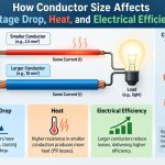
Long conductors have more resistance than short conductors of the same size. This produces voltage drop and additional heat along the run. The issue is more pronounced on heavily loaded circuits and on low-voltage systems where a small voltage loss is proportionally significant.
Motor loads can complicate the picture. Reduced voltage may cause some motors to draw more current or run less efficiently under load, adding stress to both the motor and the supply conductors. Proper design considers run length as well as breaker rating.
🔄 Harmonics can overload the neutral
Nonlinear loads, including many electronic power supplies, LED drivers, and variable-speed equipment, draw current in pulses rather than smooth sine waves. This can create harmonic currents.
In some multi-phase, shared-neutral arrangements, certain harmonic components can add in the neutral rather than cancel. The phase conductors may appear reasonably loaded while the neutral becomes unexpectedly hot. This requires competent load assessment, particularly in offices, data spaces, and facilities with extensive electronic loads.
⚖️ Unbalanced loads can heat one path more than expected
Multi-phase and multiwire systems rely on correct load distribution and conductor arrangements. When loads are heavily unbalanced, one phase or neutral path can carry more current than a quick glance at total connected load suggests.
Measurements should be taken on each conductor under representative operating conditions. Total panel demand does not reveal a single overloaded phase, an overloaded neutral, or a poor termination on one branch.
🌀 Skin effect is usually not the household explanation
At alternating-current frequencies, current tends to concentrate somewhat toward the outer region of a conductor. This is called skin effect. It becomes increasingly relevant at higher frequencies and for larger conductors.
At ordinary power frequencies in typical small building wiring, loose connections, undersizing, bundling, ambient heat, and overload are usually far more plausible explanations for overheating. Knowing this prevents an exotic theory from distracting attention from common faults.
🏭 Industrial loads introduce different duty cycles
Welders, compressors, pumps, cranes, ovens, and machinery can impose cycling loads, frequent starts, high inrush currents, or elevated ambient temperatures. Their conductors and protective devices are selected using duty-specific methods rather than a simple “load current equals breaker rating” rule.
A circuit may survive occasional operation but overheat during repeated cycles because it never has enough time to cool. Duty cycle, conductor insulation class, enclosure temperature, and installation method all affect the result.
🔋 DC systems have their own overheating patterns
Direct-current circuits still obey resistive heating principles, but sustained DC arcs can be harder to extinguish because current does not naturally pass through zero as it does in AC systems. Loose connections in battery, solar, vehicle, and telecom systems deserve careful attention.
DC overcurrent protection must be correctly rated for voltage, interrupting capability, and application. An AC-rated device is not automatically suitable for a DC circuit, even when its current rating appears similar.
🧯 Insulation damage is both a symptom and a cause
Discoloured, brittle, cracked, melted, or hardened insulation often indicates exposure to excessive temperature. Once insulation has degraded, its electrical and mechanical properties may be compromised.
Damaged insulation can then allow leakage current, faults to earth, conductor contact, or further heating. Simply restoring power after a breaker reset does not establish that the cable remains serviceable; the affected section may require inspection and replacement.
👃 Warning signs worth taking seriously
Not every warm surface is abnormal. Some equipment is designed to operate warm, and a loaded conductor will naturally be warmer than its surroundings. What matters is unexpected heat, change over time, localized hot spots, or heat accompanied by other warning signs.
- A plug, outlet, switch, or panel cover that is unusually hot to touch
- A persistent burning, fishy, or hot-plastic odor
- Flickering lights, intermittent equipment operation, or crackling sounds
- Brown marks, melted plastic, discolouration, or softened insulation
- A breaker that trips repeatedly, or a circuit that suddenly behaves differently
Do not open energized equipment to investigate these symptoms. If there is smoke, sparking, or active heating, de-energize the circuit if it can be done safely and seek qualified assistance.
📷 Thermal imaging finds patterns, not final answers
Infrared thermal imaging can reveal a hot lug, overloaded phase, warm cable bundle, or abnormal connection without direct contact. It is especially useful when equipment is operating under normal load.
However, an infrared image needs interpretation. Surface emissivity, reflections, load level, enclosure airflow, and camera settings affect what appears on screen. A hot spot identifies a condition to investigate; it does not by itself prove the precise root cause.
📊 Measure current under real operating conditions
A clamp meter can measure current without disconnecting a conductor, helping a qualified person compare actual load with circuit design and protective-device ratings. Measurements should be made when the load is genuinely active, not only during idle periods.
For complex systems, useful checks may include phase balance, neutral current, voltage drop, power factor, harmonic content, and peak demand. The right measurement depends on the circuit; one current reading cannot diagnose every thermal problem.
🧰 Inspection must include the whole current path
It is tempting to inspect only the breaker panel. Yet overheating can occur at the appliance plug, receptacle, junction box, isolator, cable gland, motor terminal, or hidden splice.
A systematic investigation follows the current path from source to load. It checks conductor size and condition, termination compatibility, mechanical support, environmental exposure, loading pattern, protective-device selection, and evidence of previous heat damage.
🚫 Common responses that make the hazard worse
Several quick fixes can conceal the symptom while increasing risk:
- Installing a larger breaker to stop nuisance trips
- Continuing to use a hot extension lead or multi-plug adapter
- Retightening an energized connection without proper procedures
- Replacing a damaged plug while ignoring a heat-damaged receptacle
- Assuming a cable is safe because power still reaches the load
These actions fail because they do not identify whether the problem is overload, resistance, poor heat dissipation, equipment failure, or a combination of conditions.
🛠️ Correct the cause, not just the temperature
The appropriate remedy depends on the fault. It may involve reducing continuous load, installing a correctly designed dedicated circuit, replacing damaged cable, remaking a termination, improving cable routing, separating bundled conductors, or changing equipment that is drawing abnormal current.
Protection changes must be part of a coordinated design decision. Cable insulation temperature rating, conductor ampacity, termination temperature limits, installation rules, prospective fault current, and breaker characteristics all need to remain compatible.
🧑🔧 When to call a qualified electrician or engineer
Homeowners and operators can observe symptoms, stop using suspect equipment, and avoid overloading adapters. They should not attempt energized panel work, concealed-wiring repairs, or modifications to protective devices.
Bring in a qualified electrician for hot outlets, repeated tripping, damaged insulation, unexplained odor, panel heat, or any suspected loose connection. Larger facilities may need an electrical engineer or experienced maintenance professional to review load studies, coordination, harmonics, and distribution design.
📋 A practical prevention routine
Preventive action is usually simpler than fault recovery. Keep loads within circuit design limits, use approved equipment, avoid permanent reliance on extension leads, and ensure added insulation or renovations do not bury or damage wiring.
For commercial and industrial installations, planned inspection can include torque verification where permitted by procedures, thermal surveys under meaningful load, cleaning and environmental checks, and review of circuits after equipment changes. Documentation helps reveal whether temperatures or load levels are drifting over time.
🧠 The core principle: current protection has limits
A breaker provides essential protection against overcurrent and severe faults, but it cannot guarantee that every component remains cool. A cable system is safe only when conductor size, termination quality, heat dissipation, load characteristics, and protective devices work together.
The most useful mental model is simple: the breaker sees circuit current; the cable experiences both current and its local environment. A high-resistance joint, trapped heat, unsuitable conductor, or damaged connection can therefore overheat before the breaker has a reason to trip.
When electrical heat appears where it is not expected, treat it as diagnostic information rather than an inconvenience. Find the source, assess the complete current path, and restore the installation to a condition that is safe for its actual load.
An untripped breaker does not prove that every cable and connection is operating safely. Recognizing that limit helps prevent small thermal defects from becoming major failures. ⚡🔧🔥