
A workshop compressor starts slowly at the far end of a building. A garden pump runs but its motor casing feels unusually hot. A bank of LED fixtures looks slightly dimmer at the end of a long corridor. The equipment may be functioning, but the conductors feeding it may be part of the problem.
Wire is often treated as a simple connection between a source and a load. In reality, every conductor has resistance, and resistance changes what arrives at the load. A circuit can lose voltage, waste energy as heat, and perform poorly even when its breaker has not tripped.
Conductor size is one of the main design choices that controls these effects. Selecting it well requires more than choosing a wire that can survive the expected current. Distance, installation conditions, load behavior, voltage level, and local electrical rules all matter.
Understanding the relationship gives students a useful foundation and helps working professionals recognize when a larger conductor is not extravagance, but sound electrical engineering.
⚡ The Three Effects to Connect
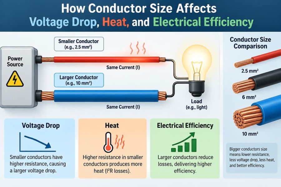
Conductor size affects three closely related outcomes: voltage drop, heating, and efficiency. Voltage drop is the reduction in voltage between the supply and the load. Heating is the thermal energy produced as current passes through conductor resistance.
Efficiency describes how much input power reaches the useful load rather than becoming loss in the wiring. These are not separate problems. The same resistance that causes a voltage drop also produces heat and consumes real power.
🧱 A Conductor Is Not an Ideal Wire
Basic circuit diagrams commonly show connecting wires with no resistance. That simplification is useful for early analysis, but physical conductors always oppose current to some degree.
Resistance depends on material, length, cross-sectional area, and temperature. Terminations, joints, switches, and connectors add resistance too. In a short low-current circuit these effects can be minor; in a long feeder or high-current branch circuit, they can shape equipment performance.
📏 What “Conductor Size” Actually Means
Conductor size refers to the cross-sectional area of its conductive metal, not the outside diameter including insulation. A larger copper or aluminum cross-section offers more parallel paths for charge carriers and therefore lower resistance.
Different systems express size differently. American Wire Gauge (AWG) uses a reverse numbering system: a smaller AWG number means a larger conductor. Many other systems use square millimetres, where the relationship is more direct: more mm² means more metal area.
🛣️ The Pipe Analogy, Used Carefully
A water-pipe analogy is helpful. A larger pipe creates less restriction to a given flow, much as a larger conductor creates less resistance to a given current. A long pipe adds friction; a long wire adds resistance.
The analogy has limits. Electrical current does not behave exactly like flowing water, and alternating-current circuits introduce impedance effects. Still, it correctly captures the central design idea: longer paths need more conductive area to keep losses controlled.
📐 Resistance Falls as Area Increases
For a uniform conductor, resistance can be represented by R = ρL/A. Here, ρ is the material resistivity, L is conductor length, and A is cross-sectional area.
This relationship explains two practical facts. Doubling length doubles resistance, while increasing area reduces resistance. The relationship is inverse, so a meaningful increase in conductor area can substantially reduce loss on a long run.
↔️ Circuit Length Usually Means Out and Back
Current must complete a path. In a simple single-phase circuit, it travels outward on one conductor and returns on another, so voltage-drop calculations normally use the total loop length.
For example, a load located 50 m from its source may have roughly 100 m of current path through the outgoing and return conductors. Forgetting the return path is a common reason voltage-drop estimates are far too optimistic.
🔻 Voltage Drop in Plain Language
Voltage drop is commonly estimated from Vdrop = I × R. If a conductor loop has resistance and load current flows, part of the source voltage is used across that conductor resistance.
Suppose a hypothetical 24 V load draws 5 A and the wiring loop resistance is 0.4 Ω. The wiring drop is 2 V, leaving approximately 22 V at the load. Whether that is acceptable depends on the equipment’s allowable input-voltage range.
🔥 Why Resistive Heating Rises So Quickly
Conductor heat loss follows P loss = I²R. The squared-current term is especially significant. If current doubles while resistance stays unchanged, conductor heating becomes four times greater.
That is why a conductor that seems acceptable for a modest load can become unsuitable after equipment is upgraded. It also explains why high-current circuits, such as battery connections, electric heating equipment, and low-voltage distribution, demand careful conductor selection.
💡 Power Loss Is Energy You Paid For
The watts dissipated in a conductor do no useful work at the intended load. They become heat in the cable, terminals, and surrounding installation. Over time, this loss contributes to energy use and may raise temperatures in enclosed pathways.
At a given current, a larger conductor lowers resistance and therefore lowers I²R loss. The value of those saved watts depends on operating hours, loading pattern, and energy cost, but the physical principle is constant.
📊 Voltage Drop and Efficiency Are Related but Different
A circuit can have a voltage drop that disrupts a sensitive load even when wire loss is not a large fraction of the total system power. Conversely, a high-current circuit can waste considerable power while a robust load continues operating acceptably.
Voltage drop focuses on the voltage available at the load. Efficiency focuses on input versus useful delivered power. Good design checks both rather than treating one as a substitute for the other.
🔌 Why Low-Voltage Systems Need Extra Attention
A 2 V drop has very different meaning in different systems. On a 230 V supply, it is a relatively small fraction. On a 12 V system, it is a large share of the available voltage.
This is why conductor sizing is especially consequential in vehicle wiring, solar battery systems, telecommunications power, landscape lighting, and control circuits. Low voltage often requires large conductors because the design must preserve a much larger percentage of the source voltage.
🏭 High Voltage Helps Move Power Efficiently
For a given power demand, higher voltage allows lower current because approximately P = V × I. Lower current reduces conductor heating dramatically because heating depends on current squared.
This is a central reason electrical systems use transformers and higher distribution voltages for moving power over distance. It does not eliminate conductor resistance, and higher voltage creates different insulation and safety requirements, but it reduces current-related loss.
🧰 Ampacity Is Not a Voltage-Drop Calculation
Ampacity is the current a conductor can carry under stated installation conditions without exceeding its permitted temperature limit. It is primarily a thermal safety rating based on conductor insulation, ambient temperature, bundling, enclosure conditions, and applicable rules.
A conductor can meet ampacity requirements and still produce excessive voltage drop on a long route. Conversely, increasing wire size for voltage-drop performance does not remove the need to select overcurrent protection and insulation ratings correctly.
🌡️ Temperature Changes Resistance
For common metallic conductors, resistance rises as temperature rises. Copper and aluminum therefore have higher resistance when hot than when measured at a cooler reference temperature.
This creates a feedback effect: current produces heat, heat increases resistance, and increased resistance produces more heat. Design methods account for normal operating conditions, but unusual ambient temperatures, crowded cable pathways, or poor terminations can push a real installation beyond simple expectations.
🧲 Copper and Aluminum Do Not Behave Identically
Copper has lower resistivity than aluminum, so an aluminum conductor generally needs more cross-sectional area to achieve comparable resistance. Aluminum is lighter and can be a practical choice for large feeders and distribution conductors when properly designed.
The choice is not simply “better” versus “worse.” Terminations must be listed for the conductor material, preparation and torque requirements matter, and installation methods must follow the governing electrical code and manufacturer instructions.
〰️ AC Adds Impedance to the Picture
In direct-current circuits, resistance is usually the dominant conductor quantity. In alternating-current circuits, impedance also includes inductive and capacitive effects. The exact voltage-drop calculation can depend on conductor arrangement, power factor, raceway material, and system configuration.
At ordinary building frequencies and common conductor sizes, resistance remains highly relevant. For long runs, large conductors, or specialized systems, simplified DC-style estimates may not be accurate enough for final design.
🌀 Skin Effect Matters at Higher Frequencies
With AC, current tends to concentrate closer to a conductor’s surface as frequency increases. This is called skin effect and increases effective AC resistance relative to DC resistance.
At standard mains frequency in many everyday installations, skin effect is often modest for typical branch-circuit conductors. It becomes much more important in large conductors, high-frequency power electronics, radio-frequency systems, and certain busbar applications.
⚙️ Motors React Strongly to Low Voltage
Many motors draw a high inrush current while starting. If feeder impedance is significant, this starting current can cause a temporary voltage sag at the motor terminals. The motor may start slowly, fail to accelerate properly, or impose stress on related equipment.
Running undervoltage can also affect torque and temperature, depending on motor type and load. A conductor choice should consider not only steady-state current but also starting conditions, duty cycle, and the voltage tolerance specified for the equipment.
💻 Electronics Have Different Failure Modes
Some electronic devices use regulated power supplies that tolerate a range of input voltages. Others may shut down, reset, flicker, report faults, or operate unreliably when the source at their terminals falls too low.
Control systems are particularly vulnerable when a long shared conductor causes voltage dips as solenoids, contactors, or motors energize. Separating sensitive control wiring, using suitable distribution arrangements, or providing local regulated power can be more effective than merely increasing one cable size.
🔋 DC Loads Show the Problem Clearly
Consider a hypothetical 12 V pump drawing 15 A through a long cable run. Even a small resistance can consume enough voltage that the pump receives substantially less than its nominal supply. The resulting current and performance may not behave as a simple fixed-resistance calculation predicts.
Battery systems add another complication: battery voltage itself changes with state of charge, load, temperature, and battery chemistry. Voltage-drop design should preserve enough terminal voltage during realistic operating conditions, not only under ideal open-circuit battery voltage.
🧮 A Simple Sizing Workflow
A disciplined process avoids selecting cable by habit. Start by identifying the actual circuit requirements, then calculate or verify both safety and performance limits.
- Determine load current, voltage, duty cycle, and load type.
- Measure or estimate the one-way route length and establish the full current path.
- Select a preliminary conductor based on ampacity and installation conditions.
- Calculate voltage drop using appropriate resistance or impedance data.
- Increase conductor size, change voltage, shorten the route, or revise the architecture if needed.
- Verify protection, termination compatibility, fault performance, and applicable code requirements.
📋 What a Useful Design Calculation Needs
Good calculations depend on good inputs. A nominal breaker rating alone is not enough, because the real load may be intermittent, continuous, nonlinear, motor-driven, or expected to expand later.
| Input | Why it affects the result |
|---|---|
| Route length | Longer conductors have more resistance and impedance. |
| Expected current | It sets voltage drop and has a squared effect on heating loss. |
| Conductor material and size | They determine resistance and allowable current under conditions. |
| System voltage and phase | They affect current level and calculation method. |
| Installation environment | Ambient temperature and grouping influence ampacity. |
| Load characteristics | Motor starting, power factor, and sensitivity may govern design. |
📍 Locate the Source and Load Precisely
Voltage drop occurs from the actual point where power is regulated or supplied to the terminals where the load consumes it. In a building, that might mean from a distribution panel to a machine disconnect, then through a branch circuit to the equipment.
Ignoring intermediate connections can hide a problem. A circuit may have correctly sized feeder conductors but still deliver poor voltage because of undersized flexible cord, corroded connectors, or a long final branch circuit.
🔩 Terminations Can Defeat a Large Cable
A large conductor does not guarantee a low-resistance connection. Loose lugs, contaminated contact surfaces, incorrect crimping, unsuitable terminals, and mechanical damage can create localized resistance.
Unlike a properly sized cable, a poor joint concentrates heat in a very small area. Signs can include discoloration, insulation damage, a hot connection, or intermittent operation. Inspection and testing must be performed safely by qualified personnel under the applicable procedures.
🧯 Heat Depends on Where the Cable Lives
A conductor installed in free air can reject heat more effectively than one enclosed in insulation, a crowded raceway, or a hot equipment compartment. Multiple loaded circuits placed together can warm each other, reducing their ability to carry current safely.
These conditions are addressed through ampacity tables and adjustment factors in local rules. They also explain why a conductor that works well on an open test bench may be unsuitable inside a tightly packed installation.
🚫 Common Sizing Mistakes
Several shortcuts repeatedly lead to disappointing or unsafe results:
- Selecting wire from breaker size alone and ignoring route length.
- Using one-way distance where a loop path is required.
- Assuming a larger breaker solves equipment undervoltage.
- Ignoring motor starting current or voltage-sensitive electronics.
- Using conductor area without checking terminal and insulation ratings.
- Applying a DC resistance estimate to an AC system where impedance matters.
- Oversizing conductors without confirming that lugs, glands, bends, and raceways can accommodate them.
A larger breaker does not improve voltage at a load. It can instead expose an undersized conductor to damaging current if protection is no longer coordinated with conductor ampacity.
🛠️ Practical Ways to Reduce Voltage Drop
Increasing conductor area is often the direct solution, but it is not the only option. The best choice depends on project constraints, equipment requirements, and whether the circuit is new or existing.
- Shorten the route or move distribution closer to the load.
- Use a higher distribution voltage where the system can safely support it.
- Reduce current by changing equipment or distribution architecture.
- Use parallel conductors only when permitted and properly engineered.
- Improve connectors and replace degraded terminations.
- Provide local power conversion or regulation for sensitive low-voltage loads.
💰 The Trade-Off: Copper Cost Versus Operating Cost
Larger conductors usually cost more, take up more space, weigh more, and can be harder to pull and terminate. Those practical costs matter, especially in retrofit work or congested pathways.
However, smaller conductors create more lifetime loss at the same current. For heavily loaded circuits that operate many hours, the additional material cost may be balanced by lower energy loss and better equipment performance. A sound evaluation considers installation cost, operating profile, reliability, and future capacity rather than initial material price alone.
🏗️ Allowing for Future Load Growth
Feeders and conduits are difficult to replace after walls are closed or equipment is operating. Where reasonable load growth is expected, designing only for today’s minimum can create an expensive bottleneck later.
Future planning does not mean arbitrarily oversizing every circuit. It means documenting assumptions and considering realistic additions: another motor, longer operating hours, battery expansion, or a change from lighting loads to charging loads.
🧪 Field Checks That Reveal Problems
A voltage reading at the source is not enough. Compare source voltage with voltage measured at the load terminals while the load operates under representative conditions. A no-load reading can look normal even though the conductor drop becomes significant under current.
Other useful evidence can include current measurement, thermal inspection, visual examination of connections, and review of load operating history. Measurements should be taken with correctly rated instruments and appropriate electrical safety practices.
📚 Codes, Standards, and Engineering Judgment
Electrical codes establish minimum safety requirements, but their details vary by jurisdiction and installation type. They address conductor ampacity, overcurrent protection, grounding, termination methods, derating, and many other conditions beyond voltage drop.
Design recommendations for voltage drop may differ by application or standard. They should be treated as design guidance, not as permission to ignore mandatory local requirements. Complex, high-energy, industrial, or safety-critical systems deserve review by a qualified electrical professional.
🎯 The Core Principle to Remember
Conductor size controls resistance; resistance controls voltage drop and resistive loss; current magnifies heating through the I²R relationship. Long routes and low-voltage, high-current loads make these effects especially visible.
The best conductor is not merely the smallest one that avoids overheating. It is the size that safely fits the installation, delivers acceptable voltage at the load, limits losses appropriately, works with the required terminals and protection, and supports the system’s real operating conditions.
Choose conductor size as a system decision: account for current, distance, temperature, equipment behavior, and the voltage the load must actually receive. That approach turns a wire selection into reliable electrical design. 🔌⚡🛠️