
A workshop compressor starts with a deep hum, the lights dim for a moment, and then everything settles into a normal rhythm. A similar thing happens when an air-conditioner compressor, a large pump, or even a household refrigerator begins running.
That brief electrical surge is not usually a fault. It is a predictable part of how most motors convert electrical energy into motion. But it can trip breakers, stress cables, disturb a weak supply, and determine whether a machine starts reliably under load.
For students, startup current connects circuit theory to a physical machine. For working professionals, it affects feeder sizing, protective-device coordination, generator selection, voltage-drop calculations, and troubleshooting.
The central idea is simple but powerful: a motor at rest has no back electromotive force to oppose the supply voltage. Understanding what that means explains why its first few moments demand so much current.
⚙️ The Short Answer: No Back EMF at Standstill
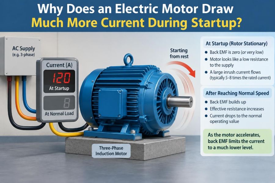
When a motor is stationary, its rotating parts produce essentially zero back EMF. Back EMF, or counter-electromotive force, is a voltage generated inside a motor that opposes the applied supply voltage.
With little opposing voltage at the instant of energization, the winding current is limited mainly by winding resistance and inductive reactance. Those impedances are deliberately low in a motor designed to operate efficiently, so the initial current can be several times larger than the normal running current.
🔄 A Motor Is Also an Electromagnetic Generator
An operating motor is not merely a device that consumes electrical power. As its rotor moves through magnetic fields, it also generates an internal voltage.
In a DC motor, conductors cut magnetic flux as the armature rotates. In an induction motor, the changing relationship between the rotating stator field and the rotor induces rotor currents, whose magnetic effects are reflected back to the stator. The details differ, but the useful result is alike: motion creates an electrical opposition to the supply.
🧲 What Back EMF Actually Does
Back EMF is not an extra loss added to the circuit. It is the motor’s natural electrical response to rotation. It reduces the voltage left to drive current through the winding impedance.
A simplified DC-motor relationship is:
I = (V - Eb) / R
Here, V is supply voltage, Eb is back EMF, and R represents armature resistance. At zero speed, Eb is near zero, so current is potentially very large. As speed rises, back EMF rises and current falls.
🚦 The First Instant After Switching On
At startup, inertia keeps the rotor still. The electrical system, however, applies full voltage almost immediately. Current begins building in the windings and creates magnetic flux.
That flux produces torque, but torque cannot make a massive rotor, pump impeller, belt system, or compressor jump instantly to full speed. During acceleration, the motor remains below its normal back-EMF-producing speed, so it continues drawing elevated current.
📉 Why Low Winding Resistance Matters
Motor windings use thick conductors and relatively few turns compared with many other coils. This keeps copper losses low during normal operation and allows the motor to carry its rated current efficiently.
The trade-off is that winding resistance alone is a poor current limiter. A small motor may have only a fraction of an ohm of DC winding resistance, while larger machines can have even lower values. Applying rated voltage to that resistance at standstill would suggest a very large current if other effects were ignored.
🌊 Inductance Limits Current, But Not Enough
Windings are inductive, so their current cannot rise infinitely fast. Inductive reactance provides some opposition in AC circuits, and magnetic behavior is more complex than a simple resistor model.
Still, inductance does not eliminate inrush. Designers need low effective impedance to produce useful torque and efficient full-speed operation. At startup, that same low impedance permits a high current until rotation changes the electrical conditions.
🌀 Induction Motors: The Most Common Case
Most industrial AC motors are squirrel-cage induction motors. Their stators create a rotating magnetic field. At standstill, that field sweeps past the rotor conductors at the maximum possible relative speed.
The induced rotor current is therefore high, and the stator draws a corresponding high current from the supply. In motor terminology, the rotor has a slip of 1 at standstill: it is not moving at all while the stator field rotates.
📍 Slip Explains the Changing Current
Slip is the difference between synchronous speed, the speed of the stator’s rotating field, and actual rotor speed. As the induction motor accelerates, slip decreases.
Lower slip changes rotor frequency and the effective impedance seen by the motor. The motor transitions from a standstill condition with high current toward its ordinary operating point, where it draws the current needed for its mechanical load and losses.
🏎️ Starting Torque Must Overcome Inertia
Current is not drawn simply because the motor “wants power.” It is drawn because electromagnetic torque is needed to accelerate the rotating system and overcome opposing torque.
The required torque may include rotor inertia, bearings, a fan, a conveyor, a pump, a loaded gearbox, or a compressor beginning against pressure. More difficult starting conditions often keep the motor at low speed longer, extending the period of high current.
📦 Load Type Changes the Starting Experience
Not every driven machine behaves alike. A freely spinning fan may accelerate rapidly, whereas a loaded crusher or positive-displacement pump can demand substantial torque from the first turn.
| Driven load | Typical startup behavior | Design concern |
|---|---|---|
| Fan or centrifugal pump | Torque usually rises strongly with speed | Often starts relatively easily, though inertia can still matter |
| Conveyor | May begin with material already on the belt | Breakaway torque and long acceleration |
| Compressor | May start against pressure difference | High starting torque and voltage sensitivity |
| Positive-displacement pump | Can require near-full torque at low speed | Motor and starter must handle demanding starts |
These are general patterns, not substitutes for the driven-equipment data supplied by the manufacturer.
🔢 Locked-Rotor Current Versus Inrush Current
Locked-rotor current is the current a motor draws when rated voltage is applied while its rotor cannot turn. It represents a severe standstill condition and is often used in motor ratings and protection studies.
Inrush current is a broader practical term for the elevated current seen when equipment is energized. For a motor that starts normally, the initial current may resemble locked-rotor current briefly, then decay as speed builds. The exact waveform and duration depend on motor design, supply stiffness, and load.
📏 Rated Current Is Not Startup Current
Nameplate full-load current describes an expected operating condition at rated voltage, frequency, and load. It should not be treated as the highest current the motor will ever draw.
Many across-the-line induction motors draw several times their full-load current during starting. The actual ratio varies with design, size, efficiency class, rotor construction, and voltage, so a generic multiplier is useful only as an early estimate. Use manufacturer data for equipment selection.
⚡ Voltage Drop Can Create a Startup Problem
High starting current flowing through source impedance, transformers, cables, contacts, and connections causes voltage drop. The motor terminals then receive less voltage precisely when the motor needs torque to accelerate.
For many induction motors, available torque changes approximately with the square of terminal voltage. A modest voltage reduction can therefore cause a much larger reduction in starting torque. The motor may accelerate slowly, remain near standstill, or fail to start altogether.
🔁 A Weak Supply Can Become a Vicious Cycle
Suppose a motor begins starting at the end of a long feeder. Its current produces substantial feeder voltage drop. Reduced motor voltage lowers torque, so acceleration slows.
Because it stays at high slip for longer, elevated current persists. This does not mean current rises without limit; the motor’s electrical characteristics still constrain it. But the prolonged start produces extra heating and can trigger protective devices or pull down nearby loads.
🔥 Heating Depends on Both Current and Time
Copper loss is proportional to I²R. A high current over a short, successful start may be acceptable because the motor has thermal mass and startup is brief.
A stalled or repeated-start condition is different. High current remains while little useful mechanical output is produced, and winding temperature can rise quickly. Thermal overload protection is intended to respond to damaging overloads, but it cannot excuse poor starting design or repeated unsuccessful attempts.
🛑 Stall Is Not a Normal Long-Term Condition
A stalled motor has energized windings but no meaningful rotor motion. Its back EMF is absent or very low, and its current can remain close to the locked-rotor value.
Causes include a jammed machine, seized bearings, an overloaded conveyor, a blocked pump, a failed capacitor in some single-phase motors, or inadequate supply voltage. If a motor hums without reaching speed, de-energize it promptly and investigate rather than allowing it to overheat.
🧯 Why Breakers Do Not Always Trip Instantly
Motor circuits need protection from short circuits, ground faults, sustained overload, and overheating. These conditions are different, so protection is usually coordinated rather than handled by one device alone.
Fuses or circuit breakers may be selected to tolerate the brief starting surge without opening, while overload relays or electronic motor protection respond to excessive current lasting too long. Settings must follow applicable electrical rules, local practice, and manufacturer instructions; simply installing a larger breaker to stop nuisance trips can remove essential protection.
🔌 Direct-On-Line Starting
Direct-on-line, also called across-the-line starting, connects the motor directly to the full supply voltage through a starter or contactor. It is simple, inexpensive, and provides the motor’s normal starting torque capability.
Its drawback is the high line current and associated voltage dip. It is often suitable where the supply is stiff and the motor is modest relative to the system, but it may be unsuitable for large motors, weak networks, or loads that cannot tolerate voltage disturbance.
📉 Star-Delta Starting and Its Trade-Off
A star-delta starter initially connects a suitable three-phase motor in star, then changes it to delta for normal operation. The initial phase voltage is lower than with direct delta connection.
This reduces line current, but it also reduces starting torque substantially. Star-delta starting is therefore not a universal cure. A load that needs high breakaway torque may fail to accelerate before the transition, producing a rough or unsuccessful start.
🧩 Autotransformer and Primary-Resistor Starters
Reduced-voltage starters can lower the motor terminal voltage for the initial start and then restore full voltage. Autotransformer starters use transformer action; resistor or reactor starters introduce impedance in the supply path.
They can limit supply disturbance, but reduced voltage also reduces available torque. The correct choice depends on the motor, load torque curve, permitted voltage dip, starting frequency, and the behavior of the broader electrical system.
🌡️ Soft Starters Control Voltage Ramp
Electronic soft starters commonly use thyristors to gradually increase the effective voltage applied to an AC motor. They can reduce mechanical shock, limit current, and provide adjustable acceleration behavior.
They do not create full torque at arbitrarily low current. If the current limit is set too low for the load, the motor may take too long to reach speed and heat excessively. Soft starters are especially useful where smooth starts matter, but their settings require commissioning rather than guesswork.
🎛️ Variable-Frequency Drives Change the Strategy
A variable-frequency drive, or VFD, starts an AC motor by controlling both frequency and voltage. By beginning at low frequency and maintaining an appropriate voltage-to-frequency relationship, it can develop useful torque without applying line-frequency locked-rotor conditions directly to the motor.
VFDs often offer controlled acceleration, process control, and lower line inrush. They also introduce harmonics, require attention to cable length and motor insulation in some applications, and may need specific measures for bearing currents, cooling at low speed, or electromagnetic compatibility.
🏠 Single-Phase Motors Need a Rotating Start Field
A basic single-phase supply produces an alternating field, not the naturally rotating field available in a three-phase motor. Single-phase motors therefore use arrangements such as start windings, capacitors, shaded poles, or electronic controls to establish starting torque.
A capacitor-start motor can draw substantial current during startup. If its start capacitor, centrifugal switch, relay, or start winding fails, the motor may hum and stall. Continuing to energize it in that state is risky because high current persists without cooling airflow or acceleration.
🔋 DC Motors Follow the Same Core Principle
In a brushed DC motor, back EMF is closely related to speed. At rest, there is no rotational back EMF, so armature current is limited mainly by armature resistance and any controller-imposed limit.
This is why DC drives use current control. High starting current produces high torque, but uncontrolled current can damage windings, commutators, brushes, controllers, or batteries. Modern electronic drives manage this trade-off deliberately.
🔍 Measuring Startup Current Correctly
An ordinary multimeter usually cannot capture a fast motor-start transient meaningfully. Use an inrush-capable clamp meter, power-quality analyzer, current probe with an oscilloscope, or drive data logger appropriate to the waveform and expected current.
Measure all phases on a three-phase motor. A significant imbalance can indicate a supply issue, poor connection, winding problem, contactor fault, or developing mechanical problem. Interpret measurements alongside terminal voltage, acceleration time, load condition, and ambient temperature.
🧪 A Practical Troubleshooting Sequence
When a motor trips during startup, begin with safe isolation and the equipment documentation. Do not assume the motor is defective merely because the breaker opened.
- Verify the motor rating, supply voltage, frequency, connection arrangement, and starter configuration.
- Check whether the driven equipment can rotate freely and whether it is starting under an unusual load.
- Measure voltage at the motor terminals during starting, not only at the distribution panel.
- Measure startup current and acceleration time on each phase where safe and appropriate.
- Inspect terminals, contactors, fuses, cable condition, and protective-device settings for damage or loose connections.
- Compare observations with motor and starter documentation before changing settings or hardware.
Live testing presents arc-flash, shock, and rotating-equipment hazards. It should be performed only by qualified personnel using suitable procedures and protective equipment.
🧠 Common Misconceptions to Avoid
- “The motor draws the same current all the time.” Current changes with speed, load, voltage, and control method.
- “High startup current means the motor is inefficient.” A brief surge is normal for many motors; efficiency is evaluated under defined operating conditions.
- “A bigger breaker solves a startup trip.” It may conceal a stalled load, undersized feeder, wrong protection setting, or faulty starter.
- “A soft starter always solves the problem.” Reduced current also means reduced available torque.
- “The motor alone determines starting current.” The supply impedance, wiring, starter, and mechanical load all influence what happens.
📐 Designing for a Successful Start
A reliable design considers the motor and the system around it. Obtain locked-rotor current, torque-speed data where available, expected start time, starts per hour, and driven-load characteristics.
Then evaluate feeder voltage drop, transformer or generator capability, upstream protection, contactor duty, cable thermal limits, and the effect on other connected loads. A motor that starts well on a utility supply may behave very differently on a small generator or long temporary cable run.
🏭 Generator and Transformer Sizing Considerations
Transformers and generators must tolerate the motor’s starting demand without allowing unacceptable voltage depression. The question is not merely whether their continuous rating exceeds the motor’s running power.
Generator performance also depends on alternator reactance, engine response, excitation system behavior, and the sequence in which loads start. For facilities with multiple motors, staged starting or controlled starts may be preferable to starting everything at once.
🧰 Maintenance Can Reduce Startup Stress
Maintenance cannot remove the fundamental inrush associated with a conventional start, but it can prevent abnormal starts. Lubricated bearings, aligned couplings, clean ventilation paths, sound electrical connections, and correctly operating unloading mechanisms all help a motor reach speed promptly.
Trend data is valuable. A gradual increase in start time, current asymmetry, or voltage dip can reveal a developing mechanical or electrical issue before it becomes a no-start event.
🎯 The Core Principle to Remember
At standstill, a motor has not yet developed the motion-induced electrical opposition that normally limits its current. The supply therefore sees a low-impedance electromagnetic load, while the motor needs high electromagnetic torque to begin accelerating.
As speed rises, back EMF in DC machines or the changing slip condition in induction machines reduces the effective current demand toward its normal operating value. Starting methods do not repeal this physics; they manage the trade-off among current, torque, acceleration time, voltage drop, cost, and process requirements.
An electric motor draws much more current during startup because it has little or no back EMF at zero speed, and that current is the electrical mechanism that produces the torque needed to accelerate the load. Design the supply, protection, controls, and mechanical system around that brief but demanding condition. ⚡🔄🛠️