
A production line is running normally: motors turn, compressors cycle, conveyors move materials, and control panels show no alarms. Yet the facility’s electricity bill is higher than expected, transformers feel heavily loaded, and an expansion project appears to require larger cables than the real process power seems to justify.
One often-overlooked reason is power factor. It does not usually stop a motor from running, so it can remain invisible until it shows up as avoidable utility charges, voltage problems, overheated equipment, or limited electrical capacity.
For industrial sites, power factor is not merely an item on a monthly bill. It affects how efficiently the entire electrical distribution system delivers useful power from the utility service to motors, drives, welders, and other loads.
Understanding it helps engineers make better design choices and helps maintenance teams distinguish a genuine correction opportunity from a misleading meter reading.
⚡ The Useful Power Behind Industrial Work
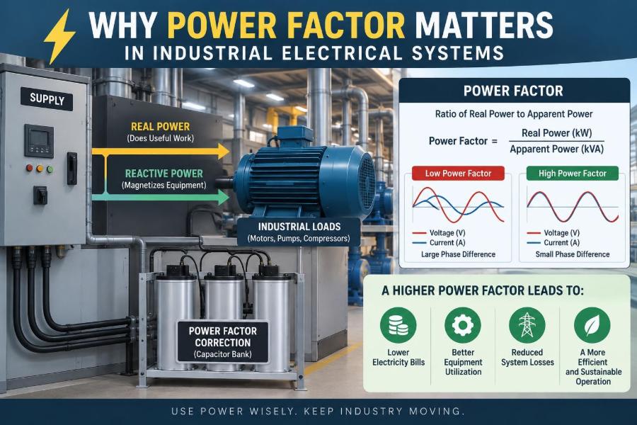
Real power, measured in kilowatts (kW), performs useful work. It produces torque in a motor, heat in a resistance heater, light in a luminaire, or output from a welding process.
If a 50 kW motor-driven machine is operating at its rated load, roughly that amount of real power is being converted into mechanical output and losses. Real power is the part of electrical power that a facility fundamentally needs to operate.
🔄 Why Alternating-Current Loads Need More Than kW
Industrial alternating-current systems must also supply energy that repeatedly moves into and out of magnetic or electric fields. Motors, transformers, reactors, and many types of lighting need magnetic fields; capacitive equipment stores energy in electric fields.
This field-building energy is called reactive power, measured in kilovolt-amperes reactive (kvar). It is necessary for many loads, but it does not directly create net mechanical work or process heat over a complete AC cycle.
Reactive power is not “wasted power” in the simplistic sense. An induction motor cannot produce its magnetic field without it. The issue is that excessive reactive power increases the current that conductors and equipment must carry.
📐 Apparent Power Connects the Two
Apparent power, measured in kilovolt-amperes (kVA), is the combined electrical demand seen by the supply. In a balanced three-phase system, it is related to line voltage and current:
kVA = √3 × line-to-line voltage × line current / 1000Real power, reactive power, and apparent power form the familiar power triangle. For sinusoidal conditions, their relationship is:
kVA² = kW² + kvar²A site can have the same kW demand at two different power factors. The lower-power-factor site will require more kVA and therefore more current to deliver the same useful kW.
📊 Defining Power Factor Clearly
Power factor is the ratio of real power to apparent power:
Power factor = kW / kVAIt has no unit and is commonly expressed as a decimal or percentage. A power factor of 0.90 means that 90% of apparent power corresponds to real power under the conditions being measured.
For sinusoidal voltage and current, power factor also equals the cosine of the phase angle between them. Current that lags voltage, typical of inductive loads, creates a lagging power factor. Capacitive loads can create a leading power factor.
🧠 A Simple Water-Flow Analogy
Imagine a pipe carrying water to turn a turbine. The useful flow that turns the turbine resembles kW. Water that surges back and forth in a side branch without producing turbine output resembles reactive power.
The main pipe must still be large enough for the total movement of water. Likewise, cables, switchgear, transformers, and generators must be sized for the current associated with kVA, not just the useful kW.
The analogy is imperfect because electrical current is not water, but it captures the operational point: unnecessary circulation consumes system capacity.
🏭 Why Industrial Plants Commonly Have Lagging Power Factor
Most industrial facilities contain many inductive loads. Their windings need magnetizing current, and the accumulated effect can make the site power factor lagging, especially when the plant is lightly loaded.
- Induction motors driving pumps, fans, conveyors, and compressors
- Transformers, particularly when energized with light secondary loading
- Induction furnaces and certain welding equipment
- Magnetic ballasts and older discharge-lighting systems
- Reactors used for current limiting or harmonic filtering
Variable-speed drives complicate the picture. A modern drive may improve displacement power factor at its input, but its nonlinear current can still reduce true power factor through distortion.
🛠️ Motors Are Often the Main Contributor
Induction motors are central to industrial work and central to many power-factor discussions. They draw magnetizing current whenever energized, even if the mechanical load is small.
A motor generally has better power factor nearer to its intended loading range than when it runs lightly loaded. An oversized motor driving a modest load may therefore contribute disproportionately to low facility power factor.
This does not mean a motor should always be selected at its minimum acceptable rating. Starting torque, overload duty, ambient conditions, service factor, and process reliability still matter. Good motor selection balances these requirements rather than optimizing one number alone.
📉 The Current Penalty of a Lower Power Factor
Consider a hypothetical 480 V three-phase load requiring 100 kW. At 0.80 power factor, it draws 125 kVA. At 0.95 power factor, it draws about 105 kVA.
Since voltage is unchanged, current follows kVA. Improving power factor in this example reduces supply current substantially while delivering the same 100 kW of process power.
| Condition | Real power | Power factor | Apparent power |
|---|---|---|---|
| Lower power factor | 100 kW | 0.80 | 125 kVA |
| Improved power factor | 100 kW | 0.95 | About 105 kVA |
The example assumes steady, balanced, sinusoidal conditions. Actual facilities must also account for harmonics, load variation, and measurement location.
🔥 Why Extra Current Raises Electrical Losses
Conductor and transformer winding losses are commonly described as I²R losses: current squared multiplied by resistance. When current rises, heating rises faster than current itself.
That added heat represents energy loss, but it also has practical consequences. It can increase equipment temperature, worsen voltage drop, and reduce margin during high-demand periods.
Power-factor correction does not eliminate the unavoidable losses inside a motor or the process energy required by a machine. It reduces upstream current associated with reactive demand when correction is properly applied.
🧯 Equipment Capacity Is Usually Rated in kVA or Amps
Transformers, generators, UPS systems, switchboards, circuit breakers, and cables have current or kVA limits. A transformer does not care whether current is associated with useful work or reactive magnetization; its windings still heat from total current.
This is why poor power factor can create a capacity bottleneck. A transformer may approach its kVA rating while the facility’s kW demand seems modest, leaving less room for additional production equipment.
Correcting power factor can sometimes release capacity. It should not be treated as permission to exceed thermal limits, interrupting ratings, or other design constraints.
📏 Voltage Drop Becomes More Noticeable
Every feeder has impedance: resistance and reactance. Higher current produces a larger voltage drop along that feeder, and reactive current affects the reactance-related portion of the drop.
At the load end, lower voltage can reduce motor starting performance, alter heater output, and make sensitive equipment less tolerant of disturbances. Long feeders to large motors are especially relevant.
Power-factor correction near a load can reduce feeder current and may improve voltage conditions. The result depends on conductor length, source strength, load behavior, and the location of the capacitor bank.
💸 How Utility Billing Can Reflect Power Factor
Utilities must provide generation, transmission, and distribution capacity in kVA, even though energy consumption is measured in kWh. For that reason, some industrial tariffs account for power factor, kVA demand, kvar demand, or a combination of these.
The exact billing method varies by utility agreement and jurisdiction. A facility may see a power-factor adjustment, a demand charge based on kVA, or no separate visible charge at all.
Before specifying correction equipment based on savings, review the actual tariff and interval data. Do not assume that a low reading on a panel meter automatically creates a direct financial penalty.
🧾 Demand Charges and Energy Charges Are Different
An energy charge reflects electricity consumed over time, typically kWh. A demand charge reflects the highest or measured average demand during defined intervals, often based on kW or kVA.
Improving power factor generally does not reduce the process kWh needed to move the same material or compress the same amount of air. Its financial effect is more often tied to kVA-related billing, avoided penalties, or deferred capacity upgrades.
This distinction prevents exaggerated savings claims. If a project promises dramatic kWh reduction solely from capacitor installation, the assumptions deserve careful examination.
🧭 Where Power Factor Should Be Measured
Power factor is location-dependent. A reading at the utility revenue meter includes the behavior of the whole facility and its distribution system. A reading at a motor starter describes only that local load.
For billing analysis, meter-level data matters most. For troubleshooting, measurements at main switchgear, distribution boards, feeders, and individual large loads help identify where reactive demand originates.
Time also matters. A single spot reading during normal production may miss low-load shifts, equipment starts, seasonal changes, or capacitor switching events.
🧮 Displacement Power Factor Versus True Power Factor
With clean sine waves, the phase-angle relationship tells most of the story. This is often called displacement power factor.
Modern industrial facilities also contain nonlinear loads such as rectifiers, variable-frequency drives, switched-mode power supplies, and LED drivers. These draw current in pulses and create harmonic currents, which can lower true power factor even when the fundamental current is nearly aligned with voltage.
A meter that reports only displacement power factor may therefore present an incomplete picture. For systems with significant electronics, use instruments that measure harmonics and true power factor.
🎵 Harmonics Change the Correction Problem
Harmonics are voltage or current components at frequencies that are integer multiples of the fundamental supply frequency. They can increase heating, stress capacitors, affect protection behavior, and interact with the system’s inductance and capacitance.
Adding ordinary capacitors to a harmonic-rich network can create or worsen resonance at particular frequencies. In severe cases, capacitor fuses operate repeatedly, capacitors overheat, or voltage distortion increases.
For this reason, correction in drive-heavy plants often requires a harmonic study or at least informed measurement. Detuned capacitor banks, harmonic filters, active filters, or drive-side mitigation may be appropriate depending on the system.
🧲 Capacitor Banks Supply Reactive Power Locally
Capacitors are the most common power-factor-correction device. They supply leading reactive power, offsetting part of the lagging reactive power demanded by inductive loads.
When a capacitor bank is connected near a load, some reactive current circulates between the capacitor and that load instead of travelling all the way from the upstream source. The source therefore supplies less reactive current.
Capacitors do not create real power. They reduce the reactive portion of the current that upstream equipment must provide.
📍 Choosing the Right Correction Location
Correction can be installed at several levels, and each approach has trade-offs.
- Individual correction: capacitors near a large, steady motor reduce current in its feeder but need careful switching and protection.
- Group correction: a bank serves several loads on a distribution board, offering a practical balance of benefit and flexibility.
- Central automatic correction: a stepped bank at the main distribution point follows changing facility demand and simplifies oversight.
The best location depends on load size, operating pattern, harmonic conditions, feeder constraints, and maintenance practices. There is no universal placement rule.
🔁 Why Automatic Banks Use Switching Steps
Plant reactive demand changes as motors start, stop, and vary in load. A fixed capacitor bank sized for peak operation can overcorrect when the plant is lightly loaded.
Automatic power-factor-correction banks use a controller and switched capacitor stages to follow demand. Switching may use contactors, thyristor-based devices, or other arrangements selected for the duty cycle.
Fast-changing loads require special attention. A conventional contactor-switched bank may not respond suitably to rapid load changes, and frequent switching can reduce component life.
🚫 Leading Power Factor Is Not a Free Upgrade
Overcompensation occurs when capacitors supply more reactive power than inductive loads require. The facility may then operate at leading power factor, especially overnight or during partial production.
Leading conditions can cause voltage rise and may conflict with utility requirements or generator operating limits. They can also signal that capacitor stages are too large, controls are poorly set, or fixed capacitors remain connected after motors stop.
The target is not the highest possible displayed number at every second. It is a stable, appropriate operating range consistent with the utility agreement and the electrical system’s behavior.
⚙️ Capacitors at Motor Terminals Need Care
Individual motor correction can be effective, but it must be designed with the motor starter and operating sequence in mind. A capacitor connected directly at motor terminals may remain energized with the motor under certain switching arrangements.
If the motor is reclosed before residual voltage decays, damaging transients can occur. Capacitor size must also be limited so that it does not create undesirable self-excitation or leading operation when the motor is lightly loaded.
Follow motor manufacturer guidance and applicable electrical codes. This is not a generic add-on task for untrained personnel.
🧪 Start With Load Data, Not a Capacitor Catalog
A sound project begins with measurement. Collect interval kW, kVA, kvar, power factor, voltage, current, and harmonic data over representative operating periods whenever possible.
Useful questions include:
- What are the facility’s peak and minimum operating loads?
- Is the problem a monthly billing issue, a capacity constraint, voltage drop, or all three?
- Which loads are steady, cyclic, nonlinear, or frequently switched?
- What is the transformer size, source impedance, and existing capacitor configuration?
- Are there signs of harmonic resonance or capacitor failures?
This evidence-based approach avoids installing correction that looks appropriate on paper but behaves poorly in service.
🧾 Estimating Required Capacitor Size
For a relatively stable sinusoidal load, required compensation can be estimated from real power and the initial and target power-factor angles:
Required kvar = kW × (tan φ₁ − tan φ₂)Here, φ₁ is the angle associated with present power factor and φ₂ is the angle associated with the desired power factor. The calculation provides a starting point, not a final design.
Real facilities need allowance for load diversity, capacitor tolerance, voltage variation, future changes, switching steps, and harmonics. A qualified engineer should verify equipment ratings, protection, discharge provisions, and resonance risk.
🧰 Alternatives Beyond Conventional Capacitors
Capacitor banks are not the only response. The best solution can be operational, equipment-based, or a combination.
- Replace consistently oversized or inefficient motors when lifecycle analysis supports it.
- Use correctly applied variable-speed drives to match motor output to process demand.
- Specify high-power-factor equipment during upgrades.
- Apply detuned banks or passive filters where harmonic conditions require them.
- Use active power-quality equipment when dynamic reactive compensation or harmonic mitigation is needed.
These options have different costs, losses, response times, and maintenance needs. A drive should not be installed solely to chase power factor if a simpler process or correction solution meets the real objective.
🔍 Common Mistake: Correcting a Number Without Understanding It
A frequent mistake is seeing a low power factor and immediately installing the largest available capacitor bank. This may mask the symptom while introducing leading operation or harmonic resonance.
Another mistake is relying on a facility-wide average. A good monthly average can hide a poor peak-demand interval, while a poor snapshot can occur during an unusual startup sequence and not represent normal operation.
Measurement context matters: identify whether the value is true or displacement power factor, whether it is instantaneous or averaged, and where the instrument is installed.
🧯 Common Mistake: Ignoring Protection and Maintenance
Capacitor systems require inspection and maintenance. Failed stages can quietly reduce correction, while swollen capacitors, damaged contactors, loose connections, and overheated reactors can create reliability risks.
Maintenance programs should examine switching cycles, fuse condition, ventilation, capacitor health indicators, controller settings, and signs of harmonic stress. Equipment must also be safely discharged before work; capacitors can retain hazardous voltage after isolation.
Arc-flash risk, lockout/tagout procedures, and local safety rules remain fully applicable. Power-factor equipment belongs in a managed electrical safety program.
🌡️ Ambient Conditions and Installation Details Matter
Capacitor life is sensitive to temperature, voltage stress, and harmonic current. A bank installed in a hot, poorly ventilated electrical room can age faster than expected even if its kvar rating appears adequate.
Enclosure ventilation, reactor heating, clearance, dust, and access for maintenance deserve attention during design. Outdoor installations also need suitable environmental ratings and condensation control where relevant.
These details may seem secondary to the kvar calculation, but they often determine whether a system performs reliably over time.
📈 Monitoring Turns Correction Into Ongoing Control
After installation, compare measured performance against the original objectives. Review utility bills where relevant, but also trend kW, kVA, kvar, power factor, voltage, harmonic distortion, and capacitor stage operation.
Changes in production can change the correct settings. A facility that adds drives, replaces motors, or shifts operating hours may need its power-quality strategy reassessed.
Continuous metering is especially valuable at larger sites because it reveals conditions that periodic handheld measurements can miss.
🏗️ Power Factor in New Facility Design
For new plants and major expansions, power factor should be considered early. Service transformer size, generator ratings, feeder ampacity, utility connection requirements, and expected electronic loads all influence the strategy.
Early planning makes it easier to reserve panel space, coordinate protection, choose capacitor locations, and model harmonics before equipment is installed. Retrofitting is often possible, but it can be more constrained.
Designers should also consider how the site will operate at low load, not just at maximum production. That is often where overcompensation becomes visible.
🔌 Generator and Backup-Power Considerations
On-site generators have kW and kVA limits, and their ability to support reactive power is finite. Low power factor can consume generator kVA capacity before the generator reaches its real-power rating.
Capacitor correction may improve usable capacity, but generator controls and voltage regulation must be considered. Abrupt capacitor switching can affect generator voltage, particularly on small or lightly loaded systems.
Coordination between generator settings, automatic transfer schemes, and capacitor-bank controls is essential. A bank that works well on utility supply may need different behavior during islanded operation.
🎯 Setting a Sensible Target
A target power factor should be based on the utility tariff, system capacity, harmonic environment, and operating variation. Many facilities seek a high lagging value, but the appropriate target is site-specific.
Pursuing a perfect value at all times can require excessive switching complexity and can raise the risk of leading operation. A controlled range is often more practical than a single rigid number.
Document the target, assumptions, controller settings, and expected operating conditions so that future teams can understand why the system was configured that way.
✅ The Core Principle: Deliver the Same kW With Less Unnecessary Current
Power factor matters because industrial electrical systems must be built and operated around current and kVA, not useful kW alone. When reactive demand is excessive, the system carries additional current that occupies capacity, increases losses, and may affect billing or voltage performance.
Effective correction is not simply adding capacitors. It means measuring the actual system, accounting for harmonics and changing loads, selecting suitable equipment, and verifying performance after commissioning.
The most reliable approach treats power factor as one part of broader power-quality and distribution-system management—not as an isolated number to maximize.
Good power-factor management lets an industrial facility deliver required real power while using its electrical infrastructure more effectively and safely. ⚡🏭📈