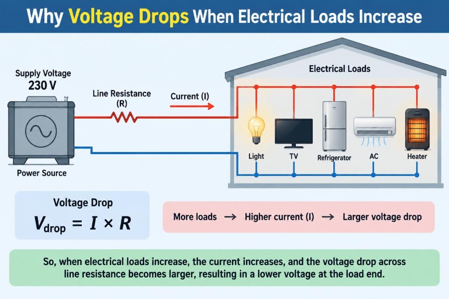

A workshop light dims for a moment when a motor starts. A laptop charger becomes unreliable at the far end of a long extension lead. In a building, equipment that works well in the morning may behave differently when many air conditioners begin running.
These are familiar signs of a basic electrical behavior: voltage at the point of use can fall as electrical load increases. The supply may still be operating normally, yet the load does not receive the voltage it needs.
Understanding the reason matters well beyond troubleshooting. Voltage drop affects conductor sizing, battery run time, motor starting, electronic reliability, heating, energy loss, and electrical safety.
The central idea is simple, but applying it requires care. A voltage drop is not caused by “using up voltage”; it is the result of current flowing through real components that have resistance, impedance, and finite source capability.
🔌 Voltage Is Electrical Potential Difference
Voltage is a difference in electric potential between two points. It is the electrical “push” that encourages charge to move through a circuit.
A useful water analogy compares voltage with pressure difference, although the analogy has limits. A higher pressure difference can drive more water through a restriction; similarly, a voltage difference can drive current through an electrical load.
What equipment experiences is not merely the voltage at a power source. It experiences the voltage across its own terminals, after any losses in wires, connectors, switches, protection devices, and the source itself.
🧲 Electrical Load Means a Demand for Current
An electrical load is anything that consumes electrical energy or converts it into another form. Lamps produce light, heaters produce heat, motors produce motion, and electronics process information.
At a fixed voltage, a lower-resistance load generally draws more current. For many common loads, power is described by:
P = V × Iwhere P is power in watts, V is voltage, and I is current in amperes. When more loads are connected in parallel, the total current drawn from the supply rises.
📐 Ohm’s Law Connects Current and Voltage Drop
The starting equation for voltage drop is Ohm’s law:
V = I × RIf current flows through any resistance, there is a voltage difference across that resistance. For a wire or connection, this is commonly written as Vdrop = I × R.
Therefore, when the current doubles through the same resistance, the voltage drop doubles. This direct relationship explains much of what happens in ordinary low-voltage and building wiring circuits.
🛣️ Every Real Conductor Has Resistance
An ideal wire would have zero resistance, but no practical conductor does. Copper and aluminum are good conductors, not perfect ones.
As current travels from the source to the load, a small voltage is lost along the outgoing conductor. It must also return through another conductor, so the complete circuit path matters.
Even a resistance too small to notice on a basic meter can create a significant drop when current becomes large. This is why a cable that is acceptable for a small sensor can be unsuitable for a motor or heating element.
📏 Longer Cable Runs Create More Drop
Resistance increases with conductor length. A load located farther from its source has more conductor in series with it, so it is more vulnerable to voltage drop.
For a two-wire circuit, calculations must include both the outgoing and return paths. A device 30 meters from its source can involve roughly 60 meters of current path before allowing for any additional connections.
This is a common source of design errors: using the one-way distance rather than the full circuit length.
🧵 Smaller Conductors Raise Circuit Resistance
Conductor cross-sectional area has the opposite effect of length. A larger conductor has lower resistance because it provides more parallel paths for charge movement.
Wire gauge labels can be confusing because numbering systems may assign lower gauge numbers to larger conductors. Rather than relying on intuition, use the manufacturer data and the applicable wiring rules for the installation.
Increasing conductor size can reduce voltage drop substantially, especially on long, high-current runs. It also usually reduces heating losses.
🌡️ Temperature Changes Resistance
For common metallic conductors, resistance generally rises as temperature rises. A cable carrying heavy current becomes warmer, its resistance increases, and the voltage drop can increase with it.
This creates a feedback effect: more current causes more heating, heating raises resistance, and higher resistance causes more loss. Normal designs account for conductor temperature ratings, installation conditions, and protective devices.
The effect does not mean every warm conductor is failing. It does mean temperature should not be ignored when evaluating circuits near their limits.
🔥 Voltage Drop Also Produces Heat Loss
Power dissipated in a resistance is given by:
Ploss = I² × RThe square on current is crucial. If current doubles, resistive heating becomes four times larger for the same resistance.
That lost power becomes heat in the cable, terminal, connector, or internal source resistance. Voltage drop is therefore not only a performance issue; it can be an efficiency and thermal-management issue as well.
🏭 The Source Has Internal Resistance Too
Power sources are not ideal voltage sources. A battery, transformer, generator, bench supply, or utility feeder has some internal resistance or, in AC systems, internal impedance.
When load current rises, voltage can drop inside the source before electricity even reaches the external wiring. A battery’s terminal voltage, for example, may sag noticeably under a large load and recover partly when the load is removed.
This is why measurements at the source terminals and at the load terminals tell different parts of the story.
🔋 Battery Voltage Sag Under Heavy Load
A battery has an open-circuit voltage, measured with little or no load, and a loaded terminal voltage, measured while it supplies current. The open-circuit reading alone does not reveal how the battery will behave in service.
Internal resistance tends to increase as many batteries discharge, age, or become cold. A device may shut down because its undervoltage protection sees a sagging terminal voltage even though the battery later appears to “recover.”
Battery chemistry, state of charge, temperature, and protection circuitry all influence the result. A voltage sag should not automatically be blamed on the battery without checking cables and connections.
⚙️ Motors Demand Extra Current at Startup
Motors are a frequent cause of brief voltage dips. At startup, a motor has not yet developed normal back electromotive force, so it can draw much more current than it does at steady running speed.
That high inrush current produces a larger drop across supply impedance and wiring resistance. Lights may flicker, electronic controls may reset, or a weak source may fail to start the motor.
Once the motor reaches speed, current often falls and voltage recovers. The short duration does not make the event irrelevant; repeated starts and sensitive loads may still require attention.
💡 Why Lamps Dim When a Large Load Starts
Suppose a lamp and a motor share part of a branch circuit. When the motor starts, its current rises sharply, creating a larger voltage drop in the shared upstream wiring.
The lamp sees less terminal voltage and its light output may fall briefly. Incandescent lamps show this clearly, while LED behavior depends on the driver design and may range from no visible change to flicker or temporary shutdown.
The lamp is not necessarily defective. It is revealing a change in supply voltage at its terminals.
🧮 A Simple DC Voltage-Drop Example
Consider a hypothetical 12 V load drawing 10 A through a pair of conductors whose combined round-trip resistance is 0.20 Ω. The voltage drop in the conductors is:
Vdrop = 10 A × 0.20 Ω = 2 VThe load receives about 10 V rather than 12 V, assuming the source itself remains at 12 V under load. The wiring also dissipates:
Ploss = 10² × 0.20 Ω = 20 WTwenty watts distributed along a cable may be noticeable, and if concentrated at a poor terminal it can become a serious warning sign.
🌊 AC Circuits Add Impedance to the Picture
In alternating-current circuits, resistance is not the full story. Conductors, transformers, motors, and other components can have impedance, the combined opposition arising from resistance and frequency-dependent reactance.
Inductive loads such as motors and transformers can shift the timing between voltage and current. This affects the voltage drop calculation and is one reason AC feeder design may use impedance data rather than resistance alone.
For short, ordinary circuits, resistance may provide a useful first estimate. For larger systems, long runs, high currents, or significant motor loads, a proper AC analysis is needed.
📊 Power Factor Changes AC Current Demand
Power factor describes how effectively AC current is converted into useful real power. With a lower power factor, more current may be required to deliver the same real power at the same voltage.
More current increases voltage drop and conductor heating. This does not mean all low-power-factor equipment is inherently bad; it means the system must be designed for the current it actually draws.
Power factor correction can help in suitable industrial and commercial applications, but it must be engineered for the specific load and network. It is not a universal fix for all voltage problems.
🔗 Loose Connections Behave Like Hidden Resistors
Terminals, plugs, switches, breakers, fuse holders, splices, and crimp joints all add some resistance. A clean, correctly tightened connection has very low resistance; a loose, corroded, damaged, or poorly made connection can have much more.
Because heating follows I²R, a small high-resistance point can become much hotter than the cable around it. This may cause discoloration, odor, intermittent operation, melted insulation, or equipment damage.
Do not treat a hot connector as a normal voltage-drop issue. De-energize the equipment where safe to do so and have a qualified person inspect it.
🧰 Connectors and Extension Leads Are Part of the Circuit
An extension lead is not electrically invisible. Its length, conductor size, plug condition, reel arrangement, and connection quality all affect voltage at the load.
A long, lightweight extension lead may work for a small charger but cause poor performance with a high-current tool. Cable reels can also overheat if heavily loaded while tightly wound because heat cannot dissipate effectively.
Choose a lead rated for the intended environment and load, and follow its instructions. Never solve a recurring voltage problem by chaining multiple extension leads together.
🏠 Shared Wiring Creates Shared Effects
In homes and small facilities, multiple outlets may share a branch circuit. Their currents combine in common conductors upstream of the individual outlets.
One heavy load can therefore influence voltage seen by other devices on that branch. This is especially noticeable where conductors are long, source impedance is high, or large intermittent loads operate.
Separating heavy loads onto appropriately designed circuits can improve performance, but circuit changes must follow local electrical requirements and be performed by competent installers.
🏗️ Distribution Systems Have Their Own Limits
Voltage drop can occur at several levels: within a device, along a branch circuit, in a feeder, across a transformer, and upstream in the distribution network. A problem at one level can resemble a problem at another.
Large installations manage this through coordinated conductor sizing, transformer selection, protection, load balancing, and voltage regulation. The objective is not zero voltage drop, which is impractical, but acceptable voltage at equipment under expected operating conditions.
Supply systems also experience changing demand. The utility service voltage may vary within its operating arrangements, while a building’s own wiring can add further drop.
⚖️ Balanced and Unbalanced Three-Phase Loads
Three-phase systems distribute power efficiently, particularly for motors and larger equipment. When loads are balanced across phases, phase currents are similar and the system operates as intended.
Unbalanced loading can cause unequal voltage drops, particularly in systems with a neutral conductor. Some equipment may then receive lower or higher voltage than expected relative to the other phases.
Balancing is not simply an accounting exercise. It reduces uneven stress on conductors and can improve voltage performance across the installation.
🖥️ Sensitive Electronics May React Before Humans Notice
Many electronic devices contain power supplies that tolerate a range of input voltage, but their limits differ. Some ride through a short dip; others reset, shut down, produce errors, or reduce output.
Network equipment, controls, medical equipment, data systems, and industrial automation may need a more detailed power-quality assessment than a simple voltage reading can provide. Brief dips, waveform distortion, and transients may matter as much as average voltage.
Do not assume a surge protector corrects voltage sag. Surge protection and voltage regulation address different disturbances.
📉 Undervoltage Can Change Load Behavior
Not every load responds to low voltage in the same way. A resistive heater generally draws less current and produces less heat when voltage falls. An incandescent lamp becomes dimmer.
Some motor loads can draw unfavorable current or run hotter if they operate for long periods below their designed voltage, depending on the motor and driven load. Electronic constant-power devices may draw more current as input voltage decreases, within their operating range.
This distinction matters because “low voltage means low current” is not a safe universal assumption.
🧭 Measuring at the Right Points
A useful troubleshooting method is to measure voltage at the source and at the load while the load is operating. A large difference between those readings points toward loss in the intervening circuit.
Measurements should be made with properly rated instruments and appropriate safety practices. Exposed energized conductors, panels, and high-energy systems present hazards that require qualified personnel.
For intermittent issues, a meter with minimum/maximum capture, a data logger, or a power-quality instrument may reveal dips that a single manual reading misses.
🔍 A Practical Diagnostic Sequence
Voltage-drop troubleshooting works best when it follows the current path rather than guessing from symptoms.
- Identify when the problem occurs: steady load, startup, peak demand, or a specific device operation.
- Measure source voltage and load-terminal voltage under the same operating condition.
- Inspect accessible plugs, terminals, connectors, and cables for heat damage, corrosion, looseness, or mechanical strain.
- Measure or calculate current, then compare it with equipment ratings and circuit design information.
- Isolate sections of the path to determine whether the drop is in the source, protection device, cable, connection, or load.
A measurement without load is often insufficient. Many faults become visible only when meaningful current flows.
🧮 Estimating Acceptable Voltage Drop
Design guidance often sets recommended voltage-drop limits for particular parts of an installation, but the appropriate target depends on local codes, equipment requirements, cable type, load characteristics, and the overall system design.
Rather than applying one number blindly, start with the equipment’s permitted supply-voltage range. Then account for normal operation, motor starting, conductor temperature, future load growth, and the voltage available at the supply point.
For regulated industries and fixed wiring, applicable codes and standards take priority over informal rules of thumb.
🛠️ Reducing Drop by Improving the Path
The most direct way to reduce voltage drop is to reduce circuit resistance or impedance. Practical options include shortening the route, using larger conductors, improving connections, and placing the source closer to the load.
Other solutions depend on the system:
- Use a supply with adequate current capability and transient response.
- Provide a dedicated circuit for a large or sensitive load.
- Use soft starters, variable-speed drives, or other suitable motor-starting methods where appropriate.
- Balance phase loads in three-phase systems.
- Use local energy storage or regulated conversion only when it is designed for the load and fault conditions.
Each change can introduce cost, protection, thermal, and compliance considerations. The best fix addresses the actual bottleneck, not merely the visible symptom.
🚫 Common Misconceptions to Avoid
One misconception is that current “gets used up” as it travels to a load. In a series path, current is the same through each component at a given instant; energy is transferred, while voltage is divided among impedances.
Another is that a higher-rated breaker fixes voltage drop. A breaker protects conductors and equipment against overcurrent under defined conditions. Installing an incorrectly larger breaker can remove protection and create a fire or equipment hazard.
It is also mistaken to judge a circuit only by whether it works. A device may operate while receiving poor voltage, overheating connections, or stressing motors and power supplies.
🧯 When Voltage Drop Becomes a Safety Concern
Normal, calculated voltage drop is expected in real systems. Abnormal voltage drop, especially at one connector or terminal, can indicate a fault that generates dangerous heat.
Warning signs include repeated breaker trips, buzzing or arcing sounds, hot plugs, burnt smells, discolored outlets, flickering that is new or severe, and equipment that cycles or resets under load.
Turn off and stop using suspect equipment if it can be done safely. Electrical inspection and repair should be performed by a qualified electrician or technician, particularly for fixed wiring, panels, high-current circuits, or battery systems capable of high fault current.
📝 Designing for Real Operating Conditions
Good electrical design starts with the expected load profile, not just a nameplate power figure. Consider continuous operation, simultaneous loads, startup current, ambient temperature, cable routing, grouping, voltage tolerance, and planned expansion.
A circuit that appears adequate at room temperature with one load may perform poorly when enclosed in a hot conduit, shared with other circuits, and asked to start a motor during peak facility demand.
Design margin is not waste when it prevents nuisance shutdowns, overheating, and costly rework. It is a deliberate response to real-world variation.
🎯 The Core Principle: Current Reveals Weaknesses
Voltage drops when electrical loads increase because higher load current produces a larger voltage loss across the resistance and impedance of the entire supply path. That path includes the source, conductors, connections, protection devices, and distribution equipment.
The key relationship is simple: more current through a given impedance means more voltage drop. The consequences, however, vary with load type. A lamp may dim, a battery-powered device may shut down, a motor may struggle to start, and a poor connection may overheat.
Reliable systems manage voltage drop through appropriate source capacity, conductor selection, connection quality, sensible circuit layout, and measurements taken under real load conditions.
When a voltage falls under load, follow the current path and look for the resistance or impedance that the current is exposing. That approach turns a vague symptom into a solvable engineering problem. ⚡🔧