
A power station may be many kilometres from the homes, hospitals, factories, and data centres that need its electricity. Getting energy from one place to another sounds straightforward until current begins flowing through long conductors.
Every line has resistance, and resistance turns some electrical energy into heat. If a transmission network carried very large current at a low voltage, those losses and the size of the conductors would become impractical.
Transformers solve this problem without relying on moving mechanical parts. They raise voltage for efficient transmission, lower it for safe and useful consumption, and connect different parts of a power system at appropriate voltage levels.
Understanding how a transformer works explains much more than a device in a substation. It reveals why distribution networks have their familiar shape, why frequency matters, and why engineers pay close attention to insulation, magnetic cores, and fault protection. ⚡
⚡ 1. The voltage journey from generation to use
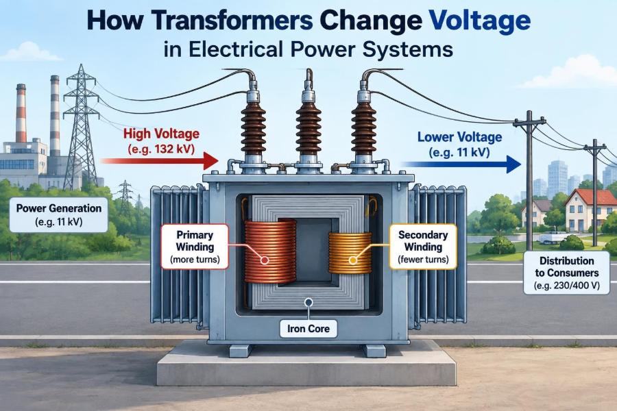
Electrical power usually passes through several voltage stages before it reaches an end user. A generator produces electricity at one voltage, a step-up transformer raises it for transmission, and later transformers progressively reduce it for regional, local, and equipment-level use.
This sequence is called voltage transformation. It lets each part of the system operate at a voltage suited to its main job rather than forcing generation, transmission, and utilisation to use one compromise voltage.
- Generation requires practical machine insulation and construction.
- Transmission benefits from high voltage and comparatively low current.
- Consumer equipment requires voltages compatible with safe wiring and appliance design.
🔌 2. Why changing voltage changes current
For an ideal AC system, real power is approximately the product of voltage and current. In a single-phase circuit, this relationship is expressed as P = VI cos φ, where cos φ accounts for power factor.
If the same amount of power is delivered at a higher voltage, less current is needed. In three-phase systems, the familiar form is P = √3 VLLI cos φ, where VLL is line-to-line voltage.
Lower current is valuable because conductor heating depends strongly on current. That connection is the fundamental engineering reason transformers are central to power networks.
🔥 3. The importance of I²R losses
A conductor with resistance R dissipates heat at a rate given by Ploss = I²R. Doubling current therefore makes resistive loss four times larger, assuming resistance stays the same.
Consider a line delivering a fixed power level. Raising its voltage allows current to fall, which sharply reduces the heat lost in the line and the associated voltage drop.
Engineers can also reduce resistance by choosing larger conductors, but this adds material, structural, and installation cost. Increasing voltage through transformers is often the more effective system-level solution. 🔥
🧲 4. The basic parts of a transformer
A conventional power transformer has two electrically separate windings wound around a magnetic core. The winding connected to the source is the primary winding, while the winding supplying the load is the secondary winding.
The core provides a low-reluctance path for changing magnetic flux. Laminated steel cores are common at power frequency because laminations limit unwanted circulating currents within the core material.
- Primary winding: receives electrical energy.
- Magnetic core: guides the alternating magnetic flux.
- Secondary winding: delivers energy at a transformed voltage.
- Insulation and enclosure: maintain electrical separation and manage the environment.
🌊 5. Mutual induction: the operating principle
When alternating voltage is applied to the primary winding, an alternating magnetising current creates changing magnetic flux in the core. That changing flux links both windings.
According to Faraday’s law, a changing magnetic flux induces an electromotive force in a conductor. The secondary winding therefore develops a voltage even though it has no direct conductive connection to the primary winding.
This is mutual induction. Energy transfers through the magnetic field, while the windings remain galvanically isolated from one another.
➰ 6. Turns ratio determines the voltage ratio
The most important ideal transformer relationship compares winding turns and voltage. If Np and Ns are the primary and secondary turns, then:
V_p / V_s = N_p / N_s
A secondary winding with more turns than the primary has a higher induced voltage. A secondary with fewer turns has a lower induced voltage, provided the transformer is operating within its intended conditions.
The turns ratio is fixed by construction. A tap changer can alter the effective number of turns used, allowing controlled adjustment of the output ratio.
⬆️ 7. What a step-up transformer does
A step-up transformer has more turns on its secondary than on its primary. It raises voltage from the source-side level to a higher level suitable for the next stage of the network.
At a generating station, a generator step-up transformer commonly connects the generator bus to a transmission system. The higher voltage enables a given power output to travel with lower line current.
Step-up does not create power. In an ideal transformer, the increased voltage is accompanied by a proportionate reduction in current.
⬇️ 8. What a step-down transformer does
A step-down transformer has fewer secondary turns than primary turns. It reduces voltage while making more current available at the lower-voltage side for the same approximate power transfer.
Distribution substations use step-down transformers to move from subtransmission levels to local distribution levels. Smaller transformers then lower voltage again for buildings, controls, and electronic equipment.
The term “step-down” describes voltage only. The device still transfers energy from input to output, subject to its losses and rating.
⚖️ 9. Voltage rises while current falls
For an ideal transformer, apparent power is conserved:
V_p I_p = V_s I_s
Combining this with the turns ratio gives an inverse current relationship. A voltage increase by a certain ratio corresponds to a current decrease by that same ratio, and vice versa.
Real transformers need a small input current even with no external load because the core must be magnetised. They also have losses, so output power is slightly lower than input power.
🔄 10. Why transformers require changing flux
A transformer needs changing magnetic flux to induce secondary voltage. Alternating current continuously reverses and varies the flux, making ordinary power-frequency transformers naturally compatible with AC systems.
If steady DC is connected to a conventional transformer primary, there is only a brief changing-flux event while conditions change. After that, the flux no longer changes enough to induce the intended secondary voltage.
Worse, DC can drive the core toward saturation, causing excessive primary current limited mainly by winding resistance and source impedance. This may rapidly overheat or damage the transformer.
📐 11. Frequency affects transformer design
The applied voltage, number of turns, core area, and frequency are linked. At a lower frequency, a transformer generally needs more turns, a larger core, or a lower applied voltage to avoid excessive core flux.
That is why a transformer designed for one frequency must not automatically be used at a lower frequency and its full rated voltage. The resulting flux density could be too high.
Higher-frequency transformers can be much smaller for a given power rating, which is one reason switched-mode power supplies first convert electrical energy to high-frequency AC before transforming it.
🧱 12. The magnetic core and its role
The core concentrates magnetic flux so that most of the flux produced by the primary links the secondary. Without a magnetic core, coupling would be weak and the transformer would need a very different, less efficient construction.
Core materials are selected for high magnetic permeability and manageable losses. Power-frequency units commonly use thin insulated laminations, while high-frequency designs may use ferrite materials.
A properly designed core stays below its intended saturation region during normal operation. This preserves predictable magnetising current and reduces distortion.
🌀 13. Eddy currents and laminated steel
Changing flux can induce currents not only in windings but also within a solid conductive core. These circulating currents are called eddy currents, and they produce unwanted heating.
Stacking thin steel sheets with insulating coatings interrupts many possible eddy-current paths. The thin laminations greatly increase resistance to currents circulating across the core thickness.
Core steel also experiences hysteresis loss as its magnetic domains repeatedly reverse. Material choice, flux density, and frequency all influence the total core loss.
💡 14. No-load current is normal
An unloaded transformer is not completely inactive. Its primary draws a no-load current to establish flux in the core and supply core losses.
This current has a magnetising component, which is largely reactive, and a loss component associated with hysteresis and eddy-current losses. It is usually far smaller than rated load current, but it matters in system studies.
When a transformer is energised, the first few cycles can produce a much larger transient called inrush current. Protection schemes must distinguish expected inrush behaviour from internal faults.
📉 15. Real transformers have voltage drop
Actual windings have resistance and leakage reactance. When load current flows, these internal impedances cause a difference between no-load secondary voltage and loaded secondary voltage.
This behaviour is described by voltage regulation. A transformer with good regulation keeps its secondary voltage relatively close to its nominal value as the load changes.
The exact voltage change also depends on load power factor. Inductive and capacitive loads interact differently with transformer reactance, so their voltage effects are not identical.
🌡️ 16. Transformer losses become heat
Transformer losses are commonly grouped into core losses and winding losses. Core losses occur whenever the transformer is energised, while winding losses increase approximately with the square of load current.
| Loss category | Main cause | How it changes with load |
|---|---|---|
| Core loss | Hysteresis and eddy currents in the magnetic core | Present at no load; mainly tied to voltage and frequency |
| Copper loss | Resistance in primary and secondary windings | Increases strongly as current rises |
| Stray loss | Leakage-flux effects in windings and structural parts | Generally rises with load current |
Heat must be removed to keep insulation within its allowable operating temperature. Thermal design is therefore inseparable from electrical design. 🌡️
🛢️ 17. Cooling and insulation protect the transformer
Small transformers may use air cooling and solid insulation. Larger power transformers often use insulating liquid to improve heat transfer and provide dielectric strength between high-voltage parts.
Radiators increase the surface area available for heat release. Some designs use fans or pumps when natural convection is insufficient for the required rating.
Insulation ages faster at elevated temperature. Controlling hot spots, moisture, contamination, and overloading helps preserve transformer life and reliability.
🏭 18. Transformers across the power-system chain
Power systems use transformers at many scales, from large grid units to compact instrument transformers. Their locations reflect the need to exchange power between networks operating at different voltages.
Common locations
- Generator step-up transformers connect generation to transmission networks.
- Grid and substation transformers interconnect transmission and subtransmission levels.
- Distribution transformers supply streets, commercial buildings, and residential areas.
- Service and control transformers provide lower voltages for equipment and auxiliary systems.
Each design is selected for a particular duty cycle, insulation level, impedance, cooling method, and installation environment.
🏘️ 19. Distribution transformers near consumers
Distribution transformers are the familiar final major voltage-conversion stage before low-voltage service. They may be pole-mounted, pad-mounted, installed in kiosks, or housed within buildings.
They are designed for long energised periods and varying customer demand. Their core loss matters because it exists whenever they remain connected to the network, even during light-load hours.
Utilities choose ratings and placement to balance voltage quality, capacity, network expansion, and practical access for maintenance.
🔺 20. Three-phase transformer connections
Most bulk electric power is transmitted and distributed as three-phase AC. Three single-phase transformer units can be connected as a bank, or all three phases can be incorporated into one three-phase transformer.
Common winding connections include star, also called wye, and delta. The selected connection affects neutral availability, phase shift, insulation requirements, harmonic behaviour, and response to unbalanced loads.
- Wye connections can provide a neutral point for grounded systems and phase-to-neutral loads.
- Delta connections provide a closed path for certain harmonic currents and can support some unbalanced conditions.
Connection choice is a system-design decision, not merely a wiring preference.
🎛️ 21. Tap changers regulate voltage
Network voltage varies with load, generation, and line conditions. A transformer can compensate for part of this variation by changing the effective turns ratio through taps.
An off-circuit tap changer is operated only when the transformer is de-energised. An on-load tap changer can change taps while carrying load, using a switching arrangement designed to avoid interrupting supply.
Automatic voltage control may command on-load tap changes to maintain a target bus voltage within a chosen operating range.
🧪 22. Isolation is as important as transformation
A transformer can provide galvanic isolation because its primary and secondary are not electrically connected by a conductor. The energy path is magnetic rather than direct conductive contact.
Isolation can improve safety, reduce certain ground-loop problems, and allow circuits with different reference potentials to exchange power. However, isolation does not eliminate all hazards: high secondary voltage, stored energy, and capacitive coupling can still be dangerous.
Some transformers are designed primarily for isolation with approximately equal input and output voltage. Voltage ratio and isolation are related capabilities, but they are not the same requirement.
📏 23. Nameplate ratings guide correct use
A transformer nameplate identifies the conditions for which it was designed. Typical information includes rated apparent power, primary and secondary voltages, frequency, phase arrangement, connection details, impedance, cooling information, and tap data.
Ratings are normally stated in volt-amperes rather than watts because transformer heating depends mainly on voltage and current, while the load power factor may vary.
Engineers should not assume that a transformer can safely deliver any load merely because its output voltage is suitable. Current rating, insulation, fault duty, environment, and cooling all matter.
🛡️ 24. Protection addresses internal and external faults
Transformers can experience overloads, short circuits, insulation failures, overheating, and abnormal flux conditions. Protective devices are selected to detect these problems and isolate equipment when needed.
Large units may use differential protection, which compares electrical quantities entering and leaving the protected zone. Other schemes can monitor overcurrent, temperature, gas generation in liquid-filled equipment, pressure, or excessive volts-per-hertz conditions.
Protection must be coordinated with the rest of the network. It should respond quickly to genuine faults while remaining secure during load changes, external faults, and magnetising inrush.
⚠️ 25. Common misconceptions about transformers
One misconception is that a step-up transformer “adds energy” because its output voltage is higher. In reality, voltage rises as available current falls, and losses mean output power is never greater than input power.
Another is that transformers work with any electrical supply. Conventional transformers require alternating flux, so steady DC is unsuitable unless electronic switching converts it into a changing waveform first.
A third misconception is that every transformer is perfectly isolated. Autotransformers use a shared winding, so they can transform voltage efficiently but do not provide the same galvanic separation as separate-winding transformers.
🔗 26. Autotransformers and special-purpose designs
An autotransformer has one winding with taps shared by input and output. Because part of the power transfer is conductive as well as magnetic, it can be smaller and more efficient for some voltage ratios.
Its important limitation is the lack of full galvanic isolation. A fault or unwanted connection on one side can have implications for the other side, so application assessment is essential.
Other specialised designs include current transformers for measurement, voltage transformers for instrumentation, grounding transformers, welding transformers, and high-frequency transformers in electronic converters.
📊 27. Measuring high currents and voltages safely
Instrument transformers scale system quantities to levels suitable for meters, relays, and monitoring equipment. A current transformer, or CT, produces a secondary current proportional to primary current.
A voltage transformer, often called a potential transformer in some contexts, produces a reduced and isolated representation of system voltage. These devices let protective relays and instruments observe high-energy circuits without direct connection to measurement hardware.
CT secondary circuits require special care. Opening a CT secondary while its primary carries current can create a dangerously high secondary voltage, so established safety procedures are essential.
🌍 28. Transformers enable interconnected power systems
Interconnected grids contain equipment designed at different voltage levels and serve loads spread across broad areas. Transformers make those networks practical by creating controlled interfaces between voltage zones.
They also help engineers manage short-circuit current and voltage performance because transformer impedance affects how faults and load changes propagate through a system. This makes transformer selection part of network planning, not simply a matter of choosing a voltage ratio.
From renewable-energy collector systems to industrial plants, transformation allows electrical energy to move between the voltage levels that each system component can use effectively.
✅ 29. The core principle to remember
A transformer changes AC voltage by using a changing magnetic flux to induce voltage in a second winding. The winding turns ratio sets the ideal voltage ratio, while the current ratio changes inversely.
Step-up transformation reduces current for efficient long-distance power transfer. Step-down transformation provides lower, usable voltages closer to loads, with insulation, cooling, regulation, and protection ensuring dependable operation.
Transformers do not create power: they trade voltage for current while transferring energy through magnetic induction. ⚡🧲🔌