
Electrical systems are designed to move large amounts of energy safely through conductors, switches, transformers, motors, panels, and protective devices. Most of the time, that energy remains confined inside insulated wires and properly enclosed equipment.
But when electrical current unexpectedly jumps through air between energized conductors—or between a conductor and ground—the result can be an electric arc.
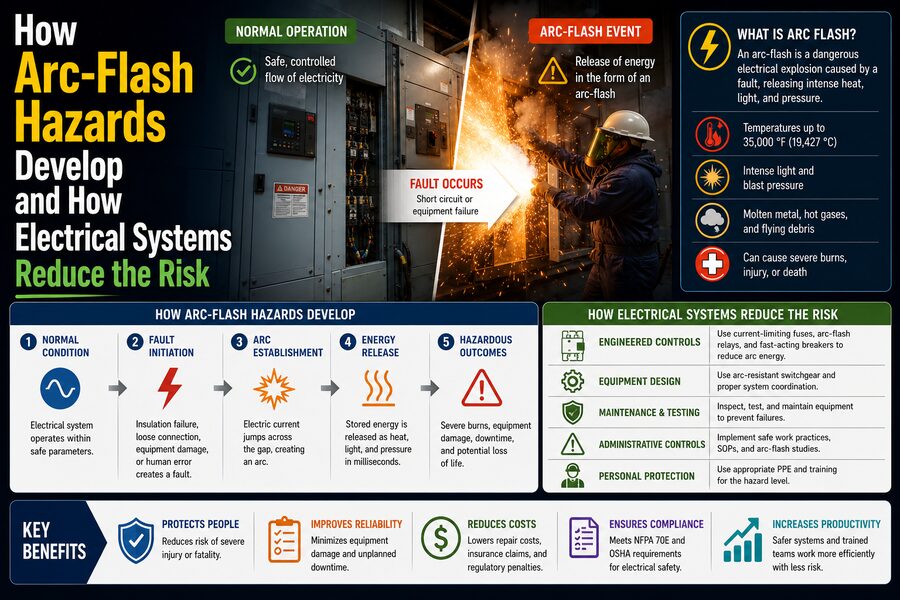
If the available electrical energy is high enough, that arc can develop into an arc flash: an extremely rapid release of heat, light, pressure, molten metal, and hot gases. ⚠️🔥
An arc-flash event can reach enormous temperatures in a fraction of a second. It can damage switchgear, ignite clothing, eject metal particles, create a pressure wave, and cause severe injury to anyone standing nearby.
For this reason, electrical engineers do not rely on a single protective measure.
Modern systems reduce arc-flash risk using:
- Fast fault detection
- Circuit breakers and fuses
- Current-limiting protection
- Protective relays
- Arc-resistant equipment
- Remote operation
- Proper maintenance
- Equipment labeling
- Safe work practices
- Personal protective equipment
The central engineering goal is simple:
If an electrical fault creates an arc, detect it quickly and remove energy before the event becomes catastrophic. ⚡🛡️
🧠 What Is an Electrical Arc?
Under normal conditions, air behaves as an electrical insulator.
That is why two energized conductors can be separated by air without current automatically flowing between them.
However, if voltage becomes high enough or the air becomes contaminated, heated, ionized, or bridged by conductive material, the insulation strength of the air can break down.
Current can then flow through an ionized path.
This glowing path is called an electric arc.
Once an arc forms, the surrounding air becomes extremely hot and conductive.
That can allow the arc to continue even though the original initiating contact or contamination has disappeared.
🔥 What Makes an Arc Flash So Dangerous?
An arc flash is dangerous because electrical energy is converted into multiple damaging effects almost instantly.
These include:
🔥 Extreme thermal energy
💥 Rapid pressure rise
🌟 Intense visible and ultraviolet light
🔊 Loud acoustic energy
🧲 Electromagnetic forces
🔩 Molten and vaporized metal
An electrical cabinet that appears quiet one moment can become an extremely energetic environment almost instantly.
The severity depends on factors such as:
- System voltage
- Available fault current
- Arc duration
- Electrode spacing
- Equipment enclosure
- Working distance
- Protective-device clearing time
A high-current fault that persists for one second can release dramatically more energy than the same fault cleared in a few milliseconds.
That is why fault-clearing speed is one of the most important concepts in arc-flash protection.
🌡️ Arc Temperatures Can Become Extremely High
The plasma inside an electrical arc can reach temperatures of many thousands of degrees Celsius.
At such temperatures:
🔩 Copper can melt and vaporize
⚙️ Steel components can be damaged
🧴 Plastic insulation can decompose
🔥 Nearby combustible materials can ignite
When metal vaporizes, it expands rapidly.
This contributes to pressure buildup inside enclosed electrical equipment.
The thermal hazard alone can cause severe burns, but the event can also become a mechanical hazard.
💥 Arc Blast vs. Arc Flash
The terms arc flash and arc blast are related but describe different aspects of the same event.
🔥 Arc Flash
Refers primarily to the intense thermal and radiant energy released by the arc.
💥 Arc Blast
Refers to the pressure wave and mechanical force associated with the rapidly expanding gases and vaporized material.
The pressure wave can:
- Throw a worker backward
- Damage hearing
- Dislodge equipment covers
- Eject metal fragments
- Damage nearby structures
In high-energy systems, these mechanical effects can be severe.
⚙️ How Does an Arc-Flash Event Begin?
An arc flash usually begins with an abnormal electrical condition.
Possible causes include:
🔧 Accidental tool contact
🪛 Dropped conductive objects
🐀 Animal intrusion
💧 Moisture
🌫️ Dust contamination
⚡ Insulation failure
🔩 Loose connections
🧱 Equipment deterioration
👷 Human error during maintenance
Imagine a technician working inside an energized panel.
A metal tool accidentally bridges two energized conductors.
For a brief instant, a very large current flows through the tool.
The metal heats rapidly.
It may melt or vaporize.
The surrounding air becomes ionized.
Even after the tool moves away, current may continue flowing through the hot plasma.
The accidental short circuit has now become an electrical arc.
🔄 Why an Arc Can Sustain Itself
Once air becomes ionized, it becomes much more conductive.
The arc heats the air.
The hot air releases charged particles.
Those particles allow more current to flow.
More current produces more heating.
This creates a reinforcing process:
Initial fault ⚠️
⬇️
Air ionizes
⬇️
Current flows through plasma ⚡
⬇️
More heat is generated 🔥
⬇️
More ionization occurs
⬇️
Arc continues
The arc may also move along conductors or spread between phases.
This is one reason an initial small fault can escalate rapidly.
⚡ Available Fault Current Matters
The amount of current available from the electrical source strongly influences arc severity.
Consider two systems.
A small residential circuit may have relatively limited fault current.
A large industrial switchboard connected close to a powerful transformer may have tens of thousands of amperes available during a fault.
The larger system can feed vastly more energy into an arc.
Factors affecting available fault current include:
- Transformer size
- Transformer impedance
- Generator capacity
- Utility supply strength
- Conductor impedance
- System configuration
Engineers calculate fault current during electrical-system design so protective equipment can be properly selected.
⏱️ Arc Duration Can Matter as Much as Current
A common misconception is that the highest-current system is always the most dangerous.
Arc-flash energy also depends heavily on how long the arc remains energized.
Suppose one fault produces:
30,000 A for 0.05 seconds
while another produces:
15,000 A for 2 seconds.
The second event may expose a worker to much more energy because it lasts dramatically longer.
Protective-device response time therefore becomes critical.
A breaker that operates quickly can drastically reduce incident energy.
🛡️ Circuit Breakers Are a Primary Defense
Circuit breakers are designed to interrupt abnormal electrical current.
When a fault occurs, the breaker detects or receives a trip command and opens the circuit.
The process is:
Fault develops ⚠️
⬇️
Protection detects abnormal current
⬇️
Breaker receives trip command
⬇️
Contacts open
⬇️
Current is interrupted
⬇️
Arc loses its energy source
The faster this happens, the less energy can be released.
🔥 Fuses Can Provide Very Fast Protection
Fuses are another major protective technology.
A fuse contains an element designed to melt when excessive current flows.
Once the element melts, the circuit opens.
Certain current-limiting fuses can interrupt extremely high fault currents before the current reaches its theoretical maximum.
This can reduce:
⚡ Peak current
🔥 Thermal energy
💥 Mechanical stress
🔩 Equipment damage
In appropriate applications, fast current-limiting fuses can significantly reduce arc-flash exposure.
🧠 Protective Relays Make Intelligent Decisions
Large industrial and utility electrical systems often use protective relays.
These electronic devices monitor electrical quantities such as:
- Current
- Voltage
- Frequency
- Direction of power flow
- Differential current
- Ground current
When the relay detects a fault pattern, it commands a circuit breaker to open.
Modern digital relays can perform sophisticated protection functions in milliseconds.
They can also record fault data, helping engineers determine what happened after an event.
👀 Arc-Flash Detection Relays Can Use Light
Some systems include dedicated arc-flash relays.
These devices may use optical sensors installed inside switchgear.
An arc produces an intense burst of light.
The relay can detect this light extremely quickly.
However, light alone could potentially come from another source.
For greater reliability, some systems require both:
High current + intense light
before issuing a trip.
When both conditions occur simultaneously, the system can identify a likely internal arc fault and trip the breaker very rapidly. ⚡🌟
This can reduce arc duration significantly.
⏱️ Why Milliseconds Matter
Arc-flash protection is a race against time.
Suppose a protective device clears a fault in:
500 milliseconds
and an improved protection scheme clears it in:
50 milliseconds.
The energy release can be dramatically lower in the faster system.
This is why engineers focus intensely on relay response, breaker opening time, and coordination settings.
A difference measured in tenths of a second can have enormous consequences.
📊 What Is Incident Energy?
Arc-flash studies often calculate incident energy.
Incident energy estimates the amount of thermal energy that could reach a surface at a specified working distance from the arc.
It is commonly expressed in units such as:
cal/cm²
or equivalent energy-per-area units.
This number helps engineers determine:
- Hazard boundaries
- PPE requirements
- Equipment labels
- Whether additional mitigation is needed
Incident energy depends on multiple system parameters and is not simply the same as short-circuit current.
📐 Working Distance Changes Exposure
The farther a person is from the arc, the lower the thermal exposure generally becomes.
This is why working distance is included in arc-flash calculations.
A worker whose face and torso are close to open switchgear may receive much more incident energy than someone operating the same equipment from several meters away.
This leads directly to an important mitigation strategy:
Increase distance whenever practical.
Remote switching and remote racking systems are designed around this principle.
🎛️ Remote Operation Keeps Workers Away
Some electrical equipment can be operated remotely.
Instead of standing directly in front of a breaker, a worker may use a remote control device from outside the arc-flash boundary.
Remote systems can operate:
⚡ Circuit breakers
🔩 Disconnects
🧰 Racking mechanisms
🛠️ Motor control equipment
The electrical equipment still experiences the same fault if something goes wrong, but the worker is farther away.
Distance is one of the most reliable ways to reduce human exposure.
🧱 Arc-Resistant Switchgear Contains Energy
Ordinary electrical cabinets may allow pressure and hot gases to escape toward the worker.
Arc-resistant switchgear is designed differently.
It may include:
- Reinforced enclosures
- Stronger doors
- Pressure-relief channels
- Internal barriers
- Directed exhaust paths
If an internal arc occurs, the equipment attempts to contain or redirect the dangerous products away from normal operating positions.
For example, hot gases may be vented upward through a dedicated plenum instead of toward someone standing in front of the switchboard.
Arc-resistant equipment does not prevent every arc.
Its purpose is to better control the consequences.
🧲 Bus Differential Protection Can Clear Faults Quickly
Large switchboards and substations may use differential protection.
Current transformers measure current entering and leaving a protected zone.
Under normal conditions:
Current entering ≈ current leaving
If a fault occurs inside the protected zone, the difference becomes significant.
The relay interprets this as an internal fault and trips the relevant breakers.
Differential protection can be extremely fast because it does not need to wait for conventional time-delayed overcurrent coordination.
This makes it valuable for high-energy electrical buses.
🎚️ Maintenance Mode Can Reduce Trip Delay
Electrical systems often coordinate protective devices so that the breaker closest to a fault trips first.
This is called selective coordination.
For example:
Branch breaker → feeder breaker → main breaker
The upstream main breaker may intentionally wait longer before tripping so a downstream device has time to clear the fault.
This improves continuity—but it can increase arc-flash energy near the main equipment.
Some systems therefore use an arc-flash reduction maintenance switch or maintenance mode.
When maintenance personnel are working nearby, the system temporarily uses faster trip settings.
This sacrifices some selectivity in exchange for reduced incident energy.
⚖️ Protection Coordination Creates an Engineering Tradeoff
Electrical protection must balance two important goals:
🎯 Selectivity
Only the protective device nearest the fault should trip.
⚡ Speed
The fault should be removed as quickly as possible.
If every breaker trips instantly, a small branch fault might shut down an entire facility.
If upstream breakers wait too long, arc-flash energy can increase.
Protection engineers therefore use coordination studies to find an appropriate balance.
🧮 Arc-Flash Studies Evaluate the System
An arc-flash study analyzes an electrical distribution system to estimate hazard levels.
Engineers gather information about:
- Transformers
- Breakers
- Fuses
- Cable lengths
- Equipment ratings
- Protective settings
- System voltage
- Utility fault contribution
- Generator contribution
Software models the system and calculates likely fault behavior at many locations.
The study may determine:
📊 Available fault current
⏱️ Clearing time
🔥 Incident energy
📐 Arc-flash boundary
🛡️ Required protective measures
The results are used to improve both system design and worker safety.
🏷️ Equipment Labels Communicate Hazard Information
After an arc-flash analysis, electrical equipment may receive warning labels.
Depending on applicable standards and workplace policies, a label may provide information such as:
⚡ System voltage
🔥 Incident-energy level
📐 Arc-flash boundary
🛡️ PPE guidance
⚠️ Hazard warnings
The purpose is to help workers understand that opening or servicing energized equipment may expose them to significant energy.
Labels are not a substitute for training or engineering controls, but they provide essential hazard communication.
🚫 De-Energization Is the Most Effective Protection
The safest way to work on electrical equipment is usually to remove dangerous electrical energy before work begins.
A typical safe process involves:
- Identify all energy sources
- Shut equipment down
- Isolate the electrical supply
- Apply lockout/tagout controls
- Verify absence of voltage
- Address stored electrical energy
This converts an energized electrical task into a de-energized task whenever feasible.
From a hazard-control perspective, eliminating the energized condition is generally much more effective than relying only on PPE.
🔒 Lockout/Tagout Prevents Unexpected Re-Energization
Switching a breaker off is not enough if someone else can turn it back on.
Lockout/tagout procedures use physical locks and identification tags to control energy-isolating devices.
A properly locked device cannot be casually re-energized.
This protects workers who may be:
🔧 Repairing equipment
🧹 Cleaning machinery
⚡ Testing wiring
🔩 Replacing components
The procedure is essential because unexpected energization can create both shock and arc-flash hazards.
🧪 Verify Absence of Voltage
Workers should not assume that a circuit is safe simply because a switch says OFF.
Equipment may be mislabeled.
A disconnect may have failed.
Backfeed may exist from another source.
Therefore, qualified workers verify absence of voltage using appropriate test equipment and procedures.
A common concept is:
Test the tester → test the circuit → test the tester again
This helps confirm that the voltage detector itself remained functional.
🧥 PPE Is the Last Line of Defense
When energized work is justified and cannot be eliminated, workers may need arc-rated personal protective equipment.
This may include:
🧥 Arc-rated clothing
🪖 Arc-flash hood
🧤 Voltage-rated gloves where required
🥽 Face protection
👂 Hearing protection
🥾 Appropriate footwear
Arc-rated clothing is designed to reduce burn injury by resisting ignition and limiting heat transfer.
It does not make a high-energy arc harmless.
PPE is a last layer of protection after engineering and administrative controls.
👕 Why Ordinary Clothing Can Be Dangerous
Some synthetic fabrics can melt when exposed to intense heat.
Molten fabric may adhere to skin and worsen burn injuries.
For electrical work involving arc-flash exposure, clothing selection therefore matters.
Arc-rated garments are tested for their resistance to thermal energy.
The required protection level should match the calculated or otherwise established hazard.
🔧 Poor Maintenance Can Increase Arc-Flash Risk
Protective systems must operate when needed.
A circuit breaker that has not been maintained for decades may open more slowly than expected.
Even a small delay can increase incident energy.
Poor maintenance can also create the fault itself.
Examples include:
🔩 Loose bolted connections
🧹 Dust accumulation
💧 Moisture ingress
🔥 Overheated terminals
🧱 Insulation deterioration
Regular inspection, testing, cleaning, and maintenance help reduce both the probability and severity of arc-flash events.
🔩 Loose Connections Can Become Hot Spots
Electrical connections carry large currents through small contact areas.
If a bolted joint becomes loose, electrical resistance can increase.
The connection then produces heat according to:
P = I²R
As temperature rises:
🔥 Insulation may deteriorate
🔩 Metal surfaces may oxidize
⚡ Arcing can begin
Thermal imaging inspections are sometimes used to identify abnormal hot spots before they develop into more serious failures.
🧹 Contamination Can Reduce Insulation Strength
Dust may seem harmless, but conductive or moisture-absorbing contamination can create leakage paths across insulation surfaces.
Industrial environments may contain:
🏭 Metallic dust
🧂 Salt deposits
🧪 Chemical residue
💧 Condensation
These contaminants can reduce the effective distance between energized components.
Regular cleaning and environmental control therefore support electrical reliability.
🐀 Animals Can Cause Arc Faults
Small animals have caused electrical faults in substations and industrial equipment.
Rodents, birds, snakes, and insects may bridge energized components or damage insulation.
Protection measures may include:
- Sealed enclosures
- Cable-entry barriers
- Wildlife guards
- Proper housekeeping
An electrical system is only as secure as the environment around it.
🌧️ Moisture Is Another Major Risk
Water can lower insulation resistance and create conductive pathways.
Condensation inside electrical cabinets can be particularly dangerous.
Engineers may use:
🌡️ Space heaters
💨 Ventilation
🧴 Sealed enclosures
📏 Proper drainage
🌧️ Weather-resistant housings
to prevent moisture accumulation.
Outdoor and marine installations require especially careful environmental protection.
📏 Equipment Geometry Influences Arc Behavior
The physical arrangement of conductors affects how an arc develops.
Important factors include:
- Electrode gap
- Conductor orientation
- Enclosure size
- Phase spacing
- Grounded surfaces
An arc inside an enclosure behaves differently from an arc in open air.
The enclosure can direct hot gases and radiation outward through an opening.
This is one reason arc-flash calculations consider equipment configuration rather than only electrical current.
🧱 Barriers Can Limit Arc Propagation
Switchgear may include internal barriers separating:
⚡ Bus sections
🎛️ Breakers
🔌 Cable compartments
🧠 Control wiring
If an arc begins in one compartment, barriers can help limit its spread into neighboring sections.
This can reduce equipment damage and sometimes improve system survivability.
Compartmentalization is particularly important in high-energy distribution systems.
⚡ Current-Limiting Reactors Can Reduce Fault Current
In some electrical systems, engineers may use current-limiting reactors or other impedance to reduce available short-circuit current.
Lower fault current can reduce mechanical and thermal stress.
However, arc-flash behavior is complex.
Reducing fault current does not always reduce incident energy because lower current may cause a protective device to operate more slowly.
Therefore, any mitigation method must be evaluated as part of the complete protection system.
🧠 Why Lower Fault Current Does Not Always Mean Lower Arc Energy
Suppose a breaker trips instantaneously above:
20,000 A
but has a time delay below that threshold.
A fault producing:
25,000 A
might trip almost immediately.
If system changes reduce the fault current to:
15,000 A
the breaker may now wait much longer before opening.
Even though the current is lower, the longer duration could increase total incident energy.
This is why arc-flash mitigation requires detailed calculation rather than simple intuition.
🛠️ Zone-Selective Interlocking Can Improve Protection
Zone-selective interlocking, or ZSI, allows upstream and downstream protective devices to communicate.
Imagine a fault on a branch circuit.
The downstream breaker detects the fault and tells the upstream breaker:
“I see the fault too—give me time to clear it.”
The upstream breaker delays.
But if the upstream breaker detects a severe fault and receives no restraint signal from downstream equipment, it can trip rapidly.
This approach preserves coordination while improving fault-clearing speed for faults close to upstream equipment.
📡 Digital Protection Improves Visibility
Modern electrical systems increasingly use networked relays, smart breakers, sensors, and monitoring equipment.
These systems can track:
📊 Current
🌡️ Temperature
⚡ Voltage
🔩 Breaker condition
🧠 Relay events
Operators can identify abnormal conditions before they become failures.
Predictive maintenance may detect degrading connections, insulation problems, or breaker mechanisms that require service.
Digitalization therefore supports both reliability and arc-flash risk reduction.
🤖 Remote Monitoring Reduces Exposure
Remote monitoring allows technicians to inspect electrical-system behavior without opening equipment.
Instead of placing a meter directly inside an energized cabinet, workers may use installed sensors and communications systems.
Information can be viewed from:
🖥️ Control rooms
📱 Portable devices
🏢 Maintenance offices
Reducing the number of tasks performed near exposed energized conductors directly reduces human exposure opportunities.
📐 Equipment Layout Can Improve Safety
Electrical-room design can also influence arc-flash risk.
Engineers may provide:
- Adequate working clearance
- Clear exit paths
- Remote operating locations
- Separation between equipment sections
- Proper ventilation
- Dedicated electrical rooms
Crowded spaces can make escape more difficult during an incident.
Good physical design is therefore part of electrical safety.
👷 Training Is Essential
Electrical equipment can only be operated safely when workers understand the hazards.
Qualified personnel need knowledge of:
⚡ Electrical shock risk
🔥 Arc-flash hazards
🔒 Lockout/tagout
🧪 Voltage verification
🛡️ PPE selection
📐 Approach boundaries
🧯 Emergency procedures
Workers must also understand when energized work is prohibited or requires special authorization.
Training turns engineering controls into an effective safety system.
🧩 The Hierarchy of Controls Applies to Arc Flash
A useful way to think about arc-flash safety is through the hierarchy of controls.
From most effective to less effective:
1️⃣ Elimination
De-energize the equipment.
2️⃣ Substitution
Use safer equipment or lower-energy approaches where practical.
3️⃣ Engineering Controls
Fast relays, arc-resistant switchgear, remote operation, current limitation.
4️⃣ Administrative Controls
Procedures, training, permits, labels.
5️⃣ PPE
Arc-rated clothing and protective equipment.
The strongest safety programs combine multiple layers rather than relying exclusively on the worker’s clothing.
🏭 Where Arc-Flash Hazards Are Common
Arc-flash risks can exist in many types of electrical equipment, including:
⚡ Switchboards
🔌 Panelboards
🏭 Motor control centers
🔋 Battery systems
🔩 Switchgear
🌐 Substations
🧠 UPS systems
☀️ Solar installations
🚗 EV charging infrastructure
The hazard is not limited to utilities or giant industrial facilities.
Any system with sufficient voltage, current, and fault energy deserves appropriate evaluation.
🔋 DC Systems Can Also Produce Dangerous Arcs
Arc-flash discussions often focus on AC electrical systems, but DC systems can also create serious arcs.
Examples include:
☀️ Solar arrays
🔋 Battery energy storage
🚆 Transportation systems
📡 Telecommunications power systems
DC arcs can be difficult to extinguish because current does not naturally pass through zero every half-cycle as AC current does.
Engineers therefore use switching devices specifically designed to interrupt DC faults.
☀️ Solar Installations Need Arc Protection Too
Large photovoltaic systems may contain long strings of DC wiring.
Loose connectors, damaged cables, or insulation failures can create series or parallel arcs.
Modern solar equipment may include arc-fault detection designed to recognize abnormal electrical signatures.
The inverter or protective device can then shut down the affected circuit.
As renewable-energy systems expand, arc-fault protection is becoming increasingly important.
🔋 Battery Systems Can Supply Huge Fault Currents
Large battery banks can deliver extremely high current because their internal resistance may be very low.
Energy-storage systems therefore require:
🔌 Proper disconnects
⚡ Fast protection
🔩 Rated conductors
🔥 Fire protection
🛡️ Arc-flash analysis
Battery voltage may seem modest compared with utility transmission systems, but available current can still make faults extremely energetic.
🚑 What Happens After an Arc-Flash Event?
After a serious electrical event, the system should not simply be re-energized.
Engineers and safety personnel may need to:
- Secure the area
- Provide emergency medical response
- Isolate electrical energy
- Inspect damaged equipment
- Retrieve relay and breaker data
- Determine root cause
- Repair or replace components
- Review protective settings
- Update procedures if necessary
A thorough investigation helps prevent recurrence.
📊 Arc-Flash Risk Changes When the Electrical System Changes
An arc-flash study is not necessarily valid forever.
Changes such as:
⚡ Larger transformers
🏭 New generators
🔌 New feeders
🎛️ Different breaker settings
☀️ Added solar generation
🔋 Battery systems
can alter available fault current or protective-device clearing time.
That may change incident energy.
Electrical-system documentation and studies should therefore be reviewed when significant modifications occur.
🌐 System Reliability and Worker Safety Are Connected
Protective systems are often designed primarily to protect equipment and maintain service continuity.
Arc-flash engineering adds another perspective:
How quickly can the system reduce energy exposure to people?
A well-designed system can often achieve both goals.
Modern relays, interlocking, differential protection, and arc-detection systems allow engineers to combine:
✅ Fast fault clearing
✅ Selective isolation
✅ Equipment protection
✅ Improved worker safety
This is a major advancement over purely time-delayed overcurrent protection.
🚀 The Future of Arc-Flash Protection
Electrical systems are becoming more intelligent.
Future protection may increasingly use:
📡 High-speed sensors
🧠 Advanced digital relays
🤖 Automated diagnostics
🌡️ Continuous thermal monitoring
🔍 Predictive maintenance
🎛️ Adaptive protection settings
📊 Digital twins
Adaptive systems could automatically adjust protective settings depending on whether equipment is operating normally or undergoing maintenance.
This could provide high selectivity during normal operation and extremely fast fault clearing when workers are exposed.
✅ Conclusion
Arc-flash hazards develop when electrical insulation breaks down and current begins flowing through ionized air instead of remaining safely inside intended conductors.
Once an arc forms, the resulting plasma can become extremely hot and self-sustaining. Electrical energy is rapidly converted into intense heat, brilliant light, pressure, molten metal, and hot gases. ⚡🔥
The severity of an event depends not only on fault current but also on how long the fault remains energized.
That is why modern arc-flash protection focuses heavily on rapid detection and rapid isolation.
Circuit breakers, current-limiting fuses, protective relays, optical arc-detection systems, differential protection, maintenance modes, and zone-selective interlocking can all reduce the time during which energy feeds the arc.
Arc-resistant switchgear can contain or redirect pressure and hot gases. Remote operation increases working distance. Preventive maintenance reduces the likelihood of equipment failure. Arc-flash studies determine incident-energy levels, while labels, training, lockout/tagout procedures, and arc-rated PPE help workers understand and manage any remaining risk. 🛡️
The most effective protection remains avoiding unnecessary exposure to energized equipment whenever practical.
Arc-flash safety therefore follows a layered philosophy:
Prevent the fault when possible. Detect it immediately if it occurs. Remove electrical energy as fast as possible. Keep people farther away. And provide appropriate protection when exposure cannot be eliminated.
When these measures work together, electrical systems can deliver enormous amounts of useful energy while keeping one of electricity’s most violent failure modes under control. ⚡🏭✅