
Large transformers and generators are among the most valuable and critical pieces of equipment in an electrical power system. A major internal fault can produce enormous currents, intense heating, mechanical forces, insulation damage, and even fire. Because the damage can escalate in milliseconds, protection systems must recognize serious internal faults extremely quickly and disconnect the affected equipment before the failure spreads. 🔥🏭
One of the most important protection techniques used for this purpose is differential protection.
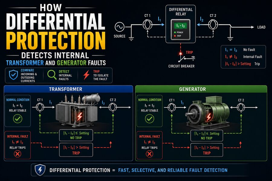
Differential protection works around a simple principle:
What enters a protected zone should approximately equal what leaves it.
If the electrical currents entering and leaving a transformer or generator are properly measured and compared, they should balance during normal operation and during many faults located outside the protected equipment.
But if a fault occurs inside the protected zone, some current flows into the fault instead of continuing through the equipment. The measured currents no longer balance.
A protective relay detects this difference—called differential current—and can rapidly trip the relevant circuit breakers. ⚡🛡️
Although the basic concept is simple, real differential protection systems must compensate for transformer ratios, phase shifts, current-transformer errors, generator operating conditions, magnetizing inrush, saturation, and many other practical effects.
🔍 What Is Differential Protection?
Differential protection is a unit protection scheme, meaning it protects a clearly defined section, or zone, of the power system.
For a transformer, that zone may extend between current transformers installed on the high-voltage and low-voltage sides.
For a generator, it may cover the stator winding between current transformers located at the terminals and neutral end.
The relay receives current measurements from both boundaries.
Under healthy conditions:
Current entering ≈ Current leaving
Therefore:
Differential current ≈ 0
If an internal fault occurs:
Current entering ≠ Current leaving
and the differential relay may issue a trip command.
This makes differential protection highly selective because it is designed to respond primarily to faults inside its own protected zone. 🎯
🧭 The Protected Zone
Understanding the protection zone is essential.
Imagine a transformer with current transformers, or CTs, installed on each side.
Conceptually:
Power system → CT → Transformer → CT → Power system
The region between the CT locations is the transformer differential protection zone.
If a short circuit occurs inside this region, differential protection should operate.
If a fault occurs outside the region—such as on a transmission line beyond one of the CTs—the currents measured at the boundaries should ideally remain balanced, so the transformer differential relay should remain stable.
This selective behavior allows another protection system to clear the external fault. 🛡️
🔌 Current Transformers Provide the Measurements
Protection relays usually cannot directly measure thousands of amperes flowing through large generators or power transformers.
Instead, they use current transformers.
A CT produces a much smaller secondary current proportional to the primary current.
For example, a CT rated:
1000:1
could conceptually transform 1000 A of primary current into approximately 1 A at its secondary, depending on the CT standard and design.
The relay receives these reduced current signals and compares them.
Modern numerical relays digitize the CT inputs and perform the differential calculations using signal-processing algorithms.
➖ The Differential Current Principle
Consider a simple device with current I₁ entering and I₂ leaving.
For normal operation:
I₁ ≈ I₂
The relay can calculate a differential quantity such as:
I_diff = |I₁ - I₂|
If:
I₁ = 500 A
and:
I₂ = 498 A
the small difference may simply result from measurement error.
But suppose an internal fault causes:
I₁ = 5,000 A
while only:
I₂ = 500 A
is measured leaving the protected zone.
Now the difference is enormous.
The relay recognizes that current is disappearing somewhere inside the zone—physically, it is flowing through an unintended fault path.
The relay can then trip the breakers. ⚡
🔥 What Happens During an Internal Fault?
An internal transformer fault may involve:
- Winding-to-ground faults
- Winding-to-winding faults
- Phase-to-phase faults
- Interturn faults
- Bushing-related faults within the protected zone
A generator may experience:
- Stator phase-to-phase faults
- Stator phase-to-ground faults
- Winding insulation failures
When such a fault develops, current can flow from the electrical system toward the fault from one or multiple directions.
Because this current does not pass normally through the protected equipment from one boundary to the other, the CT measurements become unbalanced.
This is precisely the condition differential protection is designed to recognize.
⚡ Why Differential Protection Is Fast
Many backup protection systems intentionally include time delays.
For example, an overcurrent relay may wait before tripping so that another downstream relay has an opportunity to clear a fault first.
Differential protection usually does not need as much coordination delay because its zone is clearly defined by the CT locations.
If the relay is confident that the fault is inside the protected zone, it can operate very quickly.
Fast clearing is critical because fault energy can be enormous.
The thermal energy released during a fault increases with factors related to current magnitude and duration.
Therefore, reducing clearing time can significantly reduce damage. ⏱️
⚖️ Why a Relay Cannot Trip on Every Small Difference
In a perfect system:
I₁ = I₂
during normal operation.
Real systems are not perfect.
Small differential currents can appear because of:
- CT ratio errors
- CT phase errors
- Measurement tolerances
- Wiring differences
- Transformer tap changes
- CT saturation
- Relay measurement error
If the relay tripped whenever it saw even a tiny mismatch, nuisance trips would be common.
Therefore, practical differential protection uses a percentage differential or biased differential characteristic.
📈 Percentage or Biased Differential Protection
A biased differential relay compares not only differential current but also the magnitude of current flowing through the equipment.
A simplified restraint quantity might be:
I_restraint ≈ (|I₁| + |I₂|) / 2
The relay then requires the differential current to exceed a threshold related to the restraint current.
As through-current increases, the relay may require a larger differential current before operating.
This creates greater stability during heavy external faults, when CT measurement errors or saturation are most likely.
The concept is:
Small through-current → high sensitivity
Large through-current → stronger restraint
This balance allows the relay to detect genuine internal faults while resisting false operation. 🛡️
📊 Understanding the Operating Characteristic
A percentage differential relay is often visualized on a graph.
One axis represents:
Restraint current
The other represents:
Differential current
Below the relay’s characteristic:
Do not trip
Above it:
Trip
Modern relays may use multiple slopes.
For example:
- A low-current region with high sensitivity
- A moderate slope for normal CT mismatch
- A steeper region for very large through-fault currents
This improves security under severe system conditions.
🏭 Transformer Differential Protection Is More Complicated
Applying differential protection to a generator is conceptually straightforward because the current entering and leaving the same winding can often be compared directly.
Transformers introduce additional complications.
A transformer intentionally changes:
- Voltage
- Current magnitude
- Sometimes phase relationship
Suppose a transformer reduces voltage from high voltage to low voltage.
Because power is approximately conserved apart from losses:
Lower voltage generally means higher current.
Therefore, the raw CT measurements on the two sides cannot simply be subtracted without compensation.
🔄 Transformer Ratio Compensation
Imagine a transformer carrying approximately:
100 A
on its high-voltage side and:
1,000 A
on its low-voltage side.
These currents are perfectly normal if the turns ratio is approximately 10:1.
A naive differential relay would see:
100 A vs. 1,000 A
and conclude that something was terribly wrong.
Instead, the relay scales the current measurements to a common reference.
After compensation, the values should correspond closely during healthy operation.
Modern numerical relays usually perform this ratio compensation internally. 🧠
🔺 Transformer Phase-Shift Compensation
Three-phase transformers can also introduce phase shifts depending on winding connections.
For example, delta-wye transformer configurations can produce a phase displacement between currents on the two sides.
The differential relay must account for this.
Historically, engineers could use specific CT connection arrangements to compensate for transformer phase shift.
Modern digital relays can frequently perform the necessary phase compensation mathematically.
Without proper compensation, normal load current could appear as differential current and cause false operation.
🔧 Tap Changers Create Additional Mismatch
Many power transformers contain an on-load tap changer.
The tap changer adjusts the effective turns ratio to regulate voltage.
As the tap position changes, the expected current relationship between the transformer sides changes slightly.
This produces normal mismatch in a differential comparison.
Protection settings therefore include sufficient restraint to remain stable throughout the transformer’s permitted tap range while still detecting genuine faults.
This is another reason percentage differential protection is preferred over a simple fixed current-difference threshold.
🧲 The Magnetizing Inrush Problem
One of the most famous challenges in transformer differential protection is magnetizing inrush current.
When an unloaded transformer is energized, it can briefly draw a very large current.
The magnitude may be several times rated current.
From the relay’s perspective, this can look suspicious.
Current enters the transformer, but there may be very little corresponding load current leaving the secondary.
That creates a large apparent differential current.
Yet nothing is necessarily wrong. ⚠️
If the relay treated every large differential current as an internal fault, it might trip every time the transformer was energized.
🌊 Harmonic Restraint and Inrush Detection
Transformer inrush current often contains characteristic waveform distortion and substantial harmonic content, traditionally including a significant second harmonic component.
Differential relays can analyze the current waveform.
If the relay identifies characteristics associated with magnetizing inrush, it can restrain or block the differential trip function temporarily.
Modern numerical relays may use more sophisticated waveform-based algorithms in addition to traditional harmonic restraint.
The goal is to distinguish:
Transformer energization → do not trip
from:
Internal winding fault → trip quickly
This discrimination is one of the most important features of transformer differential protection. 🧲⚡
🌡️ Overexcitation and Fifth Harmonic
Transformers can also experience overexcitation, sometimes called overfluxing.
This can occur when the ratio of voltage to frequency becomes excessive.
The transformer core moves deeper into magnetic saturation, causing increased magnetizing current and heating.
Historically, certain differential protection schemes have used harmonic characteristics, including fifth-harmonic behavior, to help distinguish overexcitation from internal faults.
Modern protection systems may coordinate differential elements with dedicated volts-per-hertz protection for this condition.
⚠️ Current Transformer Saturation
CT saturation is another major challenge.
During a severe external fault, huge current may pass through the protected transformer or generator.
Ideally, CTs on both sides would reproduce that current accurately.
But if one CT saturates, its secondary waveform may become distorted and smaller than expected.
The relay can then see a false differential current even though the actual fault lies outside the protected zone.
This is precisely when biased restraint becomes important.
Modern relays may also use CT-saturation detection algorithms to improve stability during external faults. 🛡️
🌀 External Fault Example
Imagine a transformer operating normally when a short circuit occurs on a transmission line beyond its low-voltage-side CT.
A very large fault current flows through the transformer toward the external fault.
The high-side CT measures the large incoming current.
The low-side CT measures the corresponding outgoing current.
After ratio and phase compensation:
I_high ≈ I_low
Therefore:
I_diff ≈ 0
The transformer differential relay remains restrained.
A line protection relay clears the external fault instead.
This is the selectivity that makes differential protection so useful.
🔥 Internal Fault Example
Now imagine a phase-to-ground fault develops inside the transformer winding between the CT locations.
Large current enters the protected zone and flows into the fault.
The currents no longer correspond properly at the two boundaries.
The differential relay sees:
I_diff > operating threshold
and determines that the fault is internal.
It sends trip commands to the appropriate breakers, isolating the transformer from every source that can feed the fault.
In large power transformers, multiple breakers may need to trip because current could reach the fault from more than one side.
⚙️ Generator Differential Protection
Large synchronous generators also commonly use differential protection.
The stator windings are particularly important because internal faults can damage copper conductors, insulation, and the laminated iron core.
For each phase, CTs may be installed at:
- Generator terminal end
- Generator neutral end
During normal operation, the same phase current flows into one end of the stator winding and out the other.
The relay compares those currents.
If a fault occurs inside the winding section between the CTs, the balance changes.
The protection trips the generator. ⚡
🔌 Generator Stator Phase Faults
Suppose phase A of a generator develops an internal phase-to-phase fault with phase B.
Very large current can circulate through the fault.
The differential elements associated with the affected phases detect significant imbalance.
Because the fault lies within the stator differential zone, rapid isolation is required.
Generator protection may command actions including:
- Opening the generator breaker
- Removing field excitation
- Tripping the prime mover
- Initiating other shutdown functions
The exact trip sequence depends on plant design.
🌍 Ground Faults Near the Generator Neutral
One limitation of some generator phase differential schemes is sensitivity to ground faults very close to the neutral point.
Near the neutral, the available fault voltage can be relatively small, so ground-fault current may also be small depending on grounding configuration.
Dedicated stator ground-fault protection is therefore commonly used alongside phase differential protection.
Generator protection is rarely based on one relay function alone.
A comprehensive scheme may include protection for:
- Differential faults
- Stator ground faults
- Rotor ground faults
- Loss of excitation
- Reverse power
- Negative sequence
- Overvoltage
- Overfrequency and underfrequency
- Overexcitation
🛡️
🧩 Restricted Earth Fault Protection
Transformers may also use Restricted Earth Fault, or REF, protection.
REF is a sensitive differential-style scheme specifically intended for ground faults within a defined winding zone.
It compares currents from phase CTs and a neutral CT.
Because it focuses specifically on earth faults in a restricted area, it can often detect lower-magnitude ground faults than the main transformer differential element.
REF and overall transformer differential protection are therefore complementary.
⏱️ Why Internal Faults Must Be Cleared Quickly
Electrical fault currents produce multiple forms of damage.
🔥 Thermal Damage
High current produces intense resistive heating.
💥 Mechanical Forces
Fault currents create powerful electromagnetic forces capable of deforming transformer windings or generator conductors.
⚡ Arc Damage
Internal arcing can destroy insulation and vaporize conductive material.
🧯 Fire Risk
Transformer oil and surrounding equipment may become involved in severe failures.
The longer the fault remains energized, the greater the potential damage.
Rapid differential protection can turn a serious failure into a repairable incident rather than catastrophic equipment destruction.
🛑 Differential Protection Usually Trips Without Intentional Delay
Because the scheme is selective, internal differential operation often results in rapid breaker tripping.
There may still be small processing and breaker-operating times, but intentional coordination delays are generally minimized.
Typical sequence:
Fault begins
➡️
CTs detect current imbalance
➡️
Relay calculates differential quantity
➡️
Relay confirms operating criteria
➡️
Trip signal issued
➡️
Circuit breakers open
All of this can occur extremely quickly. ⚡⏱️
🧠 Numerical Differential Relays
Modern protection relays are essentially specialized industrial computers.
They continuously sample current waveforms and apply digital algorithms.
A modern differential relay can perform:
- Ratio compensation
- Phase-shift compensation
- Harmonic analysis
- Bias calculations
- CT saturation detection
- Disturbance recording
- Event logging
- Self-diagnostics
It can also communicate with substation automation systems.
This allows engineers to retrieve detailed information after a fault.
📊 Event Records Help Engineers Understand Faults
When a relay trips, it may store:
- Current waveforms
- Voltage waveforms
- Differential current
- Restraint current
- Trip timing
- Digital input states
- Breaker status
Protection engineers can examine these oscillographic records after an incident.
This helps determine:
- Where the fault occurred
- Whether the relay operated correctly
- How severe the fault was
- How quickly breakers cleared it
Such records are extremely valuable for power-system analysis. 🔍
🧪 Protection Testing
Differential protection must be carefully tested before equipment enters service.
Testing can verify:
- CT polarity
- CT ratio
- Wiring
- Relay settings
- Transformer vector compensation
- Trip circuits
- Breaker operation
Incorrect CT polarity is particularly dangerous.
If one CT is connected backwards, normal current may appear as a large differential quantity.
Commissioning engineers therefore verify the entire current circuit and relay behavior before energization.
🔁 CT Polarity Matters
Current transformers have defined polarity markings.
The protection system depends on those polarities so currents can be mathematically compared in the correct direction.
If both CT measurements represent current entering the protected zone, the relay’s internal logic must account for the appropriate signs.
A wiring mistake can transform:
I₁ - I₂ ≈ 0
into something resembling:
I₁ + I₂
during normal operation.
That could produce an immediate false trip.
Correct polarity is therefore fundamental.
🧠 Kirchhoff’s Current Law Behind the Concept
The underlying electrical principle is closely related to Kirchhoff’s Current Law.
KCL states that the algebraic sum of currents entering and leaving a node or enclosed region must be zero when charge is not accumulating.
Differential protection effectively applies this idea to a protected piece of equipment.
Under normal operation:
Current entering the zone ≈ current leaving the zone.
During an internal fault:
Some current leaves the intended circuit through the fault path.
The measured imbalance reveals the problem.
This is why differential protection can be thought of as an electrical accounting system. 📒⚡
🆚 Differential Protection vs. Overcurrent Protection
Overcurrent protection asks:
“Is the current too large?”
Differential protection asks:
“Do the currents entering and leaving this specific zone balance?”
This distinction matters.
A transformer can carry enormous current during an external fault without being internally damaged.
An overcurrent relay sees the large current.
A differential relay sees balanced through-current and remains stable.
Conversely, some internal faults may produce differential current that allows fast selective detection even when coordination with normal load current would make simple overcurrent protection less effective.
The two protection methods often work together.
🛡️ Main Protection and Backup Protection
Differential protection is commonly used as primary protection for important transformers and generators.
But engineers do not rely on it alone.
Backup protection may include:
- Overcurrent
- Ground fault
- Distance protection
- Breaker failure protection
- Thermal protection
- Mechanical transformer protection
If the differential relay or breaker fails, another protection layer should eventually isolate the problem.
Power-system protection is built around redundancy because equipment failures themselves cannot be assumed away.
🏭 Transformer Mechanical Protection
Large oil-filled transformers may also contain mechanical protection devices such as Buchholz relays or sudden-pressure detection, depending on transformer construction.
These devices can detect physical effects associated with internal faults, such as gas generation or rapid pressure changes.
Electrical differential protection and mechanical protection therefore provide different types of evidence about internal transformer problems.
Using multiple independent principles can improve overall protection coverage.
🎯 Sensitivity vs. Security
Every protection engineer faces an important balance.
A relay should be sensitive enough to detect genuine faults.
But it must also be secure enough to avoid tripping during normal events such as:
- Load changes
- Transformer energization
- External short circuits
- CT errors
- Tap changes
Too insensitive:
Real faults may go undetected.
Too sensitive:
Healthy equipment may trip unnecessarily.
Percentage restraint, harmonic detection, compensation, and careful settings help achieve the right balance. ⚖️
🧩 A Simple Analogy
Imagine a secure warehouse with two gates.
Every box entering through Gate A should eventually leave through Gate B.
If:
100 boxes enter
and:
100 boxes leave
everything balances.
But if:
100 boxes enter
and only:
70 boxes leave
then 30 boxes must have gone somewhere inside the warehouse.
A differential relay performs the same kind of accounting—but with electrical current instead of boxes. 📦⚡
A large unexplained mismatch suggests that current is flowing through an internal fault.
✅ Conclusion
Differential protection detects internal transformer and generator faults by continuously comparing the electrical currents at the boundaries of a protected zone. ⚡🛡️
During normal operation, the currents entering and leaving the equipment should correspond closely after appropriate compensation.
During an external fault, enormous current may flow through the equipment, but it still enters and leaves the protected zone in approximately balanced amounts.
During an internal fault, however, some current flows into the fault path inside the transformer or generator. The balance is broken.
The relay detects this differential current and can quickly command circuit breakers to isolate the equipment.
Real systems require much more sophistication than a simple subtraction. Transformer protection must compensate for turns ratio, vector-group phase shift, tap position, magnetizing inrush, CT saturation, and measurement errors. Generator protection must account for stator configuration, grounding, CT performance, and complementary protection functions.
Percentage restraint allows relays to remain sensitive to internal faults while stable during high external through-current. Harmonic and waveform analysis help prevent transformer energization from being mistaken for a fault, while modern numerical relays provide sophisticated signal processing and detailed event records.
The central idea, however, remains elegantly simple:
If all current entering a protected piece of equipment does not come back out through the expected paths, something may be wrong inside it. ⚡
By detecting that imbalance within milliseconds, differential protection can prevent severe faults from developing into catastrophic transformer or generator failures—making it one of the most important protection principles in modern electrical power systems. 🏭🔌🛡️