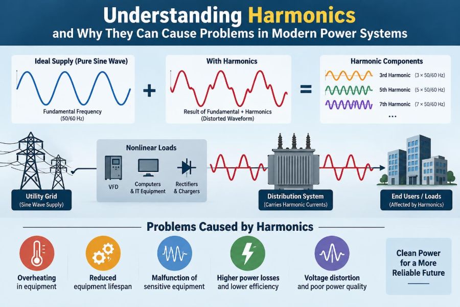

A facility manager notices that a transformer runs unexpectedly hot, even though the building’s measured load appears comfortably below its nameplate rating. Elsewhere, lights flicker when a bank of computers starts up, circuit breakers trip without an obvious fault, and a backup generator sounds strained while serving what seems like an ordinary office load.
These problems can share a less visible cause: the current and voltage are no longer smooth sine waves. Modern electrical systems increasingly supply electronic equipment that draws power in short pulses rather than in the even, sinusoidal pattern assumed by many traditional design practices.
That distortion is known as harmonic distortion. It does not mean that every electronic load is dangerous or that a distorted waveform automatically signals a failure. But when harmonics are large enough, or interact badly with system impedance and capacitors, they can create overheating, nuisance operation, inaccurate measurements, and poor equipment performance.
Understanding harmonics helps engineers diagnose issues that conventional RMS measurements can miss. It also helps designers make sound choices about transformers, conductors, capacitor banks, filters, and sensitive electronic loads.
🎵 The ideal waveform: a single sine wave
In an ideal AC power system, voltage and current vary smoothly and repetitively as sine waves. In a 50 Hz system, the fundamental waveform completes 50 cycles every second; in a 60 Hz system, it completes 60.
This fundamental frequency is the waveform that rotating generators, motors, transformers, and much of the traditional power system were designed around. A purely sinusoidal current at the same frequency as the voltage is straightforward to analyze and produces predictable losses and magnetic behavior.
Real systems are never perfectly ideal. Small waveform deviations occur naturally, but the concern rises when additional frequency components become large enough to affect equipment operation or power quality.
🧩 What a harmonic actually is
A harmonic is a sinusoidal component whose frequency is an integer multiple of the fundamental frequency. In a 60 Hz system, the third harmonic is 180 Hz, the fifth is 300 Hz, and the seventh is 420 Hz. In a 50 Hz system, those same orders occur at 150 Hz, 250 Hz, and 350 Hz.
A distorted waveform can be represented as the fundamental sine wave plus one or more harmonic sine waves. This is not just a mathematical convenience: each harmonic order behaves differently in transformers, cables, machines, and three-phase connections.
Think of a musical note played alongside its overtones. The note is still present, but the added frequencies change its character. In power systems, the result is a waveform with flattened peaks, sharp edges, notches, or pulse-like current draw.
📏 Harmonic order and frequency
Harmonics are normally identified by order rather than only by frequency. The fifth harmonic means five times the fundamental frequency, regardless of whether the local grid operates at 50 Hz or 60 Hz.
The order matters because it helps predict direction of rotation, neutral behavior, resonant conditions, and likely equipment effects. Lower-order harmonics often receive the most attention because they are commonly significant and can interact strongly with network components.
| Harmonic order | Frequency on 50 Hz supply | Frequency on 60 Hz supply | Typical engineering concern |
|---|---|---|---|
| 3rd | 150 Hz | 180 Hz | Neutral current and transformer heating |
| 5th | 250 Hz | 300 Hz | Negative-sequence effects in motors |
| 7th | 350 Hz | 420 Hz | Motor heating and waveform distortion |
| 11th and 13th | 550 / 650 Hz | 660 / 780 Hz | Converter-related distortion and losses |
Not every harmonic order occurs in every installation. The spectrum depends on the loads, their control method, source strength, and the network’s frequency response.
📊 Total harmonic distortion in plain language
Total harmonic distortion, usually abbreviated THD, expresses how much harmonic content exists relative to the fundamental component. Voltage THD describes distortion of the voltage waveform; current THD describes distortion of the current waveform.
A current waveform can have high THD at a device while the supply voltage remains fairly sinusoidal, particularly when the supply is electrically stiff. Conversely, harmonic current flowing through source impedance creates harmonic voltage drops, which can raise voltage distortion for other customers or loads.
THD is useful for comparison, but it is not a complete diagnosis. Two waveforms with equal THD can have different harmonic orders and therefore very different practical consequences.
🔍 Current distortion versus voltage distortion
Nonlinear equipment usually creates harmonic current. The electrical network then converts some of that current distortion into harmonic voltage through its impedance.
The relationship is conceptually simple: harmonic voltage is related to harmonic current multiplied by the network impedance at that frequency. A weak source, long cable run, overloaded transformer, or resonant network can therefore experience more voltage distortion from the same nonlinear load than a strong utility connection.
This distinction matters in troubleshooting. Blaming a sensitive device for “bad voltage” may miss the actual source: another load injecting harmonic current upstream or nearby.
🔌 Why nonlinear loads change the current shape
A linear load, such as an uncomplicated resistance or a traditional induction motor operating directly from the supply, tends to draw current with a waveform that follows the applied voltage. The current may lead or lag because of capacitance or inductance, but it remains broadly sinusoidal.
A nonlinear load does not draw current in direct proportion to instantaneous voltage. Its impedance effectively changes through the AC cycle. Rectifiers, switching devices, and energy-storage capacitors often draw current only near voltage peaks, creating narrow pulses rich in harmonics.
The equipment may still consume useful real power efficiently. High efficiency and low harmonic distortion are related but separate properties.
💻 Common sources in modern facilities
Electronic power conversion is now widespread in commercial, industrial, and residential systems. Many devices contain rectifiers, switched-mode power supplies, or variable-speed controls that can contribute harmonic current.
- Computer, server, and telecommunications power supplies
- LED lighting drivers and electronic ballasts
- Variable-frequency drives for pumps, fans, and conveyors
- Uninterruptible power systems and battery chargers
- Welders, arc furnaces, and certain industrial process equipment
- Solar inverters, electric-vehicle chargers, and other power-electronic interfaces
This list should not be read as a list of defective technologies. Well-designed equipment often includes measures to limit emissions. The issue is the combined effect of many devices and their interaction with a particular electrical distribution system.
🏢 Why aggregation can surprise designers
A single laptop charger may create little system-level concern. Hundreds of similar chargers, lighting drivers, and IT power supplies on the same distribution transformer can produce a material harmonic current profile.
Harmonics do not always add arithmetically. Their phase angles, operating times, and spectra differ, so some components partly cancel while others reinforce. That makes assumptions based only on connected kW unreliable.
A credible assessment considers load diversity, equipment types, expected simultaneous operation, and the impedance between those loads and the supply point.
🔺 The special behavior of triplen harmonics
The third harmonic and its odd multiples—ninth, fifteenth, and so on—are called triplen harmonics. In a balanced three-phase, four-wire system, these components are in phase on all three phases rather than being 120 degrees apart.
As a result, triplen currents add in the neutral conductor. The neutral can carry substantial current even when the fundamental phase currents are balanced and the expected fundamental neutral current is near zero.
This is one reason neutral conductors in buildings with concentrated electronic loads require deliberate design. A neutral should not automatically be assumed to carry less current than a phase conductor.
🔥 Transformer heating is more than load current
Transformers experience copper losses from current and core losses from magnetic flux. Harmonic currents increase RMS current and create additional eddy-current and stray-flux losses, which tend to rise more sharply at higher frequencies.
A transformer can therefore run hot despite a seemingly acceptable kW reading. The nameplate kVA rating alone may not tell the whole story when it serves substantial nonlinear load.
Possible responses include selecting a transformer designed for harmonic-rich service, derating an existing unit based on a qualified assessment, reducing distortion at the source, or redistributing nonlinear loads. The correct option depends on the actual harmonic spectrum and thermal condition.
🧵 Cables, busways, and the skin-effect question
Conductors have resistance, and harmonic current creates additional I²R heating. At higher frequencies, current tends to concentrate closer to a conductor’s surface, an effect called skin effect. Nearby conductors can also influence current distribution through proximity effect.
At the lower harmonic orders common in building systems, these effects may be modest for some conductor types and sizes, but they become increasingly relevant in large conductors, busbars, cable trays, and high-frequency-rich installations.
The practical lesson is not to oversize every cable indiscriminately. It is to include harmonic current, neutral loading, installation conditions, and applicable code requirements in the conductor design rather than relying only on fundamental-load calculations.
⚙️ Motors face negative-sequence harmonics
Three-phase motors are sensitive to the sequence of the applied fields. The fifth harmonic is a negative-sequence component: it produces a rotating magnetic field opposite to the normal fundamental field.
That opposing field can create additional rotor heating and torque pulsations. The seventh harmonic is positive sequence, but it can still contribute to losses and torque ripple. The practical outcome can be increased temperature, vibration, noise, or reduced performance margin.
Effects vary with motor design, loading, supply stiffness, and the harmonic spectrum. A motor problem should be investigated with measurements rather than attributed to harmonics solely because a drive or electronic load exists nearby.
🛡️ Capacitor banks and resonance risk
Capacitor banks are commonly installed for power-factor correction because they supply reactive power locally. However, capacitors and system inductance can form a resonant circuit at certain frequencies.
If a resonant frequency lies near a harmonic generated in the system, harmonic current or voltage can be amplified. This may overload capacitors, blow fuses, create excessive voltage distortion, or cause repeated bank failures.
Capacitors are not inherently incompatible with nonlinear loads. They must be engineered with the network in mind. Detuned reactor-capacitor assemblies are frequently used to shift the resonant point away from dominant harmonic frequencies.
🌀 Series and parallel resonance are different
Series resonance produces a low impedance path at a particular frequency, potentially allowing high harmonic current to circulate. Parallel resonance produces high impedance at a particular frequency, potentially causing harmonic voltage amplification at a bus.
The exact behavior depends on the source inductance, transformer impedance, cable characteristics, capacitor size, and operating configuration. Adding or switching a capacitor bank can change the system response significantly.
Because resonance is a network property, a solution that works on one site should not be copied blindly to another. Studies and measurements are especially valuable before modifying large capacitor installations.
📟 Sensitive electronics can misbehave before they fail
Electronic controls usually tolerate some distortion, but their behavior depends on design and operating conditions. Distorted voltage can affect zero-crossing detection, timing circuits, control algorithms, and power-supply input stages.
Symptoms can include communication errors, unexplained restarts, unstable controls, flicker, or protective alarms. Such symptoms also have many non-harmonic causes, including voltage sags, grounding problems, electromagnetic interference, loose connections, and software faults.
A disciplined investigation separates correlation from cause. Capturing waveform data at the time of the event is far more useful than relying on a single averaged meter reading.
⚖️ Power factor is not the same as harmonic performance
Traditional power factor describes the relationship between real power and apparent power. With sinusoidal waveforms, it is closely linked to displacement between voltage and current. With distorted current, the picture is broader.
Displacement power factor describes the phase shift of the fundamental components. True power factor also reflects waveform distortion. A load can have a near-unity fundamental displacement power factor while still having reduced true power factor due to harmonic current.
This distinction prevents a common mistake: assuming that corrected power factor automatically means low harmonic distortion. Capacitors may improve displacement power factor while worsening a resonance problem if they are not properly designed.
🧮 RMS readings can hide waveform details
RMS voltage and current are valuable because they relate to heating and power delivery. Yet an RMS value compresses a complex waveform into one number. It does not reveal whether current is sinusoidal, peaked, notched, or rich in a particular harmonic order.
A true-RMS instrument is generally preferable for distorted waveforms, but even it cannot provide a harmonic spectrum unless it has power-quality analysis capability. A basic clamp meter may show that current is high without showing why.
For harmonic work, measurements commonly include RMS values, voltage and current THD, individual harmonic magnitudes, real and apparent power, crest factor, demand trend, and event waveforms.
📈 Crest factor offers a useful clue
Crest factor is the ratio of a waveform’s peak value to its RMS value. A sine wave has a familiar fixed crest factor, while pulsed current from rectifier-capacitor inputs can have a much higher value.
A high crest factor can reveal that current arrives in short peaks rather than being distributed smoothly through the cycle. These peaks place particular stress on components and can challenge meters or protective devices not intended for nonsinusoidal conditions.
Crest factor is a clue, not a verdict. It should be interpreted alongside the harmonic spectrum and equipment operating data.
🧭 Where measurements should be taken
The point of measurement determines the question being answered. Measurements at a nonlinear load show what that equipment draws; measurements at a panel show the combined effect of several loads; measurements at the point of common coupling indicate what reaches the shared supply.
For a nuisance trip, measure near the affected protective device and, where practical, upstream for comparison. For transformer overheating, measure secondary current on all phases and neutral, then assess voltage distortion at the transformer terminals.
Logging over representative operating periods matters. A five-minute snapshot taken during light load can miss a drive sequence, charging cycle, shift change, or lighting schedule that creates the actual problem.
🧰 A practical harmonic investigation sequence
- Define the symptom precisely: overheating, trips, capacitor failures, flicker, process errors, or a utility compliance concern.
- Identify recent changes, including new drives, LED retrofits, UPS installations, chargers, or capacitor-bank modifications.
- Review the one-line diagram, transformer data, conductor arrangement, grounding system, and major load locations.
- Measure voltage and current simultaneously at relevant points over a representative interval.
- Examine individual harmonic orders, neutral current, loading, and switching events rather than relying only on THD.
- Test a mitigation proposal against the network before installation, then verify performance afterward.
This sequence reduces the risk of treating a symptom while leaving the underlying interaction unchanged.
📐 Standards guide limits, not automatic diagnoses
Power-quality standards and utility requirements provide useful frameworks for evaluating harmonic voltage and current. They typically distinguish between distortion at a shared supply interface and distortion internal to a facility.
Limits are not universal pass/fail labels for every piece of equipment. Permissible levels depend on system voltage, the strength of the supply, load size, and where the measurement is made. A current limit at a point of common coupling is not necessarily a design limit at an individual branch circuit.
Use the applicable local rules, contract requirements, equipment instructions, and recognized engineering guidance. When consequences are significant, a qualified power-quality engineer should interpret the results in the actual system context.
🔧 Source-side mitigation: reduce emitted harmonics
The most direct strategy is to reduce harmonic current where it originates. Modern drives and power supplies may offer lower-distortion input arrangements, line reactors, DC-link chokes, multi-pulse rectification, or active front ends.
Line reactors and chokes add inductance that broadens current draw and limits certain harmonic components. They are often practical, but their effectiveness depends on the converter and installation; they are not a universal cure.
Specifying low-emission equipment early is often easier than correcting a crowded electrical room after problems emerge. Procurement specifications should address expected power quality, not just kW, efficiency, and purchase price.
🧹 Passive filters: targeted but system-dependent
A passive harmonic filter uses combinations of inductors, capacitors, and sometimes resistors to provide a low-impedance path for selected harmonic frequencies. Tuned filters can be effective for a known, relatively stable harmonic spectrum.
They can also provide reactive power support, which may be helpful in some industrial installations. However, their performance changes with system impedance and loading, and poor coordination can introduce unwanted resonances.
Passive filters therefore require careful tuning, protection, switching considerations, and periodic inspection. Component aging and future load changes can alter the original design assumptions.
🤖 Active filters adapt to changing loads
An active harmonic filter uses power electronics and control algorithms to inject compensating current. Rather than absorbing a fixed set of frequencies, it can respond to a changing harmonic spectrum within its rating and control bandwidth.
This flexibility can suit facilities with variable IT loads, changing production lines, or multiple harmonic sources. Active filters may also help with reactive power and load balancing functions, depending on the equipment.
They are not magic boxes. Correct current-transformer placement, rating, installation location, source impedance, and coordination with capacitors still determine whether the result is effective and stable.
🏗️ Distribution design can prevent future trouble
Harmonic resilience begins during design. Segregating large nonlinear loads, locating sensitive equipment on suitable distribution paths, allowing space for filtering, and selecting appropriately rated transformers can prevent expensive retrofits.
Neutral sizing, busbar configuration, transformer thermal capability, and capacitor-bank design deserve early attention where electronic loads will dominate. So does the available fault level: a stiffer source generally experiences less voltage distortion for the same injected harmonic current.
Good design does not require predicting every future device. It requires leaving practical margins and avoiding assumptions that all loads will remain linear.
🚫 Common mistakes in harmonic troubleshooting
- Looking only at kW: thermal stress and distortion are often tied to current waveform and kVA, not real power alone.
- Using THD as the sole metric: individual harmonic orders and absolute current levels can matter more than one percentage.
- Adding capacitors without analysis: this can create or shift resonance rather than solve a power-factor issue.
- Ignoring the neutral: triplen harmonics can make it a critical thermal path.
- Replacing failed components repeatedly: recurring capacitor or transformer failures may signal a system interaction, not poor component quality.
- Measuring once: intermittent operating patterns often require time-based logging.
🧑🔧 Maintenance clues worth taking seriously
Repeated capacitor fuse operations, overheated neutral terminations, transformer temperature alarms, abnormal acoustic noise, and persistent breaker trips deserve investigation. None proves a harmonic problem by itself, but together they create a useful diagnostic pattern.
Thermal imaging can identify hot connections and overloaded conductors, while power-quality monitoring explains whether waveform-related current contributes to the heating. Both methods are more informative when compared with loading and operating schedules.
Maintenance teams should document changes in equipment populations. A lighting retrofit, a new charging area, or an expanded server room may change the electrical behavior of a facility even when its total energy consumption changes little.
🌐 Harmonics and distributed energy resources
Solar photovoltaic systems, battery storage, and electric-vehicle charging add valuable flexibility to modern grids, but they also introduce more inverter-based interfaces. Their harmonic behavior depends on converter design, controls, filters, operating point, and connection strength.
Many modern inverters are designed to meet applicable interconnection and power-quality requirements. Still, a cluster of devices on a weak feeder can behave differently from one device tested in isolation.
Planning should examine aggregate effects, especially where feeder impedance is high or where capacitor banks and other frequency-sensitive equipment are already present.
🧠 A balanced view of modern electronic loads
Electronic loads have enabled efficient motor control, compact computing, LED lighting, renewable integration, and precise industrial automation. Harmonics are not an argument for abandoning these technologies.
They are a design and operating consideration. The goal is to understand the waveform consequences of power conversion, quantify them at the relevant point in the system, and apply proportionate mitigation where needed.
Most installations do not need every available harmonic solution. A modest nonlinear load on a strong system may require nothing beyond sound standard design. Large, concentrated, or sensitive installations demand more analysis.
✅ The core principle: manage the waveform, not just the watts
Harmonics arise when nonlinear loads draw nonsinusoidal current. Those currents interact with the impedance of transformers, cables, capacitors, and the supply, producing effects that range from negligible to operationally significant.
The most reliable approach is systematic: identify the harmonic source, measure at the right locations and times, examine the individual spectrum and network response, then select a mitigation method suited to the actual mechanism.
Power systems remain reliable when engineers consider both how much power a load uses and how that load draws it.
Harmonics are easier to manage when they are treated as a measurable system behavior rather than a mysterious defect. Careful design, meaningful measurements, and targeted solutions protect equipment while preserving the benefits of modern power electronics. ⚡📊🔧