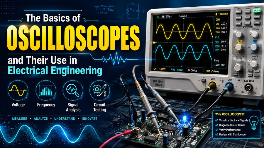

Oscilloscopes are among the most important instruments used in electrical and electronic engineering. They allow engineers, technicians, students, and researchers to see how electrical signals change over time. Instead of only telling you that a voltage exists, an oscilloscope can show its shape, amplitude, frequency, timing, noise, distortion, and other characteristics. ⚡📈
This makes oscilloscopes extremely useful when designing, testing, repairing, or troubleshooting electrical circuits.
A digital multimeter might tell you that a circuit has 5 volts, but an oscilloscope can reveal whether that 5-volt signal is stable, pulsing, noisy, distorted, or switching rapidly between different levels.
From simple laboratory experiments to advanced communication systems, embedded electronics, automotive circuits, power electronics, and industrial control systems, oscilloscopes provide engineers with a visual window into electrical behavior. 🔬
🔍 What Is an Oscilloscope?
An oscilloscope is an electronic test instrument that displays electrical signals as waveforms, usually with voltage shown vertically and time shown horizontally.
The display commonly has two main axes:
- Vertical axis: Voltage
- Horizontal axis: Time
As the electrical signal changes, the oscilloscope plots those changes across the screen.
For example, a sine wave from an AC signal might appear as a smooth repeating curve, while a digital signal might look like a series of square pulses.
This visual representation makes it much easier to understand what is happening inside a circuit.
⚡ Why Are Oscilloscopes Important?
Electrical signals are often dynamic.
Voltage can change millions or even billions of times per second in modern electronic circuits.
A standard voltmeter generally provides only a single numerical measurement at a particular moment or an averaged value.
An oscilloscope can reveal:
- 📈 Signal shape
- ⚡ Voltage level
- ⏱️ Timing
- 🔁 Frequency
- 📉 Signal distortion
- 🔊 Electrical noise
- ⏳ Pulse duration
- 🔄 Phase relationships
- 🚨 Glitches and abnormalities
This information is essential when testing whether a circuit behaves according to its design.
🧠 How Does an Oscilloscope Work?
At a basic level, an oscilloscope receives an electrical signal through a probe or cable.
The instrument then processes the signal and displays it as a waveform.
Modern digital oscilloscopes typically follow this process:
Input signal → Attenuation and amplification → Analog-to-digital conversion → Digital processing → Waveform display
The oscilloscope samples the incoming voltage at many points in time.
These samples are converted into digital values and reconstructed on the screen.
The faster and more accurately the oscilloscope samples the signal, the more faithfully it can display high-speed electrical activity.
🕰️ Analog vs. Digital Oscilloscopes
Oscilloscopes can broadly be divided into analog and digital types.
📺 Analog Oscilloscopes
Traditional analog oscilloscopes directly convert an input voltage into movement of an electron beam across a cathode-ray tube display.
The vertical position of the beam follows the voltage, while the horizontal movement represents time.
Analog oscilloscopes were once standard equipment in electronics laboratories.
Their advantages included:
- Smooth real-time waveform display
- Simple operation
- Immediate visual response
However, they provide limited storage and measurement capabilities compared with modern digital instruments.
💻 Digital Oscilloscopes
Digital oscilloscopes convert signals into digital data using an analog-to-digital converter.
This allows advanced features such as:
- Waveform storage
- Automatic measurements
- Mathematical analysis
- Frequency analysis
- Advanced triggering
- Data export
- Protocol decoding
Most modern engineering laboratories use digital oscilloscopes.
📐 Understanding the Oscilloscope Display
The display is usually divided into a grid called a graticule.
This grid helps engineers measure voltage and time.
Two important controls determine the scale.
📏 Volts per Division
The vertical scale is usually expressed as volts per division.
Suppose the oscilloscope is set to:
1 V/div
If the waveform rises by four vertical divisions, the voltage difference is:
4 × 1 V = 4 V
Changing the volts-per-division setting allows users to zoom in or out vertically.
⏱️ Seconds per Division
The horizontal scale is usually expressed as seconds per division.
For example:
1 ms/div
means every horizontal grid division represents one millisecond.
If one complete waveform cycle occupies five divisions:
5 × 1 ms = 5 ms
The waveform period is therefore 5 milliseconds.
🔁 Measuring Frequency
Frequency tells us how many times a repeating waveform completes one cycle per second.
It is measured in hertz (Hz).
Frequency and period are related by:
f = 1 / T
Where:
- f = frequency
- T = period
Suppose an oscilloscope shows a waveform with a period of:
T = 2 ms
Convert milliseconds to seconds:
2 ms = 0.002 seconds
Then:
f = 1 / 0.002
f = 500 Hz
Modern oscilloscopes can usually calculate frequency automatically.
🔋 Measuring Voltage With an Oscilloscope
Oscilloscopes can measure several voltage characteristics.
📈 Peak Voltage
Peak voltage is the maximum voltage reached by a waveform relative to a reference level.
↕️ Peak-to-Peak Voltage
Peak-to-peak voltage is the difference between the highest and lowest voltage points.
For example, if a waveform goes from:
+5 V to -5 V
then:
Vpp = 10 V
⚖️ RMS Voltage
RMS stands for root mean square.
For sinusoidal AC signals, RMS voltage relates to effective power delivery.
For an ideal sine wave:
Vrms = Vpeak / √2
Oscilloscopes may calculate RMS automatically for selected portions of a waveform.
🌊 Common Waveforms Seen on Oscilloscopes
Different circuits produce different waveform shapes.
🌐 Sine Wave
A sine wave is a smooth periodic waveform commonly associated with:
- AC power
- Oscillators
- Audio signals
- Radio systems
⬛ Square Wave
Square waves switch rapidly between high and low voltage levels.
They are common in:
- Digital electronics
- Clock signals
- Logic circuits
- Pulse-width modulation
🔺 Triangle Wave
A triangle wave rises and falls at a nearly constant rate.
It is often used in:
- Signal generators
- Modulation circuits
- Control systems
🪚 Sawtooth Wave
Sawtooth waves rise gradually and then drop sharply, or vice versa.
They may appear in:
- Timing circuits
- Sweep circuits
- Signal processing systems
💥 Pulses
Pulses are brief voltage events used extensively in digital and communication systems.
Oscilloscopes are especially useful for examining pulse width, rise time, and timing.
🎯 What Is Triggering?
One of the most important oscilloscope concepts is triggering.
Without proper triggering, a repeating waveform may appear unstable and move continuously across the screen.
A trigger tells the oscilloscope exactly when to begin displaying or capturing the signal.
For example, the oscilloscope might be instructed to trigger when the voltage crosses:
2 volts on a rising edge
This causes each display sweep to start at approximately the same point in the waveform.
The result is a stable image.
📉 Common Trigger Types
Modern oscilloscopes may support many trigger conditions.
Common examples include:
- Rising-edge trigger
- Falling-edge trigger
- Pulse-width trigger
- Video trigger
- Logic trigger
- Serial-data trigger
- Glitch trigger
Advanced triggering helps engineers capture unusual events that may occur only occasionally.
🔌 What Is an Oscilloscope Probe?
The probe connects the oscilloscope to the circuit being tested.
A typical passive probe includes:
- Probe tip
- Ground connection
- Coaxial cable
- Compensation adjustment
- Attenuation selector
Common probe settings include:
- 1×
- 10×
A 10× probe reduces the voltage presented to the oscilloscope by a factor of ten.
This provides several advantages, including reduced loading on many circuits and increased measurable voltage range.
However, the oscilloscope must be configured to match the probe’s attenuation factor.
⚠️ Probe Grounding and Safety
Oscilloscope grounding is extremely important.
On many bench oscilloscopes, the probe ground clip is electrically connected to protective earth.
Connecting that ground clip to the wrong point in a powered circuit can create a short circuit, damage equipment, or cause serious injury.
Special care is required when measuring:
- Mains electricity
- Switching power supplies
- High-voltage circuits
- Floating systems
- Motor drives
Suitable differential probes, isolation techniques, or properly rated equipment may be required.
Safety procedures should always match the voltage and circuit being measured. ⚡🛡️
📊 Important Oscilloscope Specifications
When selecting an oscilloscope, several specifications matter.
🚀 Bandwidth
Bandwidth describes the frequency range an oscilloscope can measure accurately.
For example, an oscilloscope with:
100 MHz bandwidth
is designed to handle signals up to approximately that frequency range within its specified performance limits.
Engineers generally choose bandwidth significantly higher than the fundamental frequency of the signal when accurate waveform shape is important.
Digital square waves contain high-frequency harmonics, so their required oscilloscope bandwidth can be much greater than their clock frequency alone suggests.
📡 Sample Rate
Sample rate tells us how many measurements the oscilloscope takes per second.
It may be specified as:
- MS/s — mega-samples per second
- GS/s — giga-samples per second
For example:
1 GS/s
means the oscilloscope can take up to one billion samples per second.
Higher sample rates help capture fast-changing signals accurately.
💾 Memory Depth
Memory depth determines how many samples can be stored in a waveform capture.
More memory allows the oscilloscope to record longer periods while maintaining high sample rates.
This is valuable when searching for rare signal problems.
🔢 Number of Channels
Oscilloscopes commonly have:
- 2 channels
- 4 channels
- More channels in advanced systems
Multiple channels allow engineers to compare several electrical signals simultaneously.
⚡ Rise Time
Rise time measures how quickly a signal transitions from a low voltage to a high voltage.
In digital electronics, this measurement is extremely important.
A signal may have a clock frequency of only a few megahertz but extremely fast edges.
Fast edges contain high-frequency components.
Oscilloscope bandwidth must therefore be sufficient to capture these transitions accurately.
🧮 Oscilloscope Measurements
Modern oscilloscopes can automatically calculate many measurements.
Common examples include:
- Frequency
- Period
- Peak voltage
- Peak-to-peak voltage
- RMS voltage
- Average voltage
- Rise time
- Fall time
- Pulse width
- Duty cycle
- Phase difference
These automatic measurements save time and reduce manual calculation.
However, engineers still need to understand how the measurements are obtained so they can recognize incorrect settings or misleading results.
📐 Duty Cycle
Duty cycle describes the percentage of time a periodic digital signal remains in its active state.
It can be calculated as:
Duty Cycle = Pulse ON Time / Total Period × 100%
Suppose a PWM signal is high for:
2 ms
during a total period of:
5 ms
Then:
Duty Cycle = 2 / 5 × 100%
Duty Cycle = 40%
Duty-cycle measurement is important in motor controls, switching power supplies, LED drivers, and digital systems.
🔄 Measuring Phase Difference
Oscilloscopes are useful for comparing signals.
Suppose two sine waves have the same frequency but their peaks occur at different times.
The phase difference can be determined from their horizontal separation.
Phase measurements are useful in:
- AC circuits
- Filters
- Amplifiers
- Power systems
- Control systems
Engineers may examine whether voltage leads or lags current, for example.
🔊 Detecting Electrical Noise
Real circuits rarely produce perfectly clean signals.
Electrical noise may come from:
- Switching circuits
- Power supplies
- Motors
- Radio-frequency interference
- Digital logic
- Ground loops
- Poor shielding
An oscilloscope makes noise visible.
Engineers can investigate:
- Random fluctuations
- Oscillations
- Voltage spikes
- Switching interference
- Grounding problems
Without an oscilloscope, many of these problems can be difficult to detect.
🐛 Troubleshooting Electronic Circuits
Oscilloscopes are especially valuable for diagnosing faulty electronics.
Imagine a circuit that is not working.
An engineer might follow the signal through each stage:
Input → Amplifier → Filter → Processor → Output
If the input is correct but the signal disappears after the amplifier, the fault may be located in or around that stage.
This allows engineers to locate problems efficiently.
🧠 Oscilloscopes in Digital Electronics
Digital systems depend heavily on precise timing.
Oscilloscopes can examine:
- Clock signals
- Logic levels
- Data pulses
- Reset signals
- Timing relationships
- Edge quality
- Noise
A digital signal that appears correct on a basic multimeter may actually contain small glitches capable of causing a processor to malfunction.
Oscilloscopes can reveal such problems.
🖥️ Serial Communication Analysis
Many modern digital oscilloscopes can decode communication protocols.
Examples include:
- UART
- I²C
- SPI
- CAN
- LIN
- USB in some systems
Instead of displaying only electrical pulses, the oscilloscope may interpret the signal and show transmitted data.
This is extremely useful for embedded-system development.
🚗 Oscilloscopes in Automotive Engineering
Modern vehicles contain complex electrical and electronic systems.
Automotive technicians and engineers use oscilloscopes to analyze:
- Crankshaft sensors
- Camshaft sensors
- Fuel injectors
- Ignition systems
- CAN bus signals
- Battery voltage
- Alternator ripple
- Motor-control signals
Waveform analysis can reveal problems that basic diagnostic codes may not identify.
⚙️ Oscilloscopes in Power Electronics
Power electronics involves controlling electrical energy using high-speed semiconductor switches.
Examples include:
- Inverters
- Motor drives
- DC-DC converters
- Battery chargers
- Switching power supplies
Oscilloscopes allow engineers to examine switching waveforms and timing.
Important measurements may include:
- Switching voltage
- Gate signals
- Current waveforms
- Ripple
- Switching frequency
- Dead time
Special high-voltage or differential probes may be required for safe measurements.
☀️ Renewable Energy Applications
Oscilloscopes also play a role in renewable-energy engineering.
They may be used when developing:
- Solar inverters
- Wind turbine converters
- Battery management systems
- Power conditioning equipment
- Electric vehicle chargers
Engineers can observe how switching electronics convert and regulate electrical energy.
📻 Oscilloscopes in Communication Engineering
Communication systems use rapidly changing electrical signals.
Oscilloscopes help engineers study:
- Modulated signals
- Pulse timing
- Signal distortion
- Noise
- Timing jitter
- Data integrity
High-speed communication systems often require specialized oscilloscopes with very high bandwidth and sample rates.
🎵 Audio Engineering Applications
Oscilloscopes can display audio waveforms produced by:
- Microphones
- Amplifiers
- Audio processors
- Signal generators
Engineers can look for clipping and distortion.
For example, if an amplifier is pushed beyond its maximum output range, a sine wave may become flattened at the top and bottom.
This is called clipping.
An oscilloscope makes clipping immediately visible.
🧪 Oscilloscopes in Engineering Education
Oscilloscopes are common in electrical engineering laboratories because they help students connect mathematical theory with real signals.
Students can directly observe concepts such as:
- AC voltage
- Frequency
- Phase
- RC charging curves
- Resonance
- Digital logic
- PWM
- Filters
- Amplifier behavior
Seeing these effects in real time can make abstract electrical concepts much easier to understand.
🔬 Oscilloscopes and Sensors
Many sensors produce electrical signals that change over time.
Examples include:
- Temperature sensors
- Pressure sensors
- Vibration sensors
- Optical sensors
- Magnetic sensors
- Microphones
An oscilloscope can help determine whether the sensor is producing the expected output.
This is valuable during sensor development and system integration.
📉 Capturing Transient Events
Some electrical problems happen only once or occur unpredictably.
Examples include:
- Voltage spikes
- Power interruptions
- Switching glitches
- Startup problems
Digital oscilloscopes can capture these short-lived transient events.
Engineers may configure the trigger so that the instrument stores the waveform when a specific abnormal event occurs.
This can make intermittent faults much easier to diagnose.
🔍 FFT and Frequency-Domain Analysis
Many digital oscilloscopes provide a mathematical tool called the Fast Fourier Transform, or FFT.
An ordinary oscilloscope display shows how voltage changes with time.
FFT analysis instead shows how signal energy is distributed across frequencies.
This can help identify:
- Harmonics
- Electrical noise
- Oscillation frequencies
- Switching interference
- Signal distortion
Although dedicated spectrum analyzers may provide more advanced frequency-domain capabilities, oscilloscope FFT functions are useful for many engineering tasks.
🧮 Mathematical Functions
Modern oscilloscopes can perform mathematical operations on channels.
For example:
Channel 1 − Channel 2
or:
Channel 1 × Channel 2
Multiplication can be useful in power analysis.
If one channel measures voltage and another measures current, multiplying them can help examine instantaneous electrical power.
🛠️ Common Mistakes When Using an Oscilloscope
Beginners often make several mistakes.
❌ Wrong Probe Setting
If the probe is set to 10× while the oscilloscope assumes 1×, the displayed voltage will be incorrect.
❌ Incorrect Ground Connection
Improper grounding can create dangerous shorts.
❌ Insufficient Bandwidth
A low-bandwidth oscilloscope may make fast signals appear slower or more rounded than they really are.
❌ Incorrect Trigger Settings
Poor triggering may make the waveform unstable.
❌ Excessive Sample Interval
Too few samples can produce inaccurate waveform reconstruction.
Understanding these limitations is important for reliable measurements.
🧰 How to Use an Oscilloscope: Basic Procedure
A simplified workflow for a safe low-voltage circuit might include:
- 🔌 Connect the correct probe.
- ⚙️ Match the probe attenuation setting.
- 🛡️ Identify a safe reference or ground point.
- 📍 Connect the probe to the test signal.
- 📏 Adjust volts per division.
- ⏱️ Adjust time per division.
- 🎯 Configure triggering.
- 📊 Observe the waveform.
- 🧮 Use measurement tools if needed.
- 💾 Save or document the waveform.
For higher-voltage or specialized systems, additional safety equipment and measurement techniques are required.
🆚 Oscilloscope vs. Multimeter
Both instruments are extremely useful, but they serve different purposes.
| Feature | Oscilloscope | Multimeter |
|---|---|---|
| Displays waveform | Yes | Usually no |
| Voltage measurement | Yes | Yes |
| Frequency measurement | Yes | Often |
| Resistance measurement | Usually no | Yes |
| Timing analysis | Excellent | Limited |
| Noise detection | Excellent | Limited |
| Circuit troubleshooting | Dynamic signals | General electrical measurements |
Electrical engineers often use both tools together.
🆚 Oscilloscope vs. Logic Analyzer
A logic analyzer is designed specifically for digital signals.
It can monitor many digital channels simultaneously and decode complex data patterns.
An oscilloscope typically has fewer channels but provides detailed analog information about signal voltage and shape.
For example:
A logic analyzer may tell you that a digital bit is high or low.
An oscilloscope can show whether that “high” level contains noise, ringing, or slow transitions.
In advanced digital debugging, engineers may use both instruments.
🛡️ Safety Considerations
Oscilloscopes can be used around dangerous voltages, so proper safety practices are essential.
Important precautions include:
- Use probes rated for the voltage being measured.
- Understand the oscilloscope’s grounding arrangement.
- Never exceed input voltage ratings.
- Use differential probes where appropriate.
- Keep hands away from exposed live conductors.
- Follow laboratory and electrical safety procedures.
- Avoid working on high-voltage circuits without appropriate training.
High-energy electrical systems can remain dangerous even after power is removed because capacitors may retain charge. ⚠️
🤖 The Future of Oscilloscopes
Oscilloscopes continue to become more advanced.
Modern instruments increasingly include:
- Automated signal analysis
- Artificial intelligence-assisted measurements
- Advanced protocol decoding
- Cloud connectivity
- Touchscreen interfaces
- Remote control
- Large memory systems
- High-resolution conversion
Some portable oscilloscopes can now connect directly to laptops or tablets.
Software-defined instruments are also becoming more common.
These advances make sophisticated waveform analysis more accessible.
❓ Frequently Asked Questions
What does an oscilloscope measure?
An oscilloscope primarily measures voltage changes over time. With appropriate probes and techniques, it can also help analyze current, frequency, phase, timing, and many other electrical characteristics.
Why use an oscilloscope instead of a multimeter?
A multimeter usually shows numerical values, while an oscilloscope displays the shape and timing of an electrical signal. This makes oscilloscopes better for analyzing dynamic or rapidly changing signals.
What is oscilloscope bandwidth?
Bandwidth indicates the frequency range over which the oscilloscope can accurately reproduce signals within specified limits.
What is sample rate?
Sample rate is the number of times per second a digital oscilloscope measures the incoming signal.
What does triggering do?
Triggering determines when the oscilloscope captures or displays a signal, helping stabilize repeating waveforms or capture specific events.
Can an oscilloscope measure current?
Oscilloscopes normally measure voltage directly. Current can be measured using a current probe or by measuring voltage across a known resistor with appropriate safety precautions.
Can oscilloscopes measure mains voltage?
Some oscilloscopes can, but mains measurements require properly rated probes, correct techniques, and careful attention to grounding. Improper connections can be dangerous.
🎯 Conclusion
Oscilloscopes are essential tools for understanding electrical signals. ⚡📊 They allow engineers to see how voltage behaves over time and reveal details that simple numerical measurements cannot show.
By examining waveform shape, frequency, amplitude, timing, phase, noise, rise time, and transient events, engineers can design and troubleshoot circuits with much greater confidence.
Oscilloscopes are used across nearly every field of electrical engineering, including digital electronics, power systems, communications, embedded systems, automotive engineering, renewable energy, industrial controls, and audio electronics.
Modern digital oscilloscopes offer advanced capabilities such as automatic measurements, waveform storage, serial-protocol decoding, FFT analysis, and sophisticated triggering. However, the fundamental idea remains simple:
An oscilloscope makes invisible electrical activity visible. 👀⚡
For anyone studying or working in electrical engineering, learning to use an oscilloscope is one of the most valuable practical skills they can develop. Once engineers can actually see what a circuit is doing, understanding and solving electrical problems becomes much easier.