
A city train pulls away from a platform, a lift begins its climb, and a factory conveyor changes speed to match the next production step. Each event involves a substantial electrical load. Yet none needs to receive electrical power in a crude, fixed, all-or-nothing form.
Behind these familiar actions, power-electronic equipment rapidly measures voltages and currents, then switches semiconductor devices to shape the power delivered to a motor, heater, battery, transformer, or grid connection. The result can be precise motion, lower waste, gentler starting, and better control of energy flow.
This capability matters because large loads are where small control improvements become consequential. A modest reduction in losses or unnecessary operating time, repeated across a pumping station or manufacturing line, can reduce heat, equipment stress, and energy use.
Modern power electronics are remarkably capable, but they are not magic. Their practical power is determined by electrical ratings, cooling, control design, installation quality, and the behavior of the load itself.
⚡ Power Electronics: Control Through Fast Switching
Power electronics is the branch of electrical engineering that converts and controls electrical energy using semiconductor switches. Unlike small-signal electronics, which mainly process information, power electronics handles meaningful energy levels: from phone chargers to multi-megawatt industrial drives.
Its central devices include diodes, thyristors, MOSFETs, and insulated-gate bipolar transistors, commonly called IGBTs. These devices are used as electronically controlled switches, repeatedly connecting and disconnecting current paths at speeds far beyond mechanical contactors.
By deciding precisely when switches turn on and off, a converter can regulate voltage, current, frequency, direction of power flow, and—in alternating-current systems—the waveform itself.
🏭 What Counts as a Large Electrical Load?
A large load is not defined by one universal wattage. In a home, an electric vehicle charger may be considered large. In a process plant, large loads may be motors, furnaces, compressors, pumps, and electrochemical equipment supplied at medium voltage.
What matters is the consequence of controlling the load poorly. A motor with a high starting current can disturb a weak supply. A large heater can create severe temperature overshoot. A battery system can be damaged if charging current or voltage is not carefully limited.
- Induction and synchronous motors for pumps, fans, cranes, and conveyors
- Electric traction motors in rail and vehicle systems
- Resistance and induction heating equipment
- Battery energy-storage and charging systems
- Grid-connected renewable-energy inverters and transmission converters
🔄 The Essential Conversion Jobs
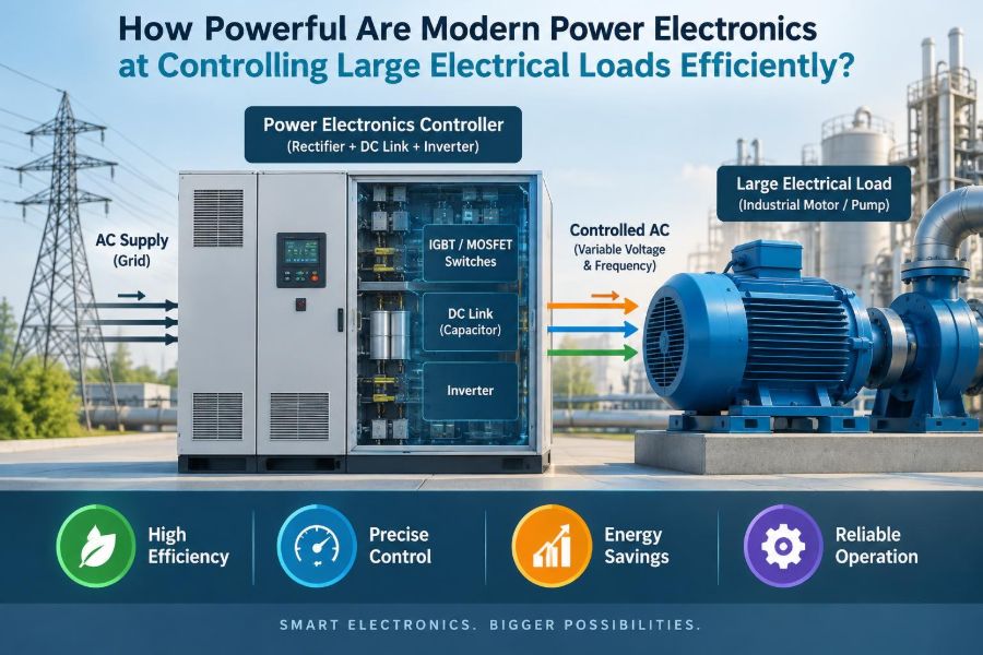
Most power converters perform one of four basic transformations: AC to DC, DC to AC, DC to DC, or AC to AC. A rectifier converts AC to DC; an inverter converts DC to controlled AC; a chopper changes a DC level; and an AC controller changes aspects of an AC supply.
Real systems often combine these stages. A variable-speed drive may rectify the grid supply to DC, smooth it in a DC link, then invert it into three-phase AC at the voltage and frequency the motor needs.
This architecture separates the input supply from the output requirements, which is why one fixed-frequency utility source can run many different motor speeds.
🎛️ Voltage, Current, Frequency, and Phase
A converter’s control authority is broader than simply “turning power down.” For a resistive heater, changing effective voltage mainly changes heating power. For an AC motor, changing frequency changes the speed of the rotating magnetic field.
Current control is equally important. It limits torque, protects components, shapes battery charging, and helps grid-connected equipment meet operating requirements. Phase control and reactive-power control can also influence how AC equipment exchanges energy with the network.
Large-load control is therefore a coordinated problem: deliver enough energy for the task while keeping electrical and mechanical variables within acceptable limits.
🧠 Why Closed-Loop Control Makes the Difference
A programmed switching pattern alone is rarely enough. Modern converters use sensors to measure current, voltage, temperature, speed, position, pressure, or torque. A controller compares the measured value with a target and adjusts switching commands continuously.
This is closed-loop control. If a conveyor encounters a heavier product load, the drive can increase motor current to maintain speed. If a pump discharge pressure reaches its setpoint, the drive can slow the pump instead of forcing a valve to waste energy.
The controller must respond quickly but not aggressively enough to create oscillation. Good tuning is one reason two similar drives can behave very differently in the field.
🧩 The Semiconductor Devices Doing the Work
Different devices suit different voltage, current, speed, and cost requirements. MOSFETs switch very quickly and are widely used at lower and moderate voltages. IGBTs are common in many industrial drives because they handle substantial power with practical switching performance.
Thyristors, including gate-turn-off variants and related high-power devices, remain useful where very high voltage or current capability is needed. Newer wide-bandgap materials, especially silicon carbide and gallium nitride, can reduce switching losses or allow higher switching frequencies in suitable applications.
No device is universally best. Selection depends on the full system: voltage class, switching frequency, cooling method, fault behavior, supply constraints, and expected duty cycle.
📈 Pulse-Width Modulation Shapes the Output
Pulse-width modulation, or PWM, is a common technique for controlling average voltage and current. Instead of producing a perfectly smooth voltage directly, a converter sends a series of rapid pulses whose widths vary according to the desired output.
Motor inductance and added filters smooth much of this switched waveform into useful current. In a motor inverter, PWM can approximate a sinusoidal three-phase supply while retaining fine control over frequency and amplitude.
The trade-off is that switching creates high-frequency components. These can cause extra losses, electromagnetic interference, insulation stress, and audible tones if the system is not designed carefully.
🌀 Variable-Speed Drives Transform Motor Systems
Variable-frequency drives, often called VFDs, are among the clearest demonstrations of power electronics controlling large loads. They allow AC motor speed to follow the actual demand of a pump, fan, mixer, or conveyor.
Historically, many systems used motors running at fixed speed, then controlled output with throttling valves, dampers, or mechanical transmissions. Those methods may be appropriate in some situations, but they often dissipate energy to restrict a flow that the motor could have avoided producing.
A VFD does not guarantee savings by itself. Savings depend on the load profile, operating hours, process needs, and whether speed can truly be reduced. But for many centrifugal pump and fan duties, speed control is particularly valuable.
💨 Why Pumps and Fans Are Special Cases
For many centrifugal pumps and fans, the affinity laws provide a useful approximation: flow varies roughly with speed, pressure varies roughly with the square of speed, and required shaft power varies roughly with the cube of speed.
That cubic relationship explains why a relatively modest speed reduction can substantially reduce required power. It also explains why this rule should not be casually applied to every machine. Positive-displacement pumps, conveyors, compressors, and machine tools have different torque and power characteristics.
Engineers must identify the actual load curve before promising an efficiency improvement.
🚆 Controlling Torque in High-Inertia Machines
Large loads are often difficult not because their steady-state power is extreme, but because changing their speed takes energy. A loaded crane, flywheel, rolling mill, or train has significant inertia and may require carefully limited acceleration torque.
A drive can ramp speed and regulate current so that acceleration stays within motor, converter, gearbox, and supply limits. This is much gentler than abruptly applying full voltage to a large motor.
Torque control also improves process quality. A winder can maintain web tension, while an extruder can avoid torque spikes that might damage material or mechanical components.
🟢 Soft Starting Is Not the Same as Speed Control
A soft starter reduces the voltage applied during motor starting, often using controlled semiconductor devices. Its purpose is to reduce inrush current and mechanical shock during acceleration.
After the motor reaches normal speed, many soft starters bypass their semiconductor path with a contactor. They are generally simpler and less expensive than VFDs when continuous speed adjustment is unnecessary.
A common mistake is to treat soft starters as efficiency devices for variable-flow processes. They solve starting problems well, but they do not normally provide ongoing speed control in the way a VFD does.
🔋 Bidirectional Power Flow Changes the Possibilities
Some modern converters operate in both directions. They can supply energy to a load during motoring and return energy to a battery, DC bus, or AC supply when the load slows down.
This is regenerative operation. An electric vehicle recovering energy during braking is a familiar example. Industrial hoists, elevators, and centrifuges may also produce recoverable energy while lowering or decelerating, depending on their operating cycle.
Regeneration requires somewhere safe for the returned energy to go. If the supply cannot accept it and no storage is available, a braking resistor may convert that energy into heat instead.
🌡️ Efficiency Has More Than One Loss Mechanism
High-efficiency conversion does not mean zero loss. Semiconductor devices lose power while conducting current, and they also lose energy during each switching transition. Magnetic components, capacitors, cables, cooling fans, and control supplies add further losses.
Higher switching frequency can improve waveform quality and control response, but it commonly increases switching loss. Lower frequency reduces switching loss but can worsen current ripple, torque ripple, and acoustic noise.
Designers choose a practical compromise. The best switching frequency is the one that meets performance, thermal, electromagnetic, and economic requirements together.
❄️ Thermal Design Often Sets the Real Limit
A converter may have semiconductor devices capable of high current, yet its usable output is often limited by temperature. Junction temperatures inside chips must stay within specified limits, and repeated thermal cycling affects long-term reliability.
Heat sinks, forced-air cooling, liquid cooling, thermal interface materials, enclosure ventilation, and ambient temperature all matter. Dust-clogged filters or a failed fan can turn an apparently adequate design into an overheating problem.
Ratings must be read with conditions attached. A converter’s published current capability may assume a particular switching frequency, ambient temperature, altitude, enclosure type, and overload duration.
🛡️ Protection Must Act Faster Than Damage
Large electrical systems can release damaging energy very quickly during faults. Power converters therefore monitor overcurrent, short circuits, DC-link voltage, temperature, phase loss, ground faults, and other abnormal conditions.
Protection is layered. Semiconductor desaturation detection or fast current sensing may command an immediate shutdown, while fuses and circuit breakers provide backup isolation. Software limits help prevent misuse, but they are not substitutes for hardware fault protection.
Protection design must consider fault paths, coordination, and the energy available from capacitors and connected sources. Disconnecting a signal command is not necessarily the same as making stored electrical energy safe.
⚠️ Large Capacitors Store Hazardous Energy
DC links use capacitors to stabilize voltage and provide short-term energy during switching. In high-power equipment, these capacitors can remain charged after incoming power is disconnected.
Safe equipment includes discharge paths, voltage indication, interlocks, and procedures for verifying that stored energy has reached a safe level. However, technicians should never assume that an indicator alone proves an enclosure is safe to touch.
Lockout/tagout procedures, qualified personnel, and manufacturer instructions are essential. Large-load power electronics is not an area for improvised troubleshooting.
🌐 Harmonics Affect the Supply Network
Converters draw and inject currents that may not be perfectly sinusoidal. These waveform distortions are called harmonics. Excessive harmonics can increase heating in transformers and conductors, interfere with equipment, and affect voltage quality.
Input reactors, passive filters, active front ends, multipulse arrangements, and careful system design can reduce these effects. The appropriate solution depends on the network strength, converter type, number of drives, and applicable connection requirements.
Harmonic performance should be assessed at the point where equipment connects to the system, not guessed from the converter’s power rating alone.
📡 Electromagnetic Compatibility Is a Design Requirement
Fast voltage edges from PWM converters can couple noise into sensor wires, communication networks, and nearby control circuits. This is an electromagnetic compatibility, or EMC, issue.
Practical measures include screened motor cables where appropriate, correct shield termination, physical separation of power and signal wiring, grounding designed for high-frequency currents, and filters selected for the application.
Adding a filter after a problem appears may help, but good layout is usually more effective. EMC begins with cable routing, bonding, enclosure construction, and an understanding of return-current paths.
🧯 Motor Insulation and Bearing Currents Need Attention
Motor terminals supplied by a fast-switching inverter can experience voltage transients that differ from a sine-wave utility supply. Long motor cables can amplify these effects through wave reflection, raising insulation stress at the motor terminals.
Common mitigations include output reactors, dV/dt filters, sine-wave filters, suitable cable selection, and motors rated for inverter duty. The correct choice depends on voltage level, cable length, switching characteristics, and motor insulation system.
Common-mode voltage can also contribute to bearing currents in some installations. Shaft grounding, insulated bearings, and proper system design may be needed, particularly in larger machines.
🔌 The Grid Is Not an Infinite, Perfect Source
A converter connected to a stiff industrial supply behaves differently from one connected to a weak rural feeder, generator, or isolated microgrid. Supply impedance affects voltage dips, fault current, harmonic interaction, and stability.
For example, starting or rapidly accelerating a major load may cause a noticeable voltage sag on a weak system. A drive can limit current more gracefully than direct-on-line starting, but it cannot create unlimited supply capacity.
Grid-connected inverters must also respond properly to disturbances. Their control settings need coordination with the network and protection system, not just local optimization.
🔗 Power Density Is Rising, but Constraints Remain
Modern materials, packaging, control processors, and cooling methods allow more power to fit into smaller equipment than in earlier generations. This is known as increasing power density.
Higher power density can reduce cabinet space and simplify installation, but it concentrates heat and leaves less margin for poor airflow or installation errors. Compact equipment may require more disciplined attention to cable clearances, cooling paths, and service access.
Smaller is not automatically more robust. A physically larger unit operating cooler may be the better choice for a harsh, high-duty industrial environment.
🧮 Ratings Must Match the Actual Duty Cycle
Selecting a converter by motor nameplate kilowatts alone is risky. Applications have different overload requirements: a fan may need little overload, while a crusher, press, or hoist may need substantial torque for short intervals.
The duty cycle describes how load changes over time. It affects semiconductor heating, motor heating, braking requirements, and the size of cables and protective devices.
| Application characteristic | Typical control priority | Common design concern |
|---|---|---|
| Fan or centrifugal pump | Efficient speed reduction | Stable process control at low flow |
| Conveyor | Controlled acceleration and torque | Starting loaded belts without shock |
| Hoist or elevator | Precise torque and braking | Regeneration and safety coordination |
| Crusher or mixer | High short-term overload | Stall behavior and mechanical impact |
Read the converter’s overload curves, not just its headline rating.
🏗️ Mechanical Systems Can Defeat Good Electrical Control
Even an excellent drive cannot correct a badly sized pump, a binding conveyor, a worn gearbox, or an unstable process loop. Power electronics controls energy delivery; it does not remove every mechanical or process limitation.
A pump operating far from its efficient region may suffer vibration or cavitation despite precise speed control. A conveyor with poor belt tracking may still fail. The electrical, mechanical, and process designs must be reviewed together.
This systems view is especially valuable during retrofit projects, where a new converter is added to equipment designed around fixed-speed operation.
🧭 Sensorless Control Has Useful Limits
Many drives estimate motor speed and rotor position from measured electrical signals rather than using a physical encoder. This sensorless control reduces wiring and can work very well across much of an application’s operating range.
However, low-speed torque accuracy, rapid dynamic response, and starting under demanding conditions may require an encoder or resolver. A precision machine axis and a simple ventilation fan do not need the same feedback arrangement.
Choosing feedback should follow performance requirements, not a preference for either maximum simplicity or maximum instrumentation.
🧪 Commissioning Is Where Design Meets Reality
Correct installation and commissioning determine whether a converter delivers its intended performance. Motor data must be entered correctly, control modes selected appropriately, acceleration limits set safely, and protection parameters coordinated with the application.
A practical commissioning sequence often includes:
- Verify wiring, grounding, insulation condition, and protective devices.
- Confirm motor rotation and uncoupled operation where safe and practical.
- Set conservative current, speed, and acceleration limits.
- Test normal operation, stopping, fault response, and required interlocks.
- Observe temperatures, vibration, process behavior, and supply quality under real load.
Changes should be documented. Undocumented parameter adjustments create maintenance problems long after the original installer has left.
🛠️ Maintenance Is More Than Replacing Failed Parts
Power converters have few moving electrical contacts, but they still require maintenance. Cooling fans, capacitor aging, contaminated heat sinks, loose terminals, degraded cable insulation, and environmental moisture can all reduce reliability.
Condition monitoring may reveal rising temperature, unusual DC-bus ripple, repeated current-limit events, or increasing fault frequency before a major failure occurs. Trends are usually more informative than one isolated measurement.
Maintenance plans should account for the environment. A clean climate-controlled room and a dusty, corrosive processing area demand very different inspection intervals.
💰 Efficiency Must Be Evaluated Across the Whole System
It is tempting to focus only on converter efficiency, which is often high under appropriate conditions. But the larger opportunity may lie in reducing unnecessary output from the driven system, eliminating throttling losses, recovering braking energy, or matching equipment capacity to demand.
Conversely, a highly efficient converter cannot justify a project if process requirements demand constant speed and no controllable losses exist. The economic case depends on operating hours, load variation, maintenance effects, downtime risk, and integration costs.
The right question is not “How efficient is the drive?” but “How does controlled operation change the energy and reliability of the entire process?”
🌱 Electrification Depends on Capable Converters
Power electronics supports electrification across transport, heating, manufacturing, and energy storage. It allows batteries to interface with motors, renewable generators to interface with AC networks, and electrical machines to replace some fuel-driven equipment.
Its contribution is not simply conversion efficiency. Fast control can make electric systems responsive enough for tasks that once depended on throttles, hydraulic valves, gear changes, and combustion-engine speed variation.
That does not mean every application should be electrified in the same way. Infrastructure, duty cycle, source capacity, safety requirements, and lifecycle considerations remain decisive.
🧱 Common Mistakes When Specifying Large-Load Control
Several errors appear repeatedly in otherwise capable projects:
- Choosing equipment only by nominal motor power rather than current and overload duty.
- Ignoring ambient temperature, altitude, enclosure heat, or contaminated air.
- Using long motor cables without considering reflected-wave voltage stress.
- Assuming a drive resolves mechanical faults or process instability.
- Neglecting harmonics, EMC, grounding, and upstream protection coordination.
- Setting acceleration rates based on impatience rather than load inertia and supply capability.
These are not minor details. They determine whether a system operates quietly for years or becomes a recurring source of trips and equipment damage.
🔍 A Practical Way to Judge Converter Capability
When evaluating how “powerful” a power-electronic solution is, ask several connected questions. What voltage and current can it safely handle? How much overload can it deliver, and for how long? Can it control the required speed, torque, temperature, or power factor with adequate accuracy?
Then ask what happens around the converter: Can the supply support the demand? Can heat be removed? Are the motor, cables, mechanical system, and protective devices compatible? Is there a safe path for regenerated energy?
Capability is therefore not a single number on a datasheet. It is a system-level match between converter, load, source, environment, and control objective.
✅ The Core Principle: Precise Switching Enables Useful Power
Modern power electronics can control very large electrical loads with extraordinary precision. They can start heavy machines gently, regulate torque and speed, reshape electrical waveforms, recover energy during braking, and connect variable energy sources to stable electrical systems.
Its efficiency comes from using semiconductor switches primarily in low-loss on and off states, then applying feedback control to deliver only the power the task requires. Yet switching speed, heat, harmonics, insulation stress, protection, and system integration set real boundaries.
The most successful installations treat the converter as part of an engineered system rather than a standalone black box. That approach turns fast electronic switching into dependable, controllable mechanical and electrical work.
Modern power electronics is powerful not merely because it handles high energy, but because it applies that energy with control, timing, and restraint. ⚡🔧🌍