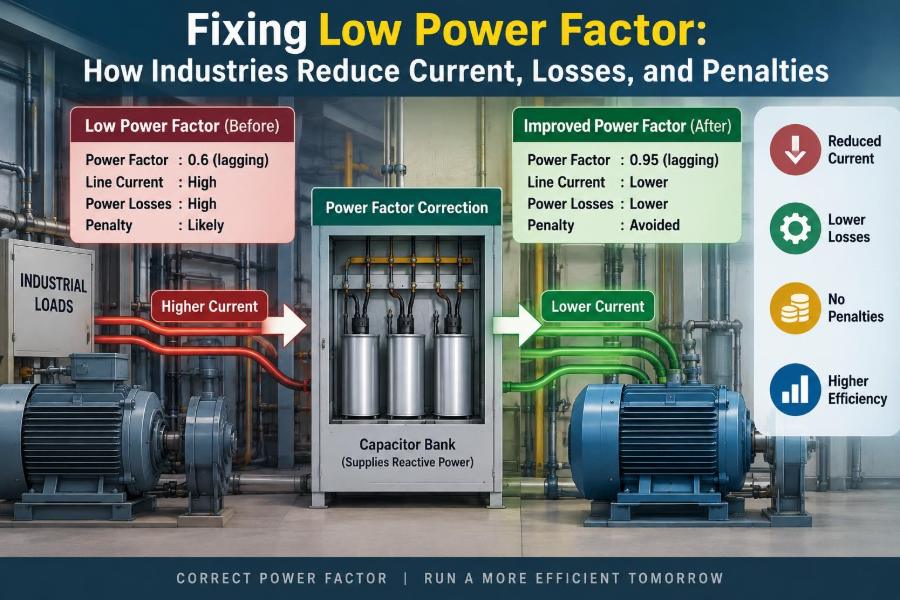

A production line is running normally, yet the main switchboard feels busier than the real power demand suggests. Feeders carry high current, transformers have little spare capacity, and the monthly electricity bill includes a charge that is not explained by kilowatt-hours alone.
This is a familiar industrial problem: low power factor. It often appears where motors, welders, transformers, and other magnetic loads are essential to the process. Nothing may be visibly broken, but the electrical system is carrying current that does not translate fully into useful work.
Improving power factor can release capacity, reduce certain losses, and avoid utility penalties. It is not, however, a matter of simply installing the largest capacitor bank available. A sound correction project begins with measurements, load knowledge, and an awareness of harmonics.
The goal is to make the electrical system carry the current it needs—no more—and to do so safely as operating conditions change.
⚙️ What Power Factor Actually Measures
In AC systems, power factor describes how effectively supplied electrical power becomes useful real power. It is the ratio of real power, measured in kilowatts (kW), to apparent power, measured in kilovolt-amperes (kVA).
Real power produces heat, light, motion, and process work. Apparent power represents the total voltage-current burden placed on cables, transformers, generators, and switchgear.
For sinusoidal voltage and current, power factor is commonly written as PF = kW / kVA. A value close to 1 means kVA is being used efficiently; a lower value means more apparent power is required for the same useful kW.
📐 Real, Reactive, and Apparent Power
Three related quantities make power factor easier to visualize. Real power (P) is measured in kW, reactive power (Q) in kilovolt-ampere reactive (kvar), and apparent power (S) in kVA.
They form the familiar power triangle: S² = P² + Q². Reactive power is not simply “wasted power.” It is energy that moves back and forth between the source and inductive or capacitive fields, supporting equipment operation without producing net useful work over a cycle.
An induction motor needs magnetizing reactive power to establish its magnetic field. The operational issue is that this reactive demand still increases current and therefore consumes network capacity.
🧭 The Phase-Angle View
With a predominantly inductive load, current lags voltage. The displacement power factor is the cosine of that phase angle: cos φ. A larger lagging angle means a lower displacement power factor.
Imagine two workers pulling a cart: one pulls straight ahead while the other pulls partly sideways. Both apply effort, but only the forward component moves the cart. Likewise, only the in-phase current component delivers real power.
This picture is useful, but modern facilities also need to consider distorted waveforms. Harmonics can lower the true power factor even when the fundamental phase angle looks acceptable.
🏭 Why Industry Encounters Low Power Factor
Industrial sites often combine many inductive loads, sometimes operating at partial load for long shifts. Their combined magnetizing demand can make the facility power factor lagging and low.
Common contributors include motors, transformers, induction furnaces, arc welding equipment, magnetic lifting systems, and discharge lighting with magnetic ballasts. Variable-speed drives may change the picture by adding harmonic distortion as well as reactive-power behavior.
The problem is most pronounced when machines are energized but lightly loaded. A motor may still require substantial magnetizing current even when its mechanical output is modest.
🔩 Induction Motors as the Main Contributor
Induction motors are usually the first loads investigated because they are widespread and often numerous. Their stator must establish an air-gap magnetic field, requiring reactive current regardless of the useful shaft load.
At rated load, many motors have a reasonable power factor. At light load, the real-power component falls while magnetizing current remains, so power factor can decline noticeably.
This does not mean every lightly loaded motor should receive a dedicated capacitor. It may instead indicate that the motor is oversized, a process is idling too often, or central automatic correction would suit the site better.
🔌 Other Loads That Pull Power Factor Down
Transformers consume magnetizing reactive power whenever energized, including during low-load periods. Welders and furnaces can produce rapidly changing demand, making a fixed correction scheme inadequate.
- Inductive reactors used for current limiting or filtering add intentional inductance.
- Older lighting systems with magnetic ballasts can draw lagging reactive current.
- Large electromagnets and lifting coils create substantial, sometimes intermittent, reactive demand.
- Underloaded equipment can have poorer power factor than correctly sized equipment doing the same work.
A load inventory should identify both steady demand and short-duration events. A monthly average can hide the switching conditions that matter most.
📊 Why Low Power Factor Raises Current
For a given three-phase real power and line voltage, current rises as power factor falls: I = P / (√3 × V × PF), assuming balanced sinusoidal conditions. That extra current is the central engineering consequence.
For example, a hypothetical 400 V three-phase load using 100 kW draws about 160 A at 0.90 power factor, but about 201 A at 0.72 power factor. The useful output is unchanged; the conductors and upstream equipment see a much larger current.
Actual values depend on voltage, waveform distortion, balance, and measurement method, but the relationship remains: lower PF means greater current for the same kW.
🔥 I²R Losses Grow Faster Than Current
Cable and transformer winding losses are approximately proportional to the square of current: P loss = I²R. This means a current increase has a more-than-proportional effect on resistive heating.
In the hypothetical example, moving from 160 A to 201 A raises the current by roughly one-quarter, but the associated I²R loss factor rises by roughly 58%. The precise site impact depends on conductor resistance and loading.
Correcting power factor does not eliminate all plant losses, nor does it reduce the motor’s mechanical load. It reduces the reactive-current portion flowing through the network sections where correction is applied effectively.
🧯 Voltage Drop and Thermal Stress
Higher current produces greater voltage drop across feeder impedance. At the end of a long feeder, this can leave motors with less terminal voltage during heavy operation, affecting torque and starting performance.
Extra current also adds thermal stress to cable insulation, busbars, contactors, and transformer windings. Equipment may remain within ratings, yet run hotter and have less margin for production expansion.
Power factor correction is therefore often a capacity-management measure as much as an energy-cost measure.
🏗️ Released Capacity in Existing Equipment
Transformers, generators, UPS systems, and switchboards are commonly rated in kVA or amperes, not only in kW. Improving PF allows more real power to be supplied before those current-based limits are reached.
If a transformer is constrained by kVA capacity rather than by losses or voltage, reducing reactive demand may postpone an upgrade. This can be valuable when adding a production cell or charging infrastructure.
It is not a substitute for a capacity study. Fault duty, thermal loading, harmonics, starting currents, and future diversity still need evaluation.
🧾 How Utility Charges Create an Incentive
Utilities must size generation, transmission, and distribution equipment for current and apparent power, not merely for billed kWh. Their tariff structures may therefore include a kVA demand charge, a reactive-energy charge, or a power-factor adjustment.
The exact arrangement is location- and contract-specific. Some tariffs assess charges below a stated threshold; others use peak kVA demand or kvarh. Engineers should read the applicable tariff rather than assume that all low-PF sites are penalized in the same way.
Correction should be economically evaluated using the actual billing interval and demand definition, not a generic savings estimate.
📝 Start With a Load and Bill Review
A useful first step is to review interval data, utility bills, single-line diagrams, transformer ratings, and the operating schedule. Look for demand periods, seasonal changes, shift patterns, and recent process additions.
Then list large motors, drives, welding sets, compressors, furnaces, and transformers. Note their rating, operating hours, loading, starting method, and whether they run together.
This desk review helps determine whether the issue is steady, cyclical, or event-driven before instruments are installed.
📏 Measure at the Right Electrical Locations
A portable power-quality analyzer can log kW, kvar, kVA, PF, voltage, current, demand, and harmonic quantities over representative production periods. A short spot reading during a quiet hour is rarely enough.
Measurements at the main incomer show the utility-facing result. Measurements at transformer secondaries, major motor control centers, and significant nonlinear loads reveal where reactive power and distortion originate.
Use suitable, correctly rated instruments and qualified personnel. Meter connection errors—especially incorrect current-transformer orientation or phase association—can create misleading power-factor readings.
🕒 Capture Normal and Abnormal Operating States
Logging should cover the states that matter: startup, normal production, breaks, low-load operation, and major batch transitions. A correction bank that works well at one operating point can overcorrect at another.
For intermittent machinery, capture switching frequency and the speed of kvar changes. Rapid loads may require closely stepped automatic banks or dynamic compensation rather than a few large fixed stages.
Also investigate unusual low readings. A failed capacitor fuse, a controller issue, or a process change may explain a sudden deterioration.
🧮 Calculating the Required Reactive Compensation
For a load with real power P, initial angle φ₁, and target angle φ₂, the approximate required capacitor rating is Qc = P(tan φ₁ − tan φ₂). Qc is expressed in kvar when P is in kW.
Suppose a hypothetical 500 kW load operates at 0.75 lagging PF and the target is 0.95. Using the corresponding tangent values gives a requirement of roughly 280 kvar. This is a starting calculation, not a final equipment selection.
Load variation, capacitor tolerances, voltage, harmonic conditions, switching steps, and desired margin all affect the installed arrangement.
🎯 Choose a Sensible Target Power Factor
A target near unity is not automatically the best target. Facilities often select a target that satisfies tariff requirements while leaving a margin against leading power factor during light-load periods.
Leading PF means the capacitive effect exceeds the inductive demand. It can cause voltage-rise concerns, unwanted utility billing consequences in some arrangements, and operational problems with generators or lightly loaded transformers.
The appropriate target is based on the tariff, source characteristics, load profile, and the correction system’s control resolution.
🧰 Fixed Capacitors: Simple but Limited
A fixed capacitor bank is permanently connected when its circuit is energized. It is suitable for a fairly constant inductive load, such as a motor that operates near a consistent load for long periods.
Its strengths are simplicity and low control complexity. Its weakness is that it continues producing kvar whenever energized, even after the inductive load falls.
Motor-mounted capacitors need careful coordination with the motor, contactor, starter arrangement, and manufacturer guidance. They must not create self-excitation or unsafe residual-voltage conditions.
🤖 Automatic Capacitor Banks for Variable Loads
An automatic power-factor-correction bank contains capacitor steps switched by a controller. The controller measures system conditions and connects or disconnects stages to hold PF near its setpoint.
Step size matters. Large steps can make the bank oscillate between undercorrection and overcorrection; very small steps increase equipment complexity. Many installations use a staged sequence chosen around the site’s expected kvar range.
Contactors designed for capacitor switching, discharge resistors, fuses, ventilation, and controller settings are all part of a reliable bank—not optional accessories.
📍 Central, Group, and Local Correction
Correction can be placed at the main switchboard, at a distribution board, or beside individual loads. Each location changes which conductors stop carrying reactive current.
| Approach | Best fit | Main trade-off |
|---|---|---|
| Central correction | Many changing loads | Simple to manage, but downstream feeders still carry reactive current |
| Group correction | A stable motor area or MCC | Balances feeder relief with manageable equipment count |
| Local correction | Large, steady individual loads | Reduces local feeder current, but needs careful switching coordination |
Mixed strategies are common. A large steady motor may justify local correction, while an automatic central bank handles the changing remainder.
🌊 Harmonics Change the Design Problem
Harmonics are waveform components at integer multiples of the fundamental frequency. Nonlinear loads such as rectifiers, drives, UPS systems, and some welding equipment can inject harmonic currents.
Capacitors have lower impedance at higher frequencies. When installed into a harmonic-rich network, they can attract harmonic current or interact with system inductance, amplifying voltage distortion through resonance.
For this reason, power factor and power quality must be assessed together. A capacitor bank that looks correct on a fundamental-frequency calculation may be unsuitable for the actual network.
🎵 Resonance and the Role of Detuned Reactors
A capacitor bank and the upstream system inductance form a resonant circuit. If its resonant frequency is near a prominent harmonic, current and voltage distortion can rise, stressing capacitors, cables, and transformers.
Detuned capacitor banks add series reactors. The reactors shift the resonance to a safer frequency and limit harmonic current flowing into the capacitors. They are not identical to active harmonic filters; their purpose is primarily to protect and stabilize the correction bank.
A harmonic survey and system study should guide reactor selection. Guessing a reactor percentage or copying a neighboring plant’s design is not an engineering method.
⚡ Active Power-Factor Correction and Filters
Active power filters use power electronics to inject compensating current. Depending on their design, they can address reactive power, selected harmonic currents, and load unbalance dynamically.
They can be especially useful where loads change quickly or harmonic content is high. Their higher cost, control requirements, heat output, and maintenance expectations should be weighed against the electrical problem they solve.
Some facilities use a hybrid approach: detuned capacitor banks provide bulk kvar economically, while active filtering manages rapidly varying residual reactive power and harmonics.
🔄 Switching Transients Need Attention
Switching a capacitor step can create inrush current and transient voltage effects. Repeated switching can shorten component life if the equipment is not rated and configured for capacitor duty.
Common protective measures include capacitor-duty contactors, pre-insertion arrangements where appropriate, thyristor-switched stages for very rapid loads, correctly sized fuses, and discharge paths before reconnection.
Do not reconnect a discharged capacitor too quickly. Residual voltage combined with system voltage can produce severe inrush.
🧪 Commissioning Is More Than Turning It On
Before energization, verify ratings, wiring, earthing, phase sequence, current-transformer polarity, controller programming, and protective-device coordination. Confirm that capacitor stages are connected as designed and that ventilation paths are clear.
During commissioning, observe step switching under different load conditions. Record PF, kvar, voltage, current, harmonic levels, and capacitor-bank temperature. Compare results with the design assumptions.
A commissioning record becomes valuable later when a controller setting changes or production load evolves.
🔍 Maintenance Signs That Should Not Be Ignored
Capacitors age, contactors wear, fuses operate, and ventilation becomes blocked by dust. A bank can look normal from outside while delivering much less kvar than expected.
- Inspect for bulging capacitor cans, leaks, discoloration, loose terminations, and abnormal noise.
- Check stage currents and balance between phases against expected values.
- Review controller alarms, switching counts, and actual achieved PF.
- Use thermal inspection where appropriate to identify hot connections or failing devices.
Maintenance intervals should follow the equipment documentation and the site’s duty, temperature, contamination, and harmonic environment.
🚫 Common Correction Mistakes
The most common error is sizing from a single low-PF reading rather than a representative load profile. This often leads to an oversized bank that becomes leading during low production.
Another is treating all capacitor banks as interchangeable. A standard bank installed downstream of substantial variable-speed drives may face harmonic overstress unless the network has been assessed.
Other avoidable mistakes include ignoring failed stages, locating correction where it does not relieve the constrained feeder, and assuming lower PF always means poor energy efficiency at the machine itself.
🛡️ Safety, Standards, and Professional Responsibility
Capacitor systems store energy after isolation. They require proper discharge provisions, lockout/tagout procedures, verification of absence of voltage, and trained personnel. Never rely only on an indicator lamp before touching equipment.
Applicable electrical codes, utility interconnection rules, equipment standards, and site safety procedures vary by jurisdiction. They govern enclosure protection, earthing, fault protection, labeling, clearances, and installation practice.
Where the system includes generators, critical processes, high fault levels, or substantial harmonics, a qualified power-system engineer should review the design and protection implications.
📈 Verifying Financial and Electrical Results
After correction, compare like-for-like operating periods. Check billed kVA or reactive quantities, peak current, transformer loading, voltage profile, and actual production output rather than comparing unrelated months.
Separate savings caused by PF correction from changes in weather, operating hours, demand scheduling, or product mix. This avoids crediting the capacitor bank for reductions caused by a quieter production period.
The strongest result is both electrical and financial: lower avoidable current without leading PF, unacceptable harmonics, or reduced reliability.
🧠 The Core Principle: Manage Reactive Power Deliberately
Low power factor is fundamentally a current-management problem. Inductive equipment requires reactive power, but allowing that demand to travel unnecessarily through every upstream conductor uses capacity and raises resistive losses.
Effective correction supplies reactive power near where and when it is needed, while keeping the whole network stable. The best solution may be local capacitors, an automatic detuned bank, active filtering, better motor sizing, or a combination of these measures.
The sequence matters: measure the load, understand the tariff and waveform, choose the target, design for switching and harmonics, then verify performance over real operating conditions.
Industries reduce current, losses, and avoidable charges not by chasing a perfect number, but by matching reactive-power compensation to the actual electrical system. ⚡🏭📉