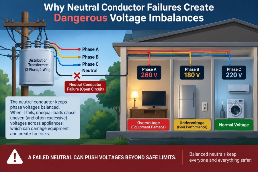

A row of lights suddenly becomes unusually bright while a refrigerator struggles to start. In another room, a phone charger fails, and a voltmeter at the receptacle gives a reading that does not make sense. These symptoms can appear unrelated, but they may share one serious cause: a failing neutral conductor.
Neutral problems are often less dramatic than a short circuit. There may be no large fault current, no immediate breaker trip, and no visible damage at first. Yet an open or high-resistance neutral can move circuit voltages far away from the values that equipment expects.
This matters in homes, offices, workshops, and industrial facilities. Modern loads contain electronics, motors, controls, and power supplies that can be damaged by sustained overvoltage or unstable voltage.
Understanding the neutral as a current-carrying circuit conductor—not merely a harmless “return wire”—helps engineers and technicians recognize the hazard, test safely, and choose reliable corrective action. ⚡
🔌 1. The neutral completes many AC circuits
In a grounded AC system, the neutral conductor is normally connected to the system’s grounded point, often the center point of a transformer winding or the star point of a three-phase wye source.
For line-to-neutral loads, it provides the normal return path for load current. A lamp, control transformer, receptacle load, or electronic power supply may depend on that path to receive its intended voltage.
Calling neutral “ground” can obscure its real function. It is intentionally grounded at defined points, but during normal operation it can carry substantial current.
🧭 2. Grounded does not mean current-free
The neutral is commonly called the grounded conductor because it is connected to earth at the service source or another defined system point. That label does not mean it is equivalent to the equipment grounding conductor.
The equipment grounding conductor is intended primarily to carry fault current and hold exposed conductive parts near earth potential. The neutral is part of the ordinary load circuit.
- Neutral: normal return path for line-to-neutral loads.
- Equipment grounding conductor: fault-current path and bonding conductor.
- Grounding electrode system: connection to earth for system reference and stabilization.
Confusing these functions leads to unsafe troubleshooting assumptions.
🏠 3. The familiar split-phase residential example
Many residential services use a center-tapped transformer secondary. The two ungrounded conductors, often called Line 1 and Line 2, have opposite instantaneous polarity relative to the center tap.
Each line-to-neutral circuit is nominally about 120 V, while the voltage from Line 1 to Line 2 is about 240 V. The center tap is the neutral point.
When the service neutral is sound, 120 V loads on either line have a stable reference. When that neutral opens, loads on opposite lines can become electrically linked in series across the 240 V supply.
⚖️ 4. An open neutral turns loads into a voltage divider
With an intact neutral, a 120 V load is connected from one line to the neutral. With an open upstream neutral, a load on Line 1 and a load on Line 2 may form a series path from one line, through both loads, to the other line.
The 240 V line-to-line source remains present, but the voltage division is determined by the two load impedances. Neither load is guaranteed to receive 120 V.
A high-impedance load can receive a disproportionately high share of the voltage. A lower-impedance load can receive a lower share. The values can change every time a load switches on or off.
🧮 5. A simple voltage-division illustration
Consider two resistive loads connected in series across 240 V because their shared neutral is open. If their resistances are equal, each receives approximately 120 V.
If one resistance is much larger, it receives more voltage. In the ideal resistive case, the voltage across a load is proportional to its resistance: Vload = Vsource × Rload / (R1 + R2).
Real installations are more complicated because motors, electronic supplies, thermostats, and switching loads are not fixed resistors. Still, the voltage-divider model explains the core danger.
📈 6. Why some devices become dangerously overvolted
A lightly loaded circuit can have relatively high effective impedance compared with a heavily loaded circuit on the opposite line. In an open-neutral condition, the lightly loaded side may rise toward the full line-to-line voltage.
For a device designed for approximately 120 V, a voltage approaching 240 V can destroy input capacitors, surge components, control boards, lamps, and small power supplies very quickly.
The dangerous side is not always predictable by room or panel position. It changes with the active loads connected to each line.
📉 7. Undervoltage can be harmful too
The lower-voltage side of an imbalance is not necessarily safe. Motors may draw abnormal current, fail to develop adequate torque, overheat, stall, or repeatedly cycle their protective devices.
Contactors can chatter when coil voltage falls. Electronic controls may reset repeatedly, misread sensors, or behave erratically before they fail.
Neutral failure therefore creates both overvoltage damage and undervoltage malfunction, sometimes simultaneously.
🏢 8. The same principle applies to three-phase wye systems
In a three-phase, four-wire wye system, phase-to-neutral loads are intended to see the phase voltage. The neutral carries the unbalanced component of the phase currents.
If the neutral opens while unequal single-phase loads remain connected, the load star point is no longer firmly tied to the source star point. It can shift in voltage.
This is often called neutral displacement or star-point shift. Phase-to-neutral voltages then depend on the connected load impedances rather than staying balanced at their intended values.
🌐 9. A floating star point has no stable reference
With a solid neutral, the source star point fixes the reference for all phase-to-neutral loads. With a disconnected neutral, the load-side star point is floating.
The three load impedances interact as a network across the line-to-line source voltages. A heavily loaded phase tends to pull the floating point toward its own phase potential, changing the voltages experienced by the other loads.
Balanced loads may continue to see approximately balanced voltages even with no neutral connection. The problem becomes severe when the loads are unequal—which is common in real buildings.
🔄 10. Nonlinear loads complicate the current picture
Computers, LED drivers, variable-speed equipment, and many electronic power supplies draw current in pulses rather than as clean sine waves. These are nonlinear loads.
In three-phase four-wire systems, certain harmonic currents can add in the neutral instead of canceling. This can make the neutral carry significant current even when fundamental-frequency phase currents appear fairly balanced.
Harmonics do not change the basic open-neutral mechanism, but they increase heating concerns and make measurement and diagnosis more demanding.
🔥 11. High-resistance neutrals can be as dangerous as open ones
A neutral does not need to break completely to cause trouble. A loose lug, corroded splice, damaged conductor strand, overheated terminal, or poor meter connection can introduce appreciable resistance.
Current through that resistance produces a voltage drop: Vdrop = I × R. The downstream neutral point then moves away from its intended potential.
Unlike a clean open circuit, a high-resistance neutral may be intermittent. Heat, vibration, load level, and thermal expansion can make symptoms appear and disappear. 🔥
🧱 12. Common places where neutral failures occur
Neutral defects can occur anywhere in the return path, from a branch-circuit connection to transformer terminals. The physical location matters because it determines how many downstream loads are affected.
- Service conductors, meter bases, and service equipment terminations.
- Panelboard neutral bars and branch-circuit terminations.
- Junction boxes, multiwire branch-circuit splices, and receptacle feed-through connections.
- Disconnects, transfer equipment, terminal blocks, and control panels.
- Transformer secondary connections and generator neutral arrangements.
A failure upstream of several circuits can produce widespread and confusing symptoms.
🧩 13. Multiwire branch circuits deserve special attention
A multiwire branch circuit commonly uses two ungrounded conductors from opposite legs of a split-phase system and one shared neutral. Properly installed, the neutral carries only the difference between the line currents.
If the shared neutral opens, loads on the two legs can become series-connected across the line-to-line supply. This creates the same voltage-divider effect seen with a failed service neutral, but on a smaller area of the installation.
A loose splice in one box can therefore affect receptacles or lighting far beyond that box.
🛠️ 14. Loose connections generate heat before they fail
Connection heating is governed by P = I²R. Even a small increase in contact resistance can create substantial heat when current is continuous or high.
Heat oxidizes metal surfaces, weakens insulation, and can reduce contact pressure. That raises resistance further, creating a feedback process that may end in a burned termination or an open conductor.
Correct conductor preparation, suitable terminals, proper torque, and periodic inspection where appropriate are reliability measures, not paperwork details.
👀 15. Field symptoms are often inconsistent
Neutral failures can be mistaken for appliance faults because the symptoms depend on which loads are operating. Turning on a heater may make lights elsewhere brighten; turning off a motor may restore them temporarily.
Typical warning signs
- Lights brighten and dim when other loads start or stop.
- Different receptacles show abnormally high or low voltage.
- Electronic equipment fails in more than one area.
- Motors hum, struggle to start, or contactors chatter.
- A neutral terminal is discolored, hot, loose, or smells of overheated insulation.
These signs justify urgent investigation by a qualified person, not repeated trial-and-error operation.
📏 16. Measuring voltage requires the right reference points
A measurement from line to neutral alone can be misleading when the neutral itself is floating. A digital meter has high input impedance and can display voltages caused by capacitive coupling or weak unintended paths.
Useful diagnosis compares several points: line-to-line voltage, each line-to-neutral voltage, neutral-to-ground voltage where the system design permits that check, and voltages under changing load conditions.
The goal is to identify whether the source voltage is stable while the load reference moves. Measurements must be made using procedures appropriate to energized electrical work.
⚠️ 17. A normal-looking line-to-line reading proves little
In a split-phase service with an open neutral, Line 1 to Line 2 may still measure approximately 240 V. That only confirms the two ungrounded conductors and source are present.
It does not show that either line has a solid neutral reference. One line-to-neutral reading might be low while the other is high, and both may change as connected loads change.
This distinction is essential: correct line-to-line voltage does not guarantee correct line-to-neutral voltage.
🧪 18. Load-dependent testing reveals the mechanism
Because neutral displacement depends on impedance, measurements can change when loads are added or removed. This behavior is diagnostic, but deliberately changing loads on a suspected faulty system can worsen equipment damage.
Qualified troubleshooters use planned methods, appropriate instruments, and controlled conditions. They do not rely on random appliance switching or improvised temporary jumpers.
Testing should establish the condition while minimizing exposure to energized parts and minimizing risk to connected equipment.
🚫 19. The equipment grounding path is not a substitute neutral
Using an equipment grounding conductor as a normal neutral path is unsafe and generally prohibited by electrical installation rules. It can place normal load current on bonded metalwork and grounding paths.
Earth itself is also not a reliable low-impedance return path for ordinary load current. Grounding electrodes serve important system functions, but they are not designed to replace a circuit neutral.
A neutral defect must be repaired as a neutral defect, with the intended conductor and approved connections.
🛡️ 20. Overcurrent devices may not detect the problem
Fuses and circuit breakers are designed primarily to respond to excessive current. An open neutral can cause damaging voltage redistribution while current remains below the overcurrent device rating.
A high-resistance neutral may actually limit current while producing heating at the defective connection. That means the breaker may remain closed as the terminal deteriorates.
Protective devices are vital, but they cannot replace sound conductor continuity and sound terminations.
💻 21. Sensitive electronics are especially vulnerable
Many electronic products use components selected for a limited input-voltage range. An abnormal increase in supply voltage can overstress rectifiers, capacitors, switching transistors, surge suppressors, and integrated control circuits.
Some equipment has internal protection that disconnects or shuts down. Others fail without warning, and a surge protector alone may not be designed to sustain an open-neutral overvoltage condition.
Data loss, process interruption, and hidden damage can remain after the voltage appears normal again.
⚙️ 22. Motors and transformers respond differently than resistors
Motors and transformers are inductive, and their behavior changes with voltage, speed, magnetic saturation, and load. They should not be treated as fixed resistors in a simple calculation.
Low voltage can impair motor starting torque, while high voltage can increase magnetic flux and heating in some equipment. Control transformers may deliver abnormal secondary voltage if their primary supply rises.
This is why an open neutral can trigger a cascade: one abnormal load condition changes the network and shifts voltage for other loads again.
🏥 23. Critical facilities need deliberate neutral continuity
Facilities with life-safety systems, process controls, communications equipment, or essential operations should treat neutral integrity as a design and maintenance concern. A single loose connection can affect much more than lighting.
Clear distribution architecture, accessible terminations, documented circuits, proper transfer-switch neutral arrangements, and condition-based inspection help reduce uncertainty during faults.
Where continuity cannot be casually interrupted, maintenance planning and isolation procedures become especially important.
📐 24. Good design reduces the likelihood and impact
Design cannot eliminate all failures, but it can avoid predictable weak points. Conductors, terminals, and assemblies must be selected for the application, environment, current, and expected harmonic content.
- Use correctly rated and listed connection methods.
- Provide adequate space and access for inspection and termination.
- Keep neutral identification clear and preserve circuit documentation.
- Coordinate shared-neutral circuits and their disconnecting means correctly.
- Consider load balance while recognizing that balance changes over time.
Good design supports safe installation, testing, expansion, and maintenance.
🔍 25. Inspection should focus on evidence, not assumptions
Inspection may include checking conductor condition, terminal security, signs of heating, discoloration, corrosion, insulation damage, and unusual neutral-to-ground voltage under load. Thermal imaging can help identify hot connections when used by competent personnel.
However, a cool connection at one moment is not proof of a reliable connection. An intermittent defect may only appear at a particular load level or after the connection warms.
Records of symptoms, measurements, affected circuits, and corrective work make recurring faults easier to diagnose.
🧯 26. Respond safely when an open neutral is suspected
Unstable voltage is a reason to act promptly. Protect people first, then protect equipment by following the site’s electrical safety procedures and involving qualified electrical personnel.
Do not touch exposed conductive parts, attempt repairs on energized equipment without proper qualification, or assume a device is safe because it is switched off. A switched-off load may still have energized conductors nearby.
If abnormal voltage is affecting equipment, controlled de-energization and professional fault location are usually safer than continued operation.
🧠 27. The core principle: voltage needs a stable reference
A neutral conductor does more than complete a path. In line-to-neutral systems, it establishes the reference that keeps individual load voltages where designers expect them to be.
When that reference becomes open or resistive, connected loads can determine their own voltage division. Unequal loads then create neutral displacement, producing simultaneous overvoltage on some circuits and undervoltage on others.
The central lesson is simple: a failed neutral can transform a normal supply into an unpredictable voltage-divider network, even while line-to-line voltage appears normal. ⚡🛡️🔌