
A bottling line is running at full speed when a photoelectric sensor detects a gap where a bottle should be. In a fraction of a second, a conveyor must stop or divert product, a filling valve must remain closed, and an operator may need an alarm. If those actions happen in the wrong order, the result can be spilled liquid, damaged equipment, or unsafe work.
In modern factories, water-treatment plants, warehouses, and process facilities, this type of decision happens continuously. The device coordinating many of these decisions is often a programmable logic controller, or PLC.
A PLC is not simply a small industrial computer that turns motors on and off. It connects electrical signals from the real world to a defined control strategy, then sends dependable commands back to actuators. Its value comes from making repeatable, observable, and modifiable automation practical.
Understanding PLCs helps electrical engineers, technicians, and operations professionals see how control panels become working industrial processes rather than collections of disconnected wires. ⚙️
🏭 1. What a PLC Actually Does
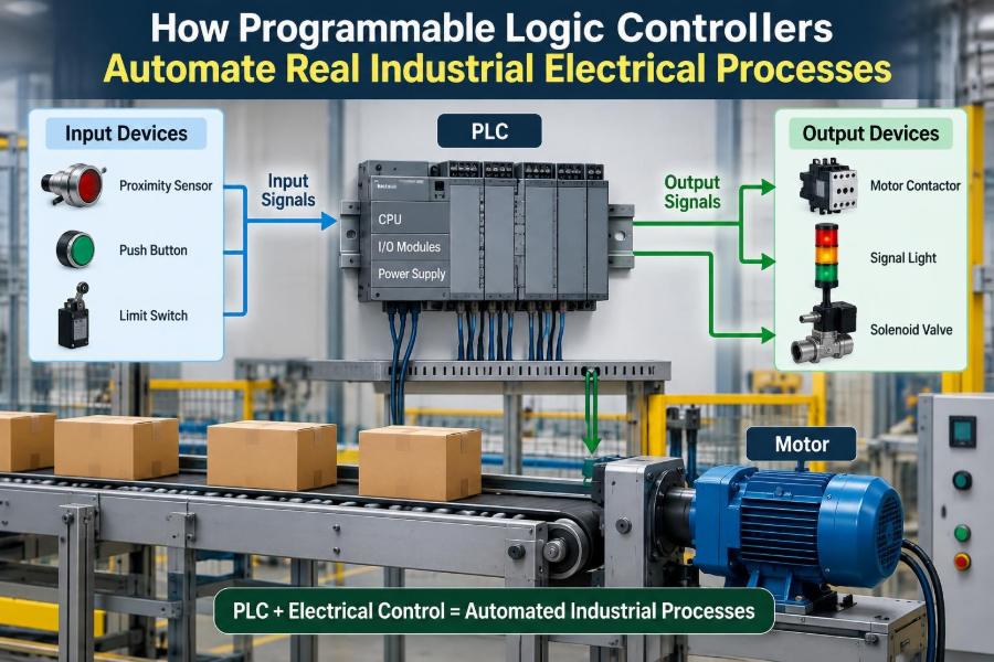
A PLC is a rugged digital controller designed to operate industrial machinery and processes. It reads input conditions, executes a stored program, and updates output commands in a repeating cycle.
The central idea is straightforward: when defined conditions occur, the controller produces defined actions. The real engineering challenge is deciding which conditions matter, how actions must be sequenced, and what must happen when something fails.
For example, a PLC may permit a pump to start only when a tank level is adequate, a valve is proven open, an emergency-stop circuit is healthy, and no fault is active.
🔄 2. The Scan Cycle Connects Software to Hardware
Most PLCs work through a repeated sequence called the scan cycle. Although manufacturers implement details differently, the familiar pattern is read inputs, execute program logic, and write outputs.
- Input update: the controller captures the current state of connected sensors, switches, and signals.
- Program execution: it evaluates instructions using those stored input values and internal memory.
- Output update: it applies the resulting commands to output channels.
- Housekeeping: communication, diagnostics, and system tasks are handled as required.
This cycle repeats rapidly, but it is not instantaneous. Engineers must account for scan time, input filtering, communication delays, and actuator response when designing fast or safety-critical behavior.
⚡ 3. Why PLCs Belong in Industrial Electrical Environments
Industrial sites expose equipment to electrical noise, vibration, temperature variation, dust, and long cable runs. PLC hardware is intended for this environment and is normally installed in a suitably designed control enclosure.
PLCs also support maintainable wiring practices. Field devices terminate at input and output modules, while logic changes can often be made in software instead of by rewiring large banks of relays.
That does not eliminate electrical design. Proper grounding, shielding, circuit protection, segregation of power and signal conductors, and correctly selected components remain essential.
🧩 4. The Main Building Blocks of a PLC System
A complete PLC system includes more than the processor. It is an electrical and information system extending from the field device to the operator interface.
- Power supply: provides regulated power to the controller and sometimes its modules.
- CPU: stores and executes the application program.
- I/O modules: interface between field signals and the PLC.
- Communication interfaces: exchange data with drives, remote I/O, HMIs, and other systems.
- Programming workstation: configures, documents, and diagnoses the application.
Some compact PLCs combine these functions in one unit. Larger systems commonly use modular racks and distributed I/O near equipment.
📥 5. Inputs Let the PLC Observe the Process
Inputs tell the controller what is happening. A discrete input represents a condition with two meaningful states, such as a limit switch made or not made, while an analog input represents a continuously variable measurement.
Typical discrete input devices include pushbuttons, selector switches, proximity sensors, photoelectric sensors, float switches, overload contacts, and auxiliary contacts on contactors.
Typical analog devices include pressure transmitters, temperature transmitters, flow transmitters, level transmitters, and position sensors. The PLC converts their electrical signal into a value the program can use.
📤 6. Outputs Turn Decisions into Physical Action
Outputs are the PLC’s commands to the process. They may energize a relay coil, operate a solenoid valve, command a motor drive, illuminate a stack light, or send a value across a communication network.
Discrete output modules may use relay, transistor, or triac switching methods. Their suitability depends on the signal type, voltage, load characteristics, switching frequency, and required isolation.
An output module often should not directly power a large motor. Instead, it commands a contactor coil, a motor starter, or a variable-frequency drive that is designed to handle motor power.
🧠 7. Digital Logic Is the Foundation
PLC programs implement logical relationships similar to Boolean logic. An AND condition requires every required condition to be true; an OR condition accepts any one of several conditions; a NOT condition reverses the state.
Consider a conveyor start permissive. The conveyor may run only if the safety circuit is healthy AND the motor overload is healthy AND no downstream blockage is detected.
Conveyor_Run_Permit = Safety_OK AND Overload_OK AND NOT Downstream_Blockage
Writing this clearly makes troubleshooting easier. A technician can examine each condition and identify exactly why the permit is absent.
🪜 8. Ladder Logic Resembles Relay Control
Ladder logic is a widely used PLC language because its visual format resembles traditional relay diagrams. It uses contacts, coils, timers, counters, and function blocks arranged in rungs.
A contact instruction tests a bit or condition; a coil instruction writes a bit or output. The symbols are programming instructions, not necessarily physical contacts and coils, even though the notation is familiar.
Ladder logic works especially well for discrete machine sequences, interlocks, alarms, and motor control. Good ladder programs use meaningful tag names and comments rather than relying on unexplained addresses.
🗂️ 9. Other Programming Languages Have Useful Roles
Industrial control platforms may also support function block diagram, structured text, sequential function chart, and instruction-list-like forms depending on the platform. The best choice depends on the problem and the team maintaining it.
| Language approach | Often useful for | Strength |
|---|---|---|
| Ladder logic | Discrete control and interlocks | Accessible electrical representation |
| Function block diagram | Analog loops and reusable control functions | Clear signal flow |
| Structured text | Calculations, data handling, complex algorithms | Compact expression of logic |
| Sequential function chart | Step-based batches and machine states | Explicit process progression |
Many good applications use more than one approach. Consistency and maintainability usually matter more than choosing the most sophisticated-looking language.
🚦 10. A Real Process Needs States, Not Just Outputs
A motor is not simply on or off in a well-designed automated system. It may be stopped, ready, starting, running, stopping, faulted, manually controlled, or unavailable because another condition has priority.
Representing these modes explicitly prevents conflicting commands. A state-based design also makes the operator display and troubleshooting process much clearer.
For a mixing tank, states might include idle, filling, mixing, discharge, cleaning, and fault. Each state defines which outputs are allowed and which transition conditions move the process to the next state.
🔒 11. Interlocks Prevent Incorrect or Damaging Actions
An interlock prevents an action unless necessary conditions are satisfied. Interlocks protect equipment, support correct sequencing, and reduce the chance that a command creates an undesirable process condition.
Examples include preventing two opposing valves from opening together, blocking a pump start with a low suction level, or preventing a machine cycle while a guard is open.
Not all interlocks have the same purpose. Some protect machinery, some enforce process quality, and some are part of a dedicated safety function. Engineers must not assume that ordinary PLC logic alone provides a safety function.
🛑 12. Safety Control Requires Deliberate Architecture
Emergency stops, protective guards, light curtains, and safety-rated sensors may require dedicated safety relays or safety PLC systems. These systems are designed and validated for safety functions, with architecture, diagnostics, and performance requirements appropriate to the application.
A standard PLC can report safety status and coordinate a controlled process response, but it should not be casually substituted for a properly designed safety system. Risk assessment and applicable regulations guide the required approach.
Safe design also considers stored energy, unexpected restart prevention, isolation procedures, and the behavior of equipment after power loss or communication failure. 🛑
⏱️ 13. Timers Shape Industrial Sequences
Timers make sequencing possible. They can delay an action, require a condition to remain true for a period, pulse an output, or supervise whether an expected event occurs on time.
A pump may start several seconds after a valve-open command so the flow path is established. A sensor signal may require filtering so a brief vibration does not trigger a false fault.
Timeouts are equally important. If a valve is commanded open but its feedback does not arrive within an expected period, the PLC can stop the sequence, announce a fault, and place the system in a safer condition.
🔢 14. Counters Track Events and Production
Counters register repeated events such as products passing a sensor, machine cycles completed, or pulses received from an encoder. They can support production totals, batching, maintenance intervals, and sequence decisions.
A counter alone is not automatically accurate. Sensor placement, product spacing, signal quality, missed pulses, and reset rules all affect whether the final count represents the real process.
For critical measurement, engineers define what constitutes one valid event and include logic to reject impossible duplicates or signals that occur too quickly.
📈 15. Analog Signals Bring Measurement into Control
Many industrial measurements use standardized electrical ranges, commonly current or voltage signals. A transmitter might represent a physical pressure, temperature, level, flow, speed, or position as a signal delivered to an analog input.
The raw input value is not automatically meaningful to an operator. The PLC program scales it into engineering units, such as a pressure range or tank level range, based on the configured sensor and input characteristics.
Scaling must be documented and tested. An incorrect range, wiring error, or mismatched configuration can create believable but false process values.
🎛️ 16. Closed-Loop Control Responds to Change
Discrete logic answers questions such as whether a valve should open. Closed-loop control adjusts an output continuously or repeatedly to hold a measured process variable near a desired setpoint.
A common example is maintaining tank level by changing a pump speed or control-valve position. The controller compares measured level with the desired level and calculates an output correction.
Many PLCs provide PID control functions, named for proportional, integral, and derivative actions. Correct tuning depends on the process dynamics; aggressive tuning can create oscillation, while weak tuning can make response sluggish.
🌀 17. Motor Control Is a Core PLC Application
Motors drive pumps, fans, conveyors, compressors, mixers, hoists, and many other industrial loads. PLCs coordinate motor operation, but the motor branch circuit and starter equipment must be selected and protected according to electrical design requirements.
A basic motor control sequence often includes a start command, run permissive, starter feedback, overload status, stop command, and fault alarm. Feedback matters because a command to run does not prove the motor actually started.
For variable-speed applications, a PLC may send a speed reference to a drive and receive running, fault, speed, current, or diagnostic information in return.
🧯 18. Fault Handling Must Be Designed, Not Added Later
A useful PLC program anticipates abnormal conditions. These include sensor disagreement, motor overloads, loss of feedback, excessive process values, communication loss, and sequence timeouts.
Each fault should have a defined response: stop immediately, complete a controlled stop, inhibit restart, switch to a backup device, or notify an operator while allowing operation to continue. The right response depends on the hazard and process consequences.
Fault messages should identify the condition and equipment clearly. “Pump P-101 failed to prove running” is more actionable than a vague message such as “system error.”
📣 19. Alarms Need Priority and Meaning
An alarm is a request for attention, not merely any condition that can be displayed. Too many alarms, especially repetitive nuisance alarms, make it harder for operators to recognize urgent problems.
Good alarm design distinguishes informational events from conditions requiring action. It provides a meaningful description, an appropriate priority, and where possible an indication of the response expected from the operator.
Alarm acknowledgment does not necessarily clear the underlying condition. The program should distinguish between acknowledging that an alarm was seen and confirming that the process is genuinely back within acceptable limits.
🖥️ 20. HMIs Make Automation Visible and Usable
A human-machine interface, or HMI, presents process status and accepts authorized operator commands. It may show tank levels, valve states, trends, alarm lists, setpoints, operating modes, and maintenance information.
An effective HMI reflects the real process without becoming a decorative imitation of it. Operators need clear status, abnormal-condition visibility, and controls that reveal whether a request was accepted, blocked, or still in progress.
Mode control deserves care. A manual command should not silently bypass important protections, and the display should make automatic, manual, and maintenance states unambiguous.
🌐 21. Industrial Networks Reduce Wiring but Add Design Work
Communication networks allow PLCs to exchange data with remote I/O, motor drives, instruments, HMIs, and higher-level systems. This can reduce point-to-point wiring and provide richer diagnostics than simple hardwired signals.
However, a network is not a magic cable. It requires addressing, topology planning, cable selection, electromagnetic-noise awareness, managed access, and a defined response to communication loss.
Critical control functions need a predictable strategy if data becomes unavailable. A drive may need to stop, hold its last command briefly, use a preset fallback, or transfer control according to the process design.
🧱 22. Remote I/O Brings Signals Closer to Equipment
Instead of running every sensor and actuator conductor back to one large cabinet, remote I/O stations can be installed near machines, valve manifolds, or field junction points. A network links those stations to the main controller.
This can simplify installation and reduce cable lengths, particularly in large facilities. It also means the field enclosure still needs thoughtful power distribution, environmental protection, grounding, labeling, and maintenance access.
Distributed architecture should make faults easier to isolate, not harder. Clear drawings and physical labels are just as valuable as network configuration files.
🧾 23. Electrical Drawings and Software Documentation Must Agree
Automation depends on accurate documentation. Electrical schematics show how devices are connected, while I/O lists associate field devices with PLC channels, tags, signal types, and descriptions.
The PLC program should use the same meaningful tag names that appear in drawings and HMI displays. When a technician sees a tag in an alarm, it should be possible to trace it to a terminal, cable, device, and physical location.
- Maintain an I/O list with signal descriptions and normal states.
- Document interlocks, permissives, setpoints, and sequence narratives.
- Record panel changes and software revisions.
- Keep backup copies that can be identified and restored confidently.
Documentation is a reliability tool, not paperwork left until the end.
🧪 24. Testing Starts Before the Machine Runs
Testing a PLC system is more than downloading a program and pressing start. It begins with review of the control narrative, drawings, I/O assignments, and expected responses to normal and abnormal conditions.
Input and output checks verify that each physical signal is wired, labeled, and interpreted correctly. Simulated conditions can test sequences and alarms before energizing equipment where practical.
Commissioning should confirm not only that equipment can run, but that it stops, alarms, restarts, and recovers correctly. Fault testing is often where hidden assumptions become visible.
🛠️ 25. Troubleshooting Follows the Signal Path
When a process does not behave as expected, troubleshoot systematically. Start with the symptom and trace the command or measurement through the field device, wiring, input or output channel, program logic, and final actuator.
Suppose a solenoid valve does not open. Is the PLC output command true? Is the output channel energized? Is control voltage present at the coil? Is the coil intact? Is air or hydraulic pressure available? Is the valve mechanically stuck?
A PLC’s online diagnostics can be powerful, but they do not replace safe electrical measurement practices. Verify isolation requirements and use suitable test equipment before working in a panel. 🔧
🧑💻 26. Cybersecurity Is Part of Control Reliability
As PLC systems become connected to plant networks and remote support tools, unauthorized access can affect availability, quality, and safety. Cybersecurity is therefore an operational engineering concern, not only an IT concern.
Useful practices include controlling user access, protecting programming connections, separating networks appropriately, managing software changes, maintaining backups, and understanding which devices are permitted to communicate.
Convenience should not create uncontrolled pathways into a running process. A change to logic, setpoints, or drive commands can have physical consequences.
📚 27. Skills That Make PLC Engineers Effective
Strong PLC work combines several disciplines. Programming ability matters, but it becomes genuinely useful when paired with electrical fundamentals, process understanding, instrumentation knowledge, and disciplined troubleshooting.
- Read schematics, panel layouts, and motor-control diagrams.
- Understand sensors, signal conditioning, and actuator behavior.
- Write clear sequences, interlocks, alarms, and operating modes.
- Use structured naming, comments, revision control, and test records.
- Communicate with operators, maintenance teams, and process specialists.
The most valuable automation engineers ask not only “Does the code work?” but also “What happens if this sensor fails, power returns, or an operator needs to intervene?”
🧭 28. The Core Principle: Controlled Decisions Create Reliable Processes
A PLC automates industrial electrical processes by repeatedly turning field information into deliberate output actions. Sensors provide evidence, logic applies operating rules, and actuators change the physical process.
Reliable automation comes from more than a controller and a program. It requires correct electrical interfaces, clear sequencing, appropriate safety architecture, useful diagnostics, tested failure responses, and documentation that connects software to the real installation.
The core principle is simple: define how the process should behave in every important condition, then build and verify the electrical control system that makes that behavior repeatable. ⚡🧠🏭