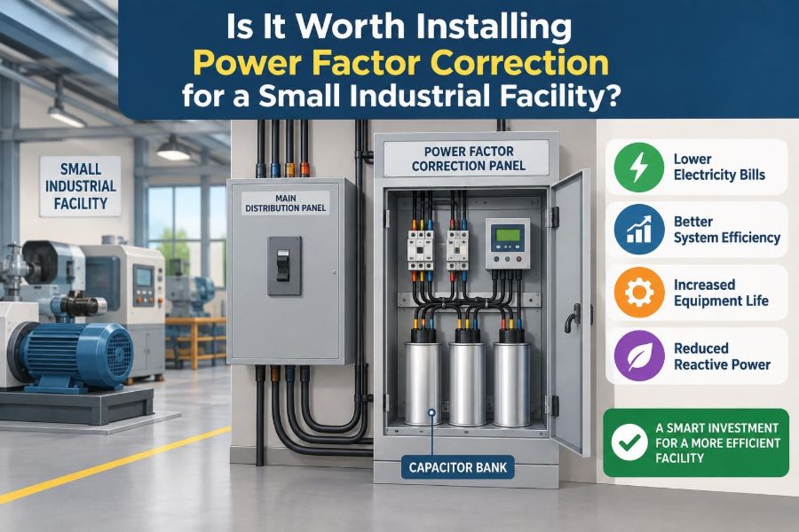

A small factory adds a new air compressor, a few induction motors, and a welding bay. Production improves, but the monthly electricity bill seems oddly high—or the main switchboard is beginning to feel crowded before the facility has reached its expected real-power demand.
Someone suggests installing capacitors for power factor correction. The proposal may sound straightforward: improve power factor, reduce costs, free capacity. Yet for a small industrial facility, the right answer is not always “yes,” and an incorrectly designed capacitor bank can create its own operating problems.
The useful question is not whether power factor correction is good in principle. It is whether the facility has a measurable problem, what is causing it, how the utility bill is structured, and whether correction will remain safe across changing loads.
With a few measurements and a realistic financial calculation, this decision becomes an engineering exercise rather than a guess.
⚙️ What Power Factor Actually Describes
In an AC electrical system, power factor describes how effectively current is being converted into useful work. It is the ratio of real power, measured in kilowatts (kW), to apparent power, measured in kilovolt-amperes (kVA).
Real power runs equipment: it turns a motor shaft, heats a process, or produces light. Apparent power is the total electrical capacity the supply must deliver. When power factor is below 1.0, the system carries more current than would be needed for the same kW at unity power factor.
For a sinusoidal system without significant distortion, power factor is commonly expressed as:
Power factor = kW / kVAA power factor of 0.80 means a load using 80 kW requires 100 kVA of supply capacity. At 0.95 power factor, that same 80 kW requires only about 84 kVA.
🧲 Why Industrial Loads Often Have Low Power Factor
Many industrial loads are inductive. Induction motors, transformers, magnetic ballasts, contactors, and some welding equipment require magnetizing current to establish magnetic fields. This current does not directly produce useful output, but it still occupies part of the electrical system’s capacity.
Motor power factor is often poorest at light load. A motor driving a lightly loaded fan or oversized pump may draw a meaningful magnetizing current even when its mechanical output is modest.
Facilities with many motors that run intermittently can therefore have a power factor that changes substantially through the day. A single reading taken while machinery is idle may not represent the condition that drives billing or equipment loading.
📐 Real, Reactive, and Apparent Power
Reactive power, measured in kilovolt-ampere reactive (kvar), moves energy back and forth between the source and magnetic or electric fields. Inductive equipment generally requires lagging reactive power; capacitors supply leading reactive power.
These quantities are related geometrically. Real power and reactive power are perpendicular components, while apparent power is the combined result. In simplified form:
kVA² = kW² + kvar²Power factor correction reduces the reactive component supplied by the utility or upstream transformer. It does not reduce the kW genuinely required by a motor to do its mechanical work.
🏭 Why a Small Facility Should Care
Low power factor can matter in two separate ways. First, a utility may apply a demand charge, a reactive-energy charge, or a power-factor adjustment under the applicable tariff. Second, the facility’s own cables, transformers, switchgear, and generators must carry the higher current associated with the larger kVA demand.
A site may have a poor power factor but no immediate financial case for correction if its tariff does not penalize it and its electrical infrastructure has ample spare capacity. Conversely, a site approaching transformer or generator limits may gain practical value even if the utility savings are modest.
That distinction prevents a common mistake: assuming every low power factor reading automatically justifies a capacitor bank.
🧾 Start with the Electricity Tariff, Not the Catalog
Before selecting equipment, examine several consecutive electricity bills and the current utility tariff. Look for billed kW demand, kVA demand, kvarh or reactive-energy charges, and any stated power-factor threshold or adjustment.
Utilities use different billing arrangements. Some bill mainly for energy in kWh, some assess maximum demand, and some use kVA demand or apply an adjustment when power factor falls below a specified level. The details can vary by customer class, location, contract, and metering arrangement.
If the bill only charges kWh, correction may not lower the energy portion of the bill. It may still have capacity benefits, but those need their own value calculation.
🔍 Identify the Type of Charge Being Avoided
Do not describe anticipated savings simply as “lower electricity use.” Capacitors mainly reduce reactive demand upstream of their connection point. The bill reduction, if one occurs, comes from avoiding a tariff charge or reducing billed apparent demand.
Useful questions for the utility account manager or qualified energy professional include:
- Is demand measured in kW, kVA, or both?
- Is reactive energy billed separately?
- Is there a monthly power-factor target or threshold?
- Which interval determines maximum demand?
- Could correction change the facility’s demand calculation under this tariff?
Get answers in writing where possible. A generic rule of thumb is not a substitute for the tariff governing the actual account.
📊 Measure a Load Profile Instead of Taking One Snapshot
A portable power-quality analyzer or revenue-grade meter can reveal much more than a panel-mounted power factor display. Measure kW, kVA, kvar, power factor, voltage, current, demand intervals, and harmonic distortion across representative operating periods.
Include normal production, low production, shift changes, and any seasonal loads. If the facility has a compressor that cycles or large motors that start together, short-duration peaks can matter as much as average values.
The objective is to identify both the maximum reactive demand and the lowest-load periods. A correction system must improve the first without becoming excessively capacitive during the second.
🧮 Estimate the Required Capacitor Size
For an initial estimate, the required capacitor rating can be calculated from real power and the desired change in power factor:
Required kvar = kW × (tan φ₁ − tan φ₂)Here, φ₁ is the angle corresponding to the existing power factor and φ₂ corresponds to the target power factor. This calculation is useful for screening options, but it is not a complete design.
Consider a hypothetical facility with a 75 kW measured load at 0.75 power factor, aiming for 0.95. The calculation suggests roughly 42 kvar of correction. In practice, the selection may be several switched steps rather than one fixed 42 kvar bank because the 75 kW load may not be constant.
🎯 Why Unity Power Factor Is Usually Not the Target
It is tempting to target 1.00 power factor, but that is often neither necessary nor desirable. Load variation, capacitor tolerances, voltage changes, and switching steps can cause a system designed for exact unity to become leading.
Many facilities choose a target below unity, such as a value aligned with tariff requirements and operating conditions. The correct target depends on the utility arrangement, the measured load profile, and the risk of overcorrection.
A stable, compliant power factor is more useful than a perfect number achieved only under one load condition.
🧱 Fixed Capacitors: Simple but Limited
A fixed capacitor remains connected whenever its circuit is energized. It can be economical where a motor or transformer operates for long, predictable periods at a relatively constant load.
For example, a capacitor switched with a continuously running, well-loaded motor can reduce reactive current in the feeder serving that motor. This local approach may also reduce current in downstream conductors.
Its limitation is clear: when the motor stops or unloads, the capacitor may no longer match the reactive requirement. Fixed correction should therefore be applied only after checking all relevant operating states.
🔁 Automatic Capacitor Banks Suit Variable Loads
An automatic power factor correction bank uses a controller, current measurement, contactors or thyristor switches, and capacitor steps. The controller adds or removes steps as reactive demand changes.
For a small plant with cycling compressors, multiple motors, and varying shifts, automatic switching can prevent the leading power factor that a large fixed bank might create during light load. Step sizes should be chosen to match the variability of the load.
Very coarse steps can cause repeated switching around the target. Extremely fine steps can add cost and complexity without meaningful operational benefit. The design should reflect actual measurements, not just the nameplate rating of every motor.
⚡ Where the Capacitors Should Be Installed
Correction may be installed at the main low-voltage switchboard, on a distribution bus, or near individual large loads. Each location changes which parts of the system see reduced reactive current.
Central correction is easier to maintain and can address the facility’s utility-metered power factor. Local correction can reduce feeder current and voltage drop near a large continuous inductive load. A mixed approach can be appropriate, but it requires coordinated design.
Do not assume that placing capacitors near every motor is inherently superior. Installation access, motor duty cycle, harmonics, protection, and maintenance responsibility all affect the result.
📉 Capacity Benefits Inside the Electrical System
When reactive current is reduced, the same transformer, cable, or generator can deliver more useful kW before reaching its current or kVA rating. Voltage drop in conductors may also decrease because current is lower.
These benefits are real, but they must be quantified carefully. A transformer that is lightly loaded does not create an immediate economic saving simply because its calculated spare capacity increases.
Capacity value becomes stronger when correction can defer a planned transformer upgrade, avoid a generator uprating, or solve a documented feeder-current constraint. It should not be used to justify loading equipment beyond its thermal, fault-duty, protection, or voltage-regulation limits.
💡 What Correction Does Not Do
Power factor correction does not make an inefficient motor efficient, repair a leaking compressed-air system, or reduce the mechanical power needed by a process. A capacitor bank is not an energy-efficiency substitute for fixing poor controls or oversized equipment.
It also does not eliminate all electrical losses. Lower current can reduce some upstream I²R losses, but the magnitude depends on conductor resistance, load duration, and where the capacitors are installed.
This is why projected savings should separate tariff savings, potential loss reduction, and deferred-capacity value rather than combining them into one vague claim.
🌊 Harmonics Change the Design Question
Modern facilities often contain variable-frequency drives, UPS systems, rectifiers, welders, LED drivers, and other nonlinear loads. These devices draw current in pulses and create harmonic currents that distort the waveform.
In a harmonic-rich system, a plain capacitor bank can interact with system inductance and create resonance. That interaction can amplify certain harmonics, overstress capacitors, overheat transformers, cause nuisance tripping, or increase voltage distortion.
A power-quality survey should therefore assess harmonic current and voltage before capacitors are specified. This is not an optional refinement when substantial nonlinear loads are present.
🎼 Detuned Reactors and Harmonic Filters
A detuned capacitor bank includes series reactors designed to shift the bank’s resonant frequency away from troublesome harmonic frequencies. It is commonly used where harmonic levels make an ordinary capacitor bank unsuitable.
In more demanding cases, passive or active harmonic filtering may be considered. These solutions are not interchangeable: a system intended to correct displacement power factor may not adequately address distortion-related power factor or harmonic compliance concerns.
The required approach depends on measured spectra, source impedance, transformer characteristics, existing capacitors, and future load additions. A qualified power-quality engineer should review this work.
🌀 Displacement Power Factor and True Power Factor
With clean sinusoidal waveforms, the familiar phase-angle relationship describes power factor well. This is often called displacement power factor, because it concerns the phase displacement between voltage and the fundamental component of current.
With distorted current, true power factor also reflects waveform distortion. A facility can improve displacement power factor with capacitors yet retain a disappointing true power factor if harmonics remain high.
For this reason, meter settings and terminology matter. Ask whether the reported value is total power factor, displacement power factor, or an instrument-specific calculation.
🔥 Switching Transients and Contactor Duty
Capacitors can draw high inrush currents when energized, especially if another capacitor step is already connected. Ordinary motor contactors may not be suitable for capacitor switching duty.
Purpose-designed capacitor contactors, pre-insertion arrangements, fuses or protective devices, and correctly rated conductors help manage these conditions. Thyristor-switched banks may be useful where rapid, frequent switching is required, though they bring different cost and design considerations.
Repeated failed contactors or blown capacitor fuses are not normal “maintenance items” to ignore. They can indicate switching, harmonic, voltage, or sizing problems that deserve investigation.
🛡️ Protection, Isolation, and Discharge Safety
Capacitor banks store electrical energy after disconnection. They require suitable discharge resistors, warnings, isolation procedures, and verification of de-energization before work begins.
Protection design must consider capacitor faults, feeder faults, switching duty, and coordination with the existing electrical distribution system. Enclosures, clearances, earthing, ventilation, and access must meet the local electrical code and facility safety practices.
Only qualified electrical personnel should install, commission, troubleshoot, or modify a correction system. The risks include arc flash, electric shock, stored charge, and incorrect phase or current-transformer connections.
🌡️ Heat, Ventilation, and Capacitor Life
Capacitors generate heat and have temperature-sensitive service lives. A bank installed in a hot electrical room, near process heat, or inside an inadequately ventilated enclosure can age prematurely.
Harmonic current and elevated voltage add thermal stress. Loose connections can also generate local heating and degrade terminals or insulation.
Specify equipment for the expected ambient conditions, leave room for ventilation and inspection, and avoid treating a capacitor bank as a fit-and-forget device hidden behind a switchboard door.
🔧 Motor-Specific Correction Needs Extra Care
Capacitors connected directly at motor terminals can be beneficial in the right application, but motor behavior must be understood. A capacitor that remains connected while a motor is disconnected from the supply can contribute to self-excitation or unexpected residual voltage under some conditions.
Correction for motors controlled by variable-frequency drives requires particular caution. In general, capacitors should not be placed on the drive output unless the drive manufacturer and a qualified designer specifically approve the arrangement.
For motor circuits, coordinate correction with the starter type, switching sequence, motor protection, and the equipment manufacturer’s instructions.
🧾 Build a Financial Case from Real Inputs
A credible business case includes installed equipment cost, engineering, installation outage time, commissioning, maintenance, expected tariff savings, and any defensible capacity value. It should use measured demand and the actual billing mechanism.
A simple payback estimate can be useful:
Simple payback = installed cost / estimated annual net savingsBut do not stop there. The estimate should state assumptions: production hours, expected power factor, tariff stability, capacitor losses, maintenance allowance, and whether new nonlinear loads are planned. If the savings rely on a tariff clause, verify that the clause applies to the account.
🧠 A Hypothetical Decision Example
Imagine a small fabrication facility whose interval data shows 60 kW to 90 kW during production, with power factor commonly below the utility’s billed threshold. Its bill includes a charge linked to apparent demand, and the main transformer is nearing its practical operating capacity during busy periods.
For this facility, an automatically switched, properly engineered bank may offer two forms of value: reduced billed demand and released transformer capacity. Harmonic measurements would determine whether a detuned bank is needed.
Now change the scenario: the same facility is billed only by kWh, has a lightly loaded transformer, and sees low power factor primarily during brief idle intervals. The financial case may be weak, even though an instantaneous meter reading looks poor. Measurement and billing context change the answer.
🚩 Signs the Project May Not Be Worth It Yet
Delay the purchase and investigate further when the evidence is incomplete or the benefit is speculative. Warning signs include:
- No utility power-factor, reactive-energy, or kVA-demand charge.
- Only one short-duration power factor measurement is available.
- The proposed bank is sized from motor nameplates rather than measured demand.
- Variable-frequency drives or other nonlinear loads are present but harmonics were not assessed.
- The facility’s load is expected to change substantially soon.
- The proposal promises broad “energy savings” without separating their source.
None of these conditions permanently rules out correction. They simply mean the design or financial analysis is not mature enough for a confident decision.
✅ When the Case Is Usually Stronger
The case is generally stronger when interval measurements show sustained low power factor during billed demand periods, the tariff imposes a clear avoidable charge, and correction can be controlled without leading conditions.
It can also be justified when documented reactive current is limiting a transformer, generator, feeder, or switchboard and a correction system safely defers a larger infrastructure project.
Even then, the preferred solution may not be a standalone bank. Replacing an oversized lightly loaded motor, correcting process control, or addressing a specific poorly performing load can sometimes solve the underlying issue more effectively.
🧭 A Practical Evaluation Workflow
A disciplined sequence keeps the project proportionate to a small facility’s needs:
- Collect at least several representative bills and identify the relevant tariff terms.
- Measure load, reactive demand, and harmonics over representative operating conditions.
- Identify whether the objective is billing reduction, capacity relief, voltage performance, or a combination.
- Calculate preliminary kvar requirements and define a realistic target power factor.
- Evaluate fixed, switched, detuned, or alternative solutions.
- Review protection, switching, layout, ventilation, safety, and future expansion.
- Commission the system and verify results under high and low load.
This workflow also creates a record of why the investment was made, which helps when equipment or tariff conditions change later.
📋 Questions to Ask a Supplier or Contractor
A competent proposal should explain its assumptions, not just state a kvar rating. Ask for the measured inputs, target power factor, step arrangement, harmonic assessment, equipment ratings, protection concept, and expected operating behavior at low load.
Also ask how the controller will be commissioned, what maintenance is required, how failed capacitor elements are detected, and whether the design accounts for planned drives, solar inverters, generators, or transformer changes.
If answers remain vague, seek an independent review. The cost of a brief engineering assessment is often small compared with correcting a poorly matched installation.
🧪 Commissioning Is Where Design Meets Reality
Commissioning should confirm phase sequence, current-transformer polarity and ratio, controller settings, switching order, protection operation, and the actual power factor response. An incorrectly oriented current transformer can make a controller respond in the wrong direction.
Check performance at normal load and reduced load. Record voltage, current, kvar, kW, power factor, and harmonic values before and after correction so the system has a baseline for future troubleshooting.
Verify that correction does not create leading power factor at the utility meter, unacceptable voltage rise, abnormal noise, overheating, or excessive switching.
🔍 Maintenance and Ongoing Verification
Periodic inspection should include visual condition, enclosure cleanliness, ventilation, signs of heating, terminal tightness using approved procedures, fuse status, contactor wear, controller alarms, and capacitor condition indicators where provided.
Recheck the system after major operational changes. New drives, a larger transformer, altered production schedules, generator installation, or a utility meter upgrade can change the behavior of a bank that previously worked well.
Trend data is valuable. A gradual loss of kvar contribution may indicate aging capacitors, failed stages, incorrect control response, or a changed load profile.
⚖️ The Core Decision: Solve the Actual Constraint
Installing power factor correction is worth considering when it solves a verified constraint: a tariff penalty, excessive kVA demand, constrained electrical capacity, or a measurable voltage-drop issue. The equipment should be sized from operating data and designed for the electrical environment, especially harmonics.
It is not automatically worthwhile simply because motors exist or because a meter occasionally shows a low number. Small facilities benefit most from a modest, well-measured solution that can adapt to their loads and be safely maintained.
The core principle is straightforward: correct the reactive power the facility actually needs, at the right location and under the conditions in which that correction creates real value.
For a small industrial facility, power factor correction is a sound investment only when measured load behavior, utility billing, system capacity, and harmonic risk all support the same conclusion. ⚡🏭📈