
A city block can look calm while an immense electrical choreography unfolds out of sight. Elevators rise, data centers process requests, trains accelerate, hospital equipment operates, and kitchen lights switch on—all because voltage and power are being controlled continuously between a generating plant and an outlet.
A modern electrical substation is one of the crucial places where that control happens. It is not simply a fenced collection of metal structures. It is a carefully coordinated system that changes voltage, routes energy, detects faults, measures conditions, and protects people and equipment.
For students, substations turn circuit theory into a physical system of transformers, breakers, relays, and conductors. For working professionals, understanding their layout explains why protection settings, maintenance windows, grounding practices, and communication systems matter so much.
Follow the path of electrical power from the high-voltage grid to a building, and the design logic becomes clear: move large amounts of energy efficiently, divide it safely, and isolate trouble before it spreads.
⚡ The Substation’s Job in the Grid
A substation is a node in the power system where electricity is transformed, switched, measured, protected, or redirected. Many sites perform several of these jobs at once.
At a high level, the grid needs substations because generators, long-distance transmission lines, local distribution feeders, and customer equipment operate best at different voltage levels. The substation provides the controlled transition between them.
It also gives operators choices. If one line, transformer, or feeder must be removed after a fault or for planned maintenance, switching arrangements may allow power to reach customers through another path.
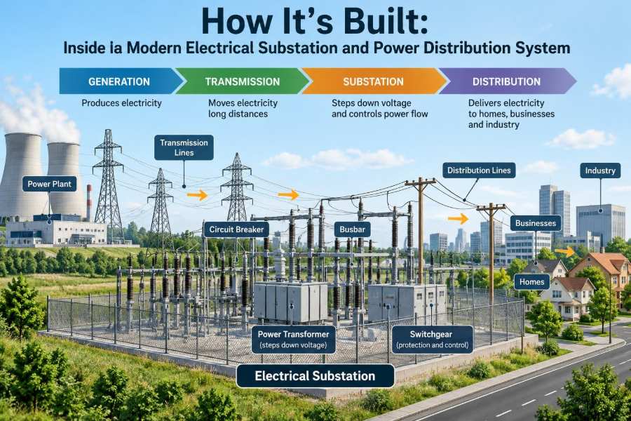
🗺️ From Power Plant to Wall Outlet
Electricity commonly begins at a generator voltage suitable for the generator itself, then passes through a step-up transformer. Raising voltage reduces current for the same power transfer, which reduces resistive heating losses in long conductors.
Transmission substations connect high-voltage lines and may step power down to subtransmission or distribution levels. Distribution substations then supply local feeders, which serve neighborhoods, commercial areas, and industrial customers.
The final reduction usually occurs closer to the customer. A pole-mounted or pad-mounted distribution transformer supplies the lower voltage used by a home or small business. Large facilities may receive medium-voltage service and own additional transformers on site.
📐 Why Voltage Changes Along the Way
The relationship P = VI is a useful starting point: power equals voltage times current in a simplified DC or power-factor-neutral view. For a given amount of power, increasing voltage permits lower current.
Conductor losses are approximately related to I²R. Cutting current has a disproportionately helpful effect on heating losses, which is why high voltages are practical for moving bulk power over long distances.
Higher voltage is not automatically better everywhere. It requires more insulation, greater clearances, more demanding equipment, and stricter safety design. Distribution systems balance efficiency against the cost and complexity of delivering usable power near loads.
🏗️ Choosing an Indoor, Outdoor, or Hybrid Site
Traditional outdoor substations use air as the main insulating medium. Their buses, disconnect switches, and insulators are visible, which can make inspection intuitive, but the site requires space and equipment must withstand weather and contamination.
Indoor substations place much of the equipment inside a building. They are useful where land is constrained, appearance matters, or equipment needs protection from severe environmental conditions.
Gas-insulated switchgear, often called GIS, encloses energized components in grounded metal housings with an insulating gas. It can greatly reduce footprint, but it is specialized equipment with different maintenance practices and environmental considerations related to insulating-gas handling.
🔩 The Busbar: The Electrical Backbone
A busbar is a robust conductor that forms a common connection point for circuits. In an outdoor yard it may be aluminum tube or stranded conductor; indoors it may be enclosed metal bus or rigid copper or aluminum bar.
The bus arrangement determines flexibility, reliability, cost, and the consequences of maintenance. A simple single-bus arrangement is economical, while more elaborate arrangements provide additional ways to keep circuits energized when one component is unavailable.
Busbars must withstand more than normal current. During a short circuit, electromagnetic forces can be severe. Their supports, spacing, and connections are designed for thermal heating and mechanical forces associated with prospective fault current.
🔀 Switchyards and the Paths Power Can Take
A switchyard is the outdoor area where transmission lines, buses, breakers, disconnects, transformers, and related equipment are interconnected. Its layout is a physical expression of the one-line diagram used by engineers and operators.
Each incoming line, transformer, or outgoing feeder is commonly called a bay. A bay contains the equipment needed to connect that circuit to the bus and isolate it safely when needed.
More alternate paths usually improve operating flexibility, but every additional breaker, disconnect, relay scheme, and control circuit adds cost and potential maintenance work. Good design matches the arrangement to the consequence of an outage rather than treating redundancy as universally necessary.
🧭 Reading a One-Line Diagram
A one-line diagram represents a three-phase power system with a single line and standardized symbols. It does not show every physical wire; it shows electrical relationships, equipment ratings, and normal switching states.
Learning to read one-lines is essential because field appearance can be misleading. Two conductors that look close together may belong to different circuits, while equipment separated by distance may be electrically connected through a bus section.
Before switching, operators use approved procedures, current system status, and site-specific drawings. A drawing is a planning tool, not proof that apparatus is in the expected position.
🔌 Transformers: Changing Voltage Without Changing Frequency
A power transformer transfers AC energy between windings through a changing magnetic field in a core. It changes voltage and current ratio while retaining the supply frequency.
In a step-down transformer, the secondary voltage is lower and the secondary current capability is higher. The reverse applies in a step-up transformer. The exact behavior depends on winding ratio, impedance, load, and control settings.
Large transformers are major assets because they combine magnetic cores, windings, insulation systems, cooling equipment, bushings, tap changers, monitoring devices, and protective interfaces in one unit. Their long replacement lead times often influence system planning.
🌡️ Cooling, Insulation, and Transformer Health
Transformer losses become heat. Many larger units use insulating mineral oil or another insulating fluid to transfer heat from internal parts toward radiators, fans, or pumps. The fluid also contributes to dielectric insulation.
Temperature matters because insulation ages faster when exposed to sustained high temperatures. Operators watch top-oil temperature, winding-temperature indicators, cooling equipment status, load, and sometimes dissolved gases in oil that may signal developing internal problems.
Oil-filled equipment also requires fire-risk planning, containment, drainage design, and environmental controls. The right approach depends on local conditions, equipment type, and applicable codes; it is never just a matter of placing a transformer on a concrete pad.
🎚️ Tap Changers and Voltage Regulation
Customer voltage should remain within an acceptable operating range despite changing load and feeder conditions. A transformer tap changer adjusts the effective turns ratio to help control voltage.
An on-load tap changer can change taps while the transformer is energized and carrying load. It uses a transition process designed to avoid interrupting current or shorting tap sections. Off-circuit tap settings require de-energization.
Tap control must be coordinated with capacitor banks, voltage regulators, distributed generation, and neighboring substations. Poor coordination can cause repeated operations or voltage swings rather than stable regulation.
💥 Circuit Breakers: Interrupting Fault Current
A circuit breaker can make, carry, and interrupt normal current and specified fault current. Unlike a simple switch, it is designed to open under demanding short-circuit conditions.
When breaker contacts separate, an arc can form. Medium- and high-voltage breakers use interruption media and mechanisms suited to their class, such as vacuum interrupters or gas-based interruption systems. The arc must be extinguished and the gap must regain dielectric strength quickly.
Breaker ratings must match the system’s prospective fault duty. Installing a breaker with an inadequate interrupting rating is a serious design error because the equipment may not safely clear the fault it is asked to interrupt.
🚪 Disconnect Switches Are Not Fault Breakers
Disconnect switches, also called isolators, provide a visible or verifiable isolation point for maintenance. They are generally operated after the circuit breaker has removed load and fault current.
The distinction is fundamental: a disconnect creates separation; a circuit breaker interrupts significant current. Some specialized switches can handle defined load-switching duties, but their permitted use is based on their rating and operating instructions.
Confusing these roles can produce dangerous arcing. Safe switching depends on the approved sequence, interlocks, status verification, and the actual equipment capabilities—not on assumptions based on appearance.
🛡️ Protective Relays: The System’s Decision Makers
Protective relays continuously analyze voltage, current, frequency, phase angle, and other signals. When measurements indicate a fault or abnormal condition, they issue a trip command to the appropriate breaker.
Modern numerical relays are programmable electronic devices, but their function follows enduring protection principles: operate quickly for faults in the protected zone, avoid operating for external faults, and coordinate with other devices.
Relay protection is deliberately layered. A primary scheme handles the expected fault, while backup protection acts if the primary relay, breaker, control circuit, or communications channel does not perform as intended.
🎯 Selectivity: Clearing Only What Is Necessary
Selectivity means isolating the smallest practical portion of the system affected by a fault. If a fault occurs on one neighborhood feeder, the desired result is usually to trip that feeder—not the whole substation.
Time-current coordination is one way to achieve this. Downstream protective devices may operate first for local faults, while upstream devices wait long enough to provide backup if the downstream device fails.
Protection cannot be perfectly selective in every situation. Very high fault currents, changing system configurations, limited measurement locations, and equipment failures create tradeoffs. Engineers document these conditions through fault studies and coordination studies.
📏 Instrument Transformers Make Measurement Practical
Power-system conductors may carry currents and voltages too large for meters, relays, and control equipment to connect to directly. Instrument transformers provide scaled, isolated signals.
A current transformer, or CT, produces a secondary current proportional to primary current. A voltage transformer, often called a VT or potential transformer, produces a proportional lower voltage. Relays use these signals to determine whether conditions are normal.
CT secondary circuits deserve special care. Opening a CT secondary while primary current flows can create hazardous high voltage and damage insulation. Procedures, shorting blocks, labeling, and trained personnel exist for a reason.
📡 SCADA and the Substation Control Room
Supervisory control and data acquisition, or SCADA, lets operators view alarms, measurements, equipment status, and trends from a control center. It may also permit remote commands under controlled operating practices.
A remote-control command travels through several layers: the control center, communications network, substation gateway or controller, relay or control logic, DC control circuit, and finally the breaker mechanism. Each layer needs clear status feedback and failure handling.
Automation improves awareness and response time, but it does not remove the need for sound operating judgment. Incorrect point mapping, stale telemetry, or misunderstood interlocks can turn apparently simple remote operations into serious events.
🔋 Station Batteries Keep Protection Alive
Substations commonly use a dedicated DC battery system with chargers, distribution panels, and monitoring. This source supplies protection relays, trip coils, control circuits, emergency lighting, and communications during loss of normal AC station service.
When a severe fault occurs, the AC system may be disturbed at precisely the moment a breaker must trip. Independent DC control power gives the protection system a reliable energy source to issue and complete that trip.
Battery condition is therefore operationally significant. Capacity testing, charger alarms, connection inspections, and documented maintenance help reveal degradation before a real emergency exposes it.
🌍 Grounding Turns Metalwork into a Safer Place
A substation grounding grid is a buried network of conductors bonded to structures, equipment frames, fences where required, cable shields, and neutral grounding systems. It provides a controlled path for fault and lightning currents.
The objective is not merely “zero volts.” During a fault, ground potential can rise. Design focuses on limiting dangerous touch and step voltages: the voltage between a person’s hands and feet, or between two points a person may step between.
Soil resistivity, fault magnitude, clearing time, surface material, and grid geometry all influence the result. Grounding design must be calculated and verified for the particular site rather than copied casually from another location.
🌩️ Lightning Arresters Limit Overvoltage Stress
Lightning and switching operations can create transient overvoltages that stress insulation. Surge arresters provide a lower-impedance path when voltage rises beyond their protective characteristic, helping limit the voltage that reaches protected equipment.
Arresters are placed near vulnerable equipment such as transformer terminals and line entrances. Lead length and grounding connections matter because fast transients are affected by inductance as well as ordinary resistance.
An arrester reduces risk; it does not make a site immune to every surge. Insulation coordination considers equipment withstand capability, expected surges, arresters, clearances, and the system configuration as a whole.
🧰 Distribution Feeders Carry Power into Communities
A distribution feeder leaves the substation at medium voltage and branches through an area to supply distribution transformers and larger customers. Feeders may be overhead, underground, or a combination of both.
Each feeder has thermal limits, voltage-drop behavior, protection devices, switching points, and a load profile that changes over hours and seasons. A feeder serving homes often peaks differently from one serving offices or manufacturing loads.
Feeder automation can identify a faulted section, isolate it, and restore unaffected sections through alternate ties when the network design permits. This can reduce outage extent, but only if protection, available capacity, and switching logic are properly coordinated.
🏘️ Overhead and Underground Distribution Compared
Overhead construction is generally accessible for inspection and repair, and it can be expanded relatively directly. It is, however, exposed to wind, vegetation, ice, vehicle contact, and other environmental hazards.
Underground cable removes many visible exposure risks and is often preferred in dense or appearance-sensitive areas. Fault location and repair can be more complex, excavation is disruptive, and cable thermal limits depend strongly on installation conditions.
| Feature | Overhead feeder | Underground feeder |
|---|---|---|
| Typical visibility | Components are readily visible | Most components are concealed |
| Common exposure | Weather, trees, external contact | Excavation damage, moisture-related issues, thermal constraints |
| Repair access | Often direct once the site is safe | May require locating, excavation, and cable work |
Neither approach is universally superior. Reliability depends on design, installation quality, maintenance, local environment, and the ability to isolate and restore sections.
🏢 Serving Large Commercial and Industrial Loads
Hospitals, campuses, factories, transit facilities, and data centers may require dedicated feeders or substations because their loads are large, sensitive, or both. They may have multiple utility supplies, standby generators, energy storage, or internal distribution networks.
Motor starting, harmonic-producing equipment, power-factor characteristics, and process continuity can shape the service design. A facility’s electrical engineer and utility planner must understand where responsibilities and protective boundaries meet.
Backup generation is not a substitute for coordination. If a facility can operate in island mode, its protection, grounding, transfer schemes, and synchronization controls must be engineered for that operating state.
☀️ Distributed Energy Changes Power Flow
Rooftop solar, battery systems, and small generators can cause power to flow from the distribution system toward the substation at certain times. Traditional distribution design often assumed one dominant direction: from substation to customer.
Reverse power flow can affect voltage regulation, protection sensitivity, fault contribution, and equipment loading. For example, a capacitor or regulator control strategy that works well with one-way flow may need revised settings when local generation is substantial.
Interconnection studies evaluate these issues for a specific feeder and resource. The result is not necessarily a rejection of distributed energy; it is a design process to maintain safe and dependable operation.
📊 Power Quality Is More Than Keeping the Lights On
A circuit can remain energized while still delivering poor power quality. Voltage sags, swells, interruptions, flicker, harmonics, and phase imbalance can affect sensitive equipment differently.
A brief voltage sag may be barely noticed by incandescent lighting but may reset an industrial drive or control system. Harmonics from nonlinear loads can increase heating or interfere with equipment if the system is not assessed and managed appropriately.
Monitoring helps distinguish a utility-side event from a facility-side issue. Useful records include waveform captures, event timestamps, voltage trends, and the operating status of major loads or generation at the time.
🧪 Testing Before Equipment Enters Service
Commissioning converts installed equipment into an operating system. It includes checking drawings, wiring, nameplates, mechanical operation, insulation condition, relay settings, communication paths, control logic, and alarms.
Protection testing should verify not only that a relay sees a simulated fault correctly, but also that the intended breaker trips, status is reported accurately, and unintended equipment does not operate. End-to-end tests may be needed for schemes involving communications.
Commissioning records matter later. They establish a baseline and help future teams understand what was installed, how it was configured, and what tests confirmed correct operation.
🔧 Maintenance Is Risk Management, Not Routine Ritual
Maintenance strategies range from scheduled inspection to condition-based work informed by temperature, oil analysis, breaker operations, partial-discharge indicators, battery data, and relay self-diagnostics.
Different equipment ages differently. A breaker with many fault interruptions may deserve attention even if it is not old, while a transformer may show early warning signs through changing fluid or temperature trends.
Maintenance must also account for outage risk. Taking equipment out of service can reduce redundancy, so planners evaluate system loading, switching options, weather exposure, and contingency actions before work begins.
🚧 Safety Depends on Procedure and Verification
Substations contain lethal voltages, stored mechanical energy, induced voltage, arc-flash hazards, and heavy equipment. Physical barriers and equipment ratings are necessary, but they are not enough without disciplined work practices.
A typical safe-work process includes identifying all sources, isolating equipment, applying protective grounding where required, locking and tagging controls according to the governing program, testing for absence of voltage with approved methods, and establishing boundaries.
Exact procedures vary by jurisdiction, employer, voltage class, and task. Only qualified personnel using approved site procedures should perform switching or maintenance; an educational diagram cannot replace a work permit, switching order, or field verification.
🧠 Common Misunderstandings to Avoid
- “A breaker protects everything downstream.” Protection has zones, settings, limitations, and backup relationships; a single device cannot solve every fault scenario.
- “Open means safe.” An open device may not provide the required isolation, and conductors can remain energized from another source or by induced voltage.
- “More redundancy always means more reliability.” Additional components and logic can improve options but also add failure modes and operational complexity.
- “Voltage is the only hazard.” Available fault current, arc energy, step and touch potential, stored energy, and unexpected backfeed also shape risk.
These distinctions are why power-system work relies on studies, drawings, operating rules, testing, and clear communication rather than intuition alone.
🧩 Seeing the Whole System
A substation works because its parts support one another. Transformers establish usable voltage levels; buses and switchgear create controllable paths; relays and breakers remove faults; grounding and arresters manage abnormal energy; batteries and controls preserve the ability to act.
Distribution extends that design logic outward. Feeders deliver power, local transformers make it usable, and coordinated protection limits the area affected when equipment or conductors fail.
The core principle is controlled energy: a reliable power system does not merely move electricity efficiently—it measures, directs, regulates, and isolates it deliberately under both normal and abnormal conditions.
Once you can connect the one-line diagram to the equipment in the yard and the loads beyond it, a substation stops looking like a maze of metal. It becomes a readable, engineered chain of decisions that keeps modern life powered safely and dependably. ⚡🏗️🔌