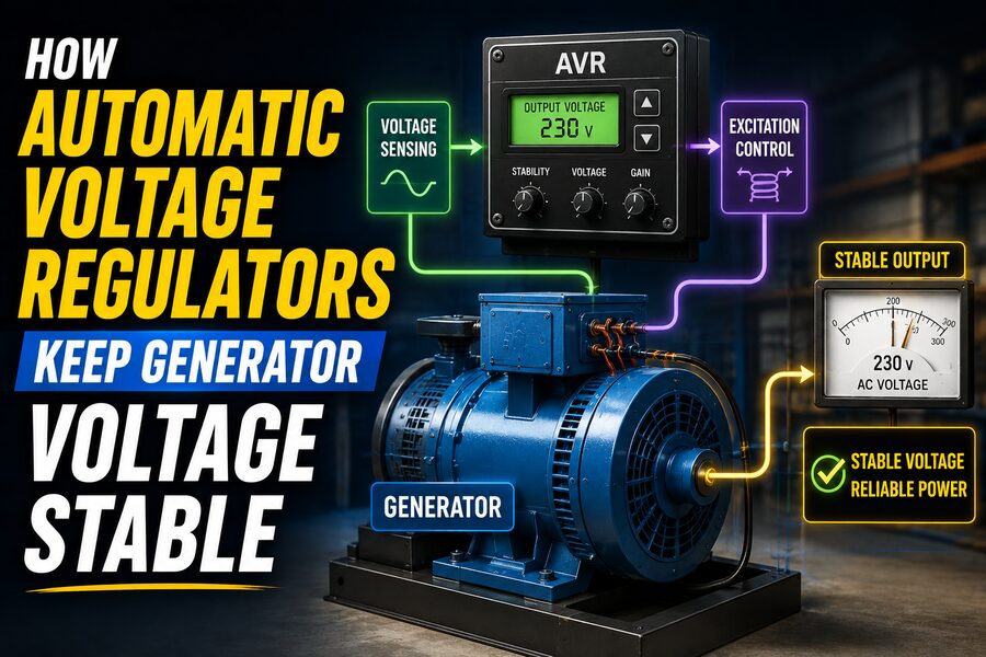

Electric generators are expected to provide a dependable voltage even when the electrical load changes dramatically. A generator may be supplying only a few lights one moment and then suddenly be asked to power large motors, pumps, compressors, heaters, or industrial equipment. Without some form of automatic control, these changing loads could cause the generator’s output voltage to rise or fall significantly. 🔌🏭
The device responsible for keeping that voltage under control is the Automatic Voltage Regulator, commonly called an AVR.
An AVR continuously monitors the generator’s output voltage and adjusts the electrical excitation of the generator so that the terminal voltage remains close to a desired value.
In simplified form:
Voltage falls ➡️ AVR increases excitation
Voltage rises ➡️ AVR decreases excitation
This feedback process happens rapidly and continuously, helping the generator deliver stable electrical power under changing operating conditions. ⚙️⚡
🧠 Why Generator Voltage Changes
A synchronous generator produces electricity by rotating a magnetic field relative to stationary windings.
The generated voltage depends on several important factors, including:
- Rotor speed
- Magnetic field strength
- Generator design
- Electrical load
- Power factor
- System conditions
If the engine or turbine driving the generator maintains nearly constant speed, the AVR can regulate voltage primarily by controlling the strength of the generator’s magnetic field.
When electrical load changes, current through the generator changes as well.
This affects internal voltage drops and magnetic behavior inside the machine.
Without regulation, the terminal voltage could move outside acceptable limits.
🧲 The Role of Excitation
Most synchronous generators need a magnetic field on their rotor.
This field is produced using excitation current.
Excitation current flows through the rotor field winding and creates magnetic flux.
A stronger rotor field generally produces a higher generated voltage.
A weaker field produces a lower voltage.
Therefore, the AVR controls generator voltage by adjusting excitation.
Conceptually:
More field current → stronger magnetic field → higher generator voltage
Less field current → weaker magnetic field → lower generator voltage
This makes excitation the main control lever available to the voltage regulator. 🎛️
🔍 How the AVR Knows the Voltage
The AVR continuously measures the generator’s terminal voltage.
In many systems, this voltage is reduced to a safe level using sensing circuits or instrument transformers.
The regulator compares the measured value with an internal reference voltage.
Suppose the generator is designed to maintain:
400 V
The AVR may continuously compare:
Measured voltage = 392 V
with:
Target voltage = 400 V
The regulator detects an error of:
8 V low
It then increases excitation to raise the output voltage.
This is a classic closed-loop feedback control system. 🔄
🔄 Understanding the Feedback Loop
The regulation process can be described as:
Generator output voltage
⬇️
Voltage sensing
⬇️
Comparison with reference
⬇️
AVR calculates correction
⬇️
Excitation changes
⬇️
Generator magnetic field changes
⬇️
Output voltage moves toward target
The new voltage is measured again, and the process repeats continuously.
This feedback loop allows the generator to automatically correct disturbances without requiring an operator to manually adjust the field current every time the load changes.
📉 What Happens When Load Suddenly Increases?
Imagine a generator supplying a building.
Initially, the generator powers only lighting and small equipment.
Then a large electric motor starts. 🏭
The motor may draw a high starting current.
This additional current causes greater internal voltage drop inside the generator.
As a result, terminal voltage may temporarily fall.
The AVR detects the drop.
It responds by increasing current in the excitation system.
The stronger rotor magnetic field raises the generated voltage, helping restore the terminal voltage toward its setpoint.
The sequence is:
Large load connects
⬇️
Generator voltage dips
⬇️
AVR senses low voltage
⬇️
Excitation increases
⬇️
Voltage recovers
This entire response may occur in fractions of a second.
📈 What Happens When Load Is Removed?
The opposite occurs when a large load suddenly disconnects.
Suppose an industrial heater drawing substantial current switches off.
The generator’s internal voltage drop decreases immediately.
Terminal voltage may rise above the desired level.
The AVR detects the increase and reduces excitation.
This weakens the rotor field and brings the terminal voltage back toward normal.
So the regulator works in both directions:
Low voltage → increase excitation
High voltage → reduce excitation
⚙️ Main Components of an AVR System
A practical voltage regulation system may include several functional sections.
🔹 Voltage Sensing Circuit
This measures generator terminal voltage.
For three-phase systems, the regulator may sense one phase or multiple phases depending on the design.
🔹 Reference Circuit
The AVR stores a desired voltage level against which the measured voltage is compared.
🔹 Error Amplifier
The difference between measured and desired voltage creates an error signal.
The regulator amplifies and processes this signal.
🔹 Control Circuit
The control electronics determine how strongly the excitation should be adjusted.
🔹 Power Output Stage
This stage provides the required current or voltage to the exciter field or generator field system.
Together, these components form an automatic control loop. 🧩
🌀 What Is an Exciter?
Large generators often use a separate device called an exciter to supply rotor field current.
The AVR controls the exciter rather than directly supplying the generator’s main field current.
A simplified arrangement might be:
AVR
⬇️
Exciter field
⬇️
Exciter output
⬇️
Main generator rotor field
⬇️
Generator output voltage
This arrangement allows relatively small electronic control signals to regulate much larger excitation power.
🔄 Brushless Excitation Systems
Many modern generators use brushless excitation.
In older systems, rotor field current could be supplied through slip rings and carbon brushes.
Brushes wear over time and require maintenance.
A brushless exciter avoids continuous sliding electrical contact.
Typically, the exciter generates AC electricity on the rotating assembly.
Rotating diodes then rectify this AC into DC for the main rotor field.
The AVR controls the stationary exciter field.
Advantages can include:
- Lower maintenance
- Improved reliability
- No brush wear
- Better suitability for continuous operation
Brushless excitation is common in industrial and standby generators. ⚡
🔌 Self-Excited Generators
Some generators obtain the AVR’s power from the generator’s own output terminals.
This is called self-excitation.
The AVR uses part of the generated electrical output to supply the excitation system.
This arrangement can be simple and economical.
However, during severe faults or heavy motor starting, terminal voltage may fall significantly.
Because the AVR’s own power source also falls, excitation capability may be reduced exactly when additional field strength is needed.
This is why other excitation arrangements are sometimes used for demanding applications.
🧲 Permanent Magnet Generator Excitation
Some generators use a small Permanent Magnet Generator, or PMG, mounted on the same shaft.
The PMG provides a dedicated power source for the AVR.
Because the PMG is independent of the main generator’s terminal voltage, the AVR can continue receiving strong control power even when the main voltage temporarily collapses.
PMG excitation can improve:
- Motor-starting performance
- Fault-current support
- Voltage recovery
- Regulation under nonlinear loads
This makes PMG systems attractive for generators supplying demanding industrial loads. 🏭
⚡ Why Motor Starting Is Difficult
Large induction motors may draw several times their normal operating current when starting.
For example, a motor with a normal current of:
100 A
could briefly draw:
500–700 A
during startup, depending on motor and starting method.
This surge places heavy demand on the generator.
The terminal voltage may dip significantly.
A responsive AVR helps restore voltage by rapidly increasing excitation.
However, the generator itself must also have sufficient size and electromagnetic capability.
An AVR cannot compensate for a generator that is fundamentally too small for the starting load.
🎛️ Voltage Setpoint Adjustment
Many AVR systems allow the desired generator voltage to be adjusted.
This may be done using:
- A local potentiometer
- Digital control settings
- A remote voltage-adjust input
- A generator control panel
Suppose the generator’s nominal line voltage is:
415 V
The operator might be able to make small adjustments around that value.
The AVR then treats the selected level as the new reference.
Voltage adjustment is normally limited to a safe range.
📊 What Is Voltage Regulation?
Generator voltage regulation is often expressed as the change in terminal voltage between operating conditions.
A well-regulated generator might maintain voltage within approximately a small percentage of the setpoint under normal loads.
For example, if a 400 V generator maintains output between:
396 V and 404 V
the variation is quite small.
The exact performance depends on generator design, AVR quality, load type, speed stability, and operating conditions.
Good voltage regulation protects connected equipment and improves overall power quality.
🔺 Reactive Power and Generator Voltage
In AC systems, loads do not always consume only real power.
They may also draw reactive power.
Induction motors and transformers often require reactive power to establish magnetic fields.
Reactive current affects generator voltage strongly.
When a generator supplies a highly inductive load, terminal voltage tends to fall more than it would with a purely resistive load.
The AVR compensates by increasing excitation.
This relationship between excitation and reactive power becomes especially important when generators operate in parallel.
🔗 Generators Operating in Parallel
Large facilities may operate several generators together.
When synchronous generators share a common electrical bus, voltage regulation becomes more complicated.
The generators must properly share:
- Real power
- Reactive power
Engine speed or governor control primarily influences real-power sharing.
Excitation and AVR behavior primarily influence reactive-power sharing and voltage.
If one generator is overexcited, it may supply excessive reactive power compared with the others.
To prevent this, regulators may use special control methods such as:
- Droop compensation
- Cross-current compensation
- Reactive-power control
- Power-factor control
These techniques help multiple machines operate together stably. 🤝⚡
📉 What Is Voltage Droop?
When generators operate in parallel, a completely rigid voltage regulator can sometimes make reactive-power sharing unstable.
Voltage droop intentionally allows the regulated voltage setpoint to decrease slightly as reactive load increases.
This encourages generators to share reactive power more predictably.
Droop is therefore not necessarily a defect.
In parallel-generation systems, it can be an intentional control characteristic.
🔄 AVR vs. Governor
A generator usually has two major automatic control systems:
⚡ AVR
Controls:
Voltage and excitation
🌀 Governor
Controls:
Engine or turbine speed and frequency
The governor adjusts mechanical input power to maintain rotational speed.
The AVR adjusts magnetic excitation to maintain electrical voltage.
For example:
If electrical load increases, the generator tends to slow down.
The governor increases fuel or turbine input.
At the same time, the voltage may fall.
The AVR increases excitation.
These two systems work together to keep the electrical output stable. ⚙️
🕒 Frequency and Voltage Are Different
People sometimes assume the AVR controls frequency.
It generally does not.
Frequency primarily depends on generator rotational speed.
For a synchronous generator, frequency is related to speed by:
f = P × N / 120
where:
f= electrical frequencyP= number of polesN= rotational speed in rpm
For example, a four-pole generator producing 50 Hz runs at approximately:
1,500 rpm
The governor maintains that speed.
The AVR handles voltage.
📈 AVR Response Speed
A voltage regulator must respond quickly enough to load changes but not so aggressively that the system becomes unstable.
If regulation is too slow:
- Voltage dips may last too long.
- Equipment may malfunction.
- Motors may struggle to start.
If control is too aggressive:
- Voltage may overshoot.
- The system may oscillate.
- Excitation may repeatedly rise and fall.
Engineers therefore tune the AVR’s dynamic response.
This is a classic feedback-control problem involving gain, stability, and damping. 🎯
🌊 What Is Voltage Hunting?
If an AVR is poorly tuned, generator voltage may repeatedly oscillate above and below the target.
This behavior is sometimes described as hunting.
For example:
400 V → 420 V → 385 V → 412 V → 392 V…
Instead of settling smoothly, the regulator continuously overcorrects.
Proper controller tuning prevents this behavior.
Modern digital AVRs can use sophisticated control algorithms to produce a fast but stable response.
🧮 Proportional, Integral, and Derivative Concepts
Some voltage regulators use control concepts related to PID control.
A controller may respond to:
Proportional Error
How far the voltage currently differs from the setpoint.
Integral Error
How long a persistent voltage error has existed.
Derivative Behavior
How rapidly the error is changing.
Actual commercial AVR algorithms vary, but these feedback principles help explain how regulators balance fast correction with stability.
🛡️ Under-Excitation Protection
Generator excitation cannot be reduced indefinitely.
If a synchronous generator becomes excessively underexcited, it can operate in undesirable regions that may lead to:
- Heating
- Stability problems
- Excessive reactive-power absorption
Large generator systems may therefore include under-excitation limiters.
These controls prevent the AVR from commanding unsafe operating conditions.
🔥 Over-Excitation Protection
Too much excitation can also be dangerous.
High rotor field current causes heating in field windings.
Excessive magnetic flux can also stress generator and transformer cores.
Large excitation systems may include:
- Over-excitation limiters
- Field-current limiters
- Volt-per-hertz protection
These safeguards keep voltage regulation within the physical capabilities of the generator.
⚠️ What Is V/Hz Protection?
Magnetic equipment is sensitive not only to voltage but also to the ratio of voltage to frequency.
If frequency drops while voltage remains high, magnetic flux can become excessive.
This is why regulators may reduce voltage when generator speed falls significantly.
For example, during engine startup or shutdown, the AVR may follow an under-frequency roll-off characteristic.
As frequency decreases below a threshold, the regulator intentionally lowers voltage.
This protects the generator and connected magnetic equipment from over-fluxing.
🌀 Under-Frequency Roll-Off
Suppose a 50 Hz generator begins slowing below its normal speed because the engine is overloaded.
If the AVR attempted to maintain full voltage regardless of frequency, magnetic components could become overstressed.
Instead, under-frequency protection may reduce the voltage setpoint.
Conceptually:
Normal frequency → full rated voltage
Low frequency → reduced voltage
This allows the voltage-frequency ratio to remain safer.
🔌 Nonlinear Loads and AVRs
Modern generators increasingly supply nonlinear loads such as:
- Variable-frequency drives
- UPS systems
- Computers
- LED power supplies
- Rectifiers
These loads may draw distorted current waveforms.
Distorted current can create harmonic voltage distortion.
An AVR can regulate overall voltage magnitude, but it cannot completely eliminate every waveform distortion caused by the generator’s impedance and nonlinear load currents.
Generator sizing and alternator design therefore remain important.
🖥️ Digital Automatic Voltage Regulators
Older AVRs often relied primarily on analog electronics.
Modern regulators increasingly use digital processors.
Digital AVRs can provide:
- Precise voltage sensing
- Programmable control
- Event logging
- Communication interfaces
- Protection functions
- Reactive-power control
- Remote monitoring
Engineers can sometimes configure them through software instead of adjusting physical potentiometers.
This makes integration with modern generator management systems much easier. 💻
🏥 Why Voltage Stability Matters
Stable generator voltage is critical in facilities such as:
- Hospitals
- Data centers
- Factories
- Airports
- Telecommunications sites
- Emergency services
Sensitive equipment may not tolerate large voltage swings.
Low voltage can cause:
- Motors to draw excessive current
- Contactors to drop out
- Electronics to malfunction
High voltage can:
- Damage insulation
- Overheat equipment
- Shorten component life
The AVR helps keep emergency and prime-power systems within acceptable voltage limits. 🏥⚡
🏭 Industrial Example
Imagine a 500 kVA generator powering a manufacturing facility.
Initially, the connected load is:
150 kVA
A large compressor then starts.
The load rises rapidly and motor starting current causes terminal voltage to fall from:
400 V to 350 V
The AVR immediately senses the reduction.
It increases exciter output, strengthening the rotor field.
Voltage may then recover toward:
400 V
as the motor accelerates and starting current falls.
Without the AVR, the voltage dip could remain much deeper or persist longer, potentially affecting other equipment in the plant.
🔧 Why an AVR Cannot Fix Everything
An AVR is powerful, but it has limits.
It cannot compensate indefinitely for:
- An undersized generator
- Severe engine speed loss
- Major electrical faults
- Broken excitation components
- Excessive overload
- Incorrect wiring
If a generator rated at 100 kVA is asked to supply a 300 kVA load, increasing excitation will not magically create enough mechanical or electrical capacity.
Proper generator sizing remains essential.
🧯 Common AVR Problems
Voltage-regulation problems can result from:
- Failed sensing connections
- Damaged exciter windings
- Faulty rotating diodes
- Loose terminals
- Incorrect regulator adjustment
- Failed electronic components
- Loss of residual magnetism in some systems
- Overheating
Symptoms may include:
- No output voltage
- Excessively high voltage
- Low voltage
- Unstable voltage
- Slow recovery after load changes
Because generator systems can contain dangerous voltages and rotating machinery, troubleshooting should be performed by qualified personnel. ⚠️
🔍 Maintenance and Testing
Generator maintenance may include checking:
- Terminal voltage
- Voltage regulation under load
- Excitation current
- Wiring and connectors
- Insulation condition
- Diodes
- AVR settings
Load-bank testing is often used to verify generator performance.
A load bank applies controlled electrical load while technicians observe:
- Voltage stability
- Frequency
- Temperature
- Engine behavior
- AVR response
This helps identify problems before the generator is needed during an emergency.
🌐 Generator Voltage in Microgrids
Modern microgrids may combine:
- Diesel generators
- Solar inverters
- Battery systems
- Grid connections
Voltage regulation becomes a coordinated task.
The generator AVR may need to interact with inverter controls and microgrid energy-management systems.
As distributed energy systems become more common, generator excitation control remains an important part of maintaining stable power networks. 🌞🔋⚡
🧠 The Physics Behind AVR Control
The fundamental principle is electromagnetic induction.
The voltage generated in an alternator is related to:
- Magnetic flux
- Rotational speed
- Winding configuration
If speed remains approximately constant, changing magnetic flux provides an effective way to change voltage.
The AVR therefore modifies field current.
That changes rotor magnetic flux.
The changing flux changes generated electromotive force.
In simplified terms:
Field current ↑ → magnetic flux ↑ → generated voltage ↑
and:
Field current ↓ → magnetic flux ↓ → generated voltage ↓
This is why such a relatively small control system can regulate the output of a generator producing hundreds of kilowatts or even much more.
🚀 Final Thoughts
An Automatic Voltage Regulator keeps generator voltage stable by continuously measuring the electrical output, comparing it with a desired reference, and adjusting the generator’s excitation system.
When a heavy load causes voltage to fall, the AVR strengthens the rotor’s magnetic field.
When load removal causes voltage to rise, it reduces the magnetic field.
This happens automatically through a fast feedback loop. 🔄⚡
Modern AVR systems may also provide far more than basic voltage control. They can support:
- Reactive-power sharing
- Generator paralleling
- Excitation limiting
- Under-frequency protection
- Remote monitoring
- Digital diagnostics
Yet the core principle remains simple:
Sense the voltage → compare it with the target → adjust excitation → measure again.
The AVR works alongside the engine governor, which controls speed and frequency, to keep generator output stable under changing electrical demand.
Whether the generator powers a hospital during a blackout, an industrial plant, a remote telecommunications site, or an entire microgrid, voltage stability is essential for protecting connected equipment and maintaining dependable electrical service.
The AVR is therefore one of the generator’s most important control systems—quietly making thousands of corrections so that the voltage at the terminals remains steady even while the electrical load is constantly changing. ⚡🏭🔌✨