
A ventilation fan starts at full speed every morning, even when a building is nearly empty. A conveyor jolts its load into motion. A pump throttles water with a valve while its motor continues consuming power at maximum speed.
These are familiar situations in factories, commercial buildings, water systems, and workshops. The motor may be mechanically sound, yet the process is being controlled inefficiently or roughly because the motor has only one practical speed: the speed set by the power line.
A variable frequency drive, usually called a VFD, changes that relationship. It uses power electronics and software to supply an AC motor with voltage and frequency tailored to the work it must do.
Understanding what happens inside a VFD makes its capabilities—and its limits—much easier to apply safely. It also explains why a drive can save energy in one machine, improve control in another, and create unexpected electrical problems if installed carelessly.
⚙️ The Basic Job of a Variable Frequency Drive
A VFD controls the speed of an AC motor by controlling the electrical frequency supplied to it. It can also manage acceleration, deceleration, direction, current limits, and protective responses.
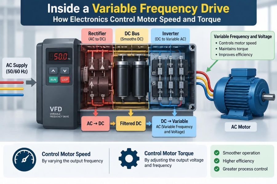
The usual power path is simple in principle: fixed-frequency AC enters the drive, is converted to DC, and is then reconstructed as variable-frequency AC for the motor. The reconstruction is highly controlled, which is where the drive earns its flexibility.
🧲 Why Frequency Sets Motor Speed
Most VFD applications use induction motors. Their rotating magnetic field has a speed related to supply frequency and motor pole count. This is called synchronous speed.
A four-pole motor supplied at 50 Hz has a synchronous speed of 1,500 revolutions per minute; at 60 Hz, it is 1,800 rpm. The rotor runs slightly below that field speed under load. That difference, called slip, is necessary for an induction motor to produce torque.
🔌 The Fixed-Speed Limitation of Mains Power
Utility power normally arrives at a fixed frequency, commonly 50 or 60 Hz depending on the region. Connecting an induction motor directly to it therefore produces a speed that changes only modestly with load.
Mechanical devices have traditionally handled unwanted output with dampers, valves, gearboxes, clutches, or on-off cycling. Those methods can be appropriate, but they do not give the motor itself finely adjustable speed.
🔄 AC Becomes DC in the Rectifier
The first major stage inside a typical VFD is the rectifier. A diode bridge commonly converts incoming three-phase AC into pulsating DC. Some drives use controlled or active rectifiers instead.
Diodes allow current to flow in one direction, so the negative portions of the AC waveform are redirected. The result is not yet smooth enough for the inverter, but it is now a DC supply that can be stored and shaped.
🪣 The DC Bus Stores Energy
After rectification, capacitors in the DC bus, or DC link, smooth much of the voltage ripple and store energy briefly. Inductors or DC chokes may also be included to reduce ripple and moderate current distortion.
Think of the DC bus as an electrical reservoir between the supply and the motor. It decouples the input waveform from the rapidly switched output waveform, though it is not unlimited storage.
⚡ The Inverter Rebuilds Three-Phase Power
The inverter is the stage that creates the adjustable motor supply. It uses high-speed semiconductor switches, usually insulated-gate bipolar transistors or IGBTs in many conventional industrial drives.
By switching DC bus voltage onto each motor phase in a carefully timed sequence, the inverter synthesizes three output phases. Their effective frequency determines rotating-field speed, while their effective voltage is managed to support motor flux and torque.
📐 PWM Creates a Useful Sine-Like Output
VFD output is not a smooth analog sine wave at the switching devices. It is a train of fast voltage pulses. This method is called pulse-width modulation, or PWM.
Within each short switching interval, the drive varies how long a phase is connected to the positive or negative DC bus. The motor’s inductance averages much of this pulse pattern into current that is approximately sinusoidal, producing a rotating magnetic field.
The fast edges still matter. They contribute to insulation stress, electromagnetic interference, and cable-related effects that must be considered in real installations.
🎚️ Voltage Must Follow Frequency
Lowering frequency without lowering voltage can over-magnetize the motor core. Raising frequency without sufficient voltage weakens the magnetic flux and reduces available torque.
For basic control below the motor’s base speed, a drive follows an approximate volts-per-hertz relationship. If frequency is reduced roughly in proportion to voltage, the air-gap flux can remain near its intended value.
At very low speed, resistance drops in the stator become more significant. Drives may add voltage boost or use more advanced control to maintain useful torque.
💪 What Motor Torque Really Depends On
Torque is the twisting force available at the shaft. In an induction motor, it arises from the interaction between the stator’s rotating magnetic field and currents induced in the rotor.
Torque depends on flux, rotor conditions, motor parameters, and the difference between field speed and rotor speed. A VFD does not create unlimited torque; it manages voltage, frequency, and current so the motor can produce appropriate torque within its electrical and thermal limits.
🚀 Starting Without the Inrush Shock
A motor connected directly across the line can draw a large starting current while it accelerates. That may cause voltage dip, mechanical shock, and stress on couplings or driven equipment.
A VFD starts by commanding low frequency and controlled voltage, then ramps upward. It monitors current and can limit acceleration if demand exceeds its programmed capability. This produces a controlled start rather than an abrupt application of full line voltage.
🏃 Speed, Load, and the Acceleration Ramp
A speed command does not instantly change a loaded motor’s actual speed. The drive must supply enough torque to overcome load torque and accelerate the rotating inertia of the motor and machine.
An overly short acceleration time causes overcurrent trips or mechanical strain. An overly long ramp can be impractical in production. Good setup begins with the load: a lightly loaded fan, a loaded conveyor, and a high-inertia centrifuge need very different ramp profiles.
🛑 Deceleration Turns Motion into Electrical Energy
When a drive slows a motor faster than the load would naturally coast, the motor can act as a generator. Energy returns from the spinning system into the DC bus, raising its voltage.
That is why a drive may trip on DC-bus overvoltage during aggressive deceleration. The stored energy needs somewhere to go; simply commanding a lower speed does not make inertia disappear.
🔥 Braking Resistors and Regenerative Drives
A dynamic braking resistor gives excess DC-bus energy a controlled path to heat. A braking transistor switches the resistor into circuit when bus voltage rises above a threshold.
For frequent or substantial braking, a regenerative front end can return energy to the AC supply rather than dissipating it. This adds cost and design complexity, but can suit elevators, test stands, cranes, and other applications with recurring overhauling loads.
📈 The Constant-Torque and Variable-Torque Difference
Load type strongly affects drive selection. Conveyors, mixers, extruders, positive-displacement pumps, and many hoists generally require substantial torque across their operating speed range. These are commonly described as constant-torque loads.
Fans and centrifugal pumps are usually variable-torque loads. Their torque demand falls rapidly as speed falls, so speed reduction can greatly reduce required shaft power. This is why VFDs are especially valuable for flow control in suitable fan and pump systems.
| Load example | Typical torque behavior | Practical implication |
|---|---|---|
| Conveyor | Near constant torque | Needs strong low-speed starting torque |
| Centrifugal fan | Torque rises strongly with speed | Lower speed can substantially reduce power demand |
| Hoist | Depends on load direction | May require braking or regeneration |
🌀 The Fan and Pump Affinity Laws
For a centrifugal fan or pump operating in a similar system, flow is approximately proportional to speed, pressure is approximately proportional to speed squared, and power is approximately proportional to speed cubed.
These are engineering approximations, not a promise for every installation. System curves, fluid conditions, impeller geometry, and operating point matter. Still, they explain why reducing fan speed can be more efficient than throttling flow with a damper.
🧠 Scalar Control and Vector Control
Basic volts-per-hertz control, often called scalar control, commands frequency and voltage using a predefined relationship. It works well for many pumps, fans, and uncomplicated speed-control tasks.
Vector control estimates or measures motor magnetic conditions and separates torque-producing current from flux-producing current. It can provide tighter speed regulation, stronger low-speed torque, and faster response, particularly where load changes quickly.
More sophisticated control does not remove the need for correct motor data and sensible mechanical design.
📍 Sensorless Control Versus Encoder Feedback
Many drives estimate motor speed from voltage, current, and a motor model; this is called sensorless vector control. It avoids fitting a shaft sensor and is effective for many industrial duties.
Some applications need more accurate low-speed operation or precise position-related control. An encoder attached to the motor shaft provides actual motion feedback. Elevators, coordinated machinery, and demanding tension systems may justify that additional hardware.
🧾 Motor Nameplate Data Is Not Optional
Commissioning a VFD begins with entering the motor’s rated voltage, current, frequency, speed, and power as applicable. These values allow the drive’s control and protection functions to make meaningful decisions.
A common mistake is copying settings from a previous installation or assuming a motor’s frame size reveals its rating. Incorrect data can lead to poor torque performance, nuisance faults, inadequate overload protection, or overheating.
🌡️ Low-Speed Cooling Can Limit Continuous Torque
A standard motor’s shaft-mounted fan slows with the motor. At low speed, the motor may produce useful torque electrically while receiving much less cooling air.
Continuous low-speed, high-torque duty may require a separately powered blower, a motor designed for inverter duty, derating, or a larger motor. The correct answer depends on the motor’s thermal design, ambient temperature, load cycle, and manufacturer data.
🧵 Long Motor Cables Change the Electrical Picture
Fast PWM voltage edges travel along motor cables. On long leads, wave reflections can increase peak voltage at the motor terminals beyond what the drive’s nominal output voltage suggests.
Older motors and motors with insulation not intended for inverter service can be especially vulnerable. Output reactors, dv/dt filters, or sine-wave filters may be selected based on cable length, voltage class, motor insulation, and the drive manufacturer’s guidance.
📻 Harmonics and Input Power Quality
A standard diode rectifier draws current in pulses rather than smoothly throughout the AC cycle. Those pulses create harmonic currents in the supply system.
Harmonics can affect transformers, generators, conductors, and other equipment, especially where many drives share a weak electrical source. Line reactors, DC chokes, passive filters, active harmonic filters, or active-front-end drives are possible mitigation tools; the right choice depends on a system-level assessment.
🛡️ Grounding, Shielding, and Electromagnetic Interference
VFD switching can create electromagnetic interference, or EMI. Poor grounding and cable routing can turn a sound motor-control installation into a source of noise in sensors, communication systems, or control circuits.
Practical measures include short, low-impedance protective-earth connections, correctly terminated shielded motor cable where required, physical separation between power and sensitive signal wiring, and installation practices specified by the equipment manufacturers.
Shielding is not a substitute for grounding. Both are part of controlling high-frequency current paths.
🧯 Protection Functions Need Real-World Coordination
Drives commonly monitor overcurrent, ground faults, phase conditions, overheating, DC-bus voltage, motor overload models, and communication faults. These functions help protect equipment, but they do not replace all upstream protection or machine safety systems.
Fuses, circuit breakers, contactors, emergency stops, safety relays, and disconnecting means must be chosen and wired for the specific installation. A VFD command to stop is not automatically a safety-rated removal of hazardous motion.
🔧 Selecting Drive Ratings Beyond Kilowatts
Matching a drive to motor kilowatts or horsepower is only the starting point. The drive’s output current rating, overload duty, supply voltage, ambient temperature, enclosure, altitude, expected switching frequency, and load profile all matter.
- Use the drive’s heavy-duty rating for demanding acceleration or sustained overload requirements.
- Check whether the motor is suitable for inverter operation at the planned voltage and speed range.
- Consider enclosure protection against dust, water, corrosive air, and heat.
- Confirm that supply capacity and fault protection suit the chosen drive.
🧰 Parameters That Deserve Careful Setup
A factory-default drive is not a finished application. Minimum and maximum speeds, acceleration and deceleration times, current limits, motor protection settings, stop mode, and control source should be reviewed deliberately.
For example, a pump may need a minimum speed to maintain lubrication or stable flow. A conveyor may need a controlled ramp to prevent product from shifting. A fan may need to avoid resonant speeds that create vibration.
⚠️ Common Installation Mistakes
Some faults are caused less by failed electronics than by assumptions made during design or commissioning. Avoiding them saves considerable troubleshooting time.
- Using a general-purpose motor continuously at low speed without checking cooling.
- Adding a contactor between drive and motor that opens while the drive is actively producing output.
- Using an undersized drive because nominal motor power appears to match.
- Running unshielded motor cable beside low-level analog or communication wiring.
- Ignoring driven-equipment limits, such as pump minimum flow or gearbox speed ratings.
🔍 Troubleshooting by Following Energy Flow
A useful troubleshooting sequence follows the same path as the power: verify supply conditions, examine DC-bus behavior, inspect output and motor connections, then assess the mechanical load. Do not begin by randomly changing parameters.
An overcurrent fault during acceleration may indicate a ramp that is too short, a jammed load, incorrect motor data, a damaged cable, or a motor issue. A bus overvoltage fault during deceleration points more naturally toward excessive regenerative energy or an unsuitable stopping ramp.
Measurements around drives require appropriate instruments and training. PWM output can mislead ordinary meters, and stored energy in the DC bus remains hazardous after power is removed.
🧑🏭 A Practical Conveyor Example
Imagine a packaging conveyor that must run slowly during setup, accelerate smoothly for production, and stop without tipping lightweight containers. A direct-on-line motor starter can start and stop it, but offers limited control.
A VFD can apply low-speed vector control during setup, use a tuned acceleration ramp, enforce a current limit if the belt binds, and coordinate speed with upstream equipment. The drive improves the process only if the conveyor’s gearbox, belt, guarding, and safety system are also suitable for the chosen speeds.
📚 Reading a VFD System as One Machine
A drive is not merely an electronic box placed between the supply and motor. It is part of a system that includes electrical distribution, cables, a motor, mechanics, process requirements, controls, and safety functions.
That perspective prevents simplistic conclusions. A VFD may reduce throttling losses in a pump system, yet be a poor solution if minimum-flow requirements are ignored. It may deliver excellent low-speed torque, yet overheat a motor that lacks cooling.
✅ The Core Principle to Remember
The central idea is straightforward: a VFD rectifies fixed-frequency AC to DC, then uses a PWM inverter to create three-phase power with controlled frequency and voltage. Frequency establishes the rotating field’s speed, while voltage and current control support the magnetic flux and torque needed by the load.
Everything else follows from applying that principle responsibly: match the drive to the load, respect motor thermal limits, provide a path for braking energy, manage cable and harmonic effects, and commission parameters from actual machine requirements.
A variable frequency drive gives motors adaptable behavior, but dependable speed and torque control comes from treating the electronics, motor, load, and installation as one engineered system. ⚡🔧🏭