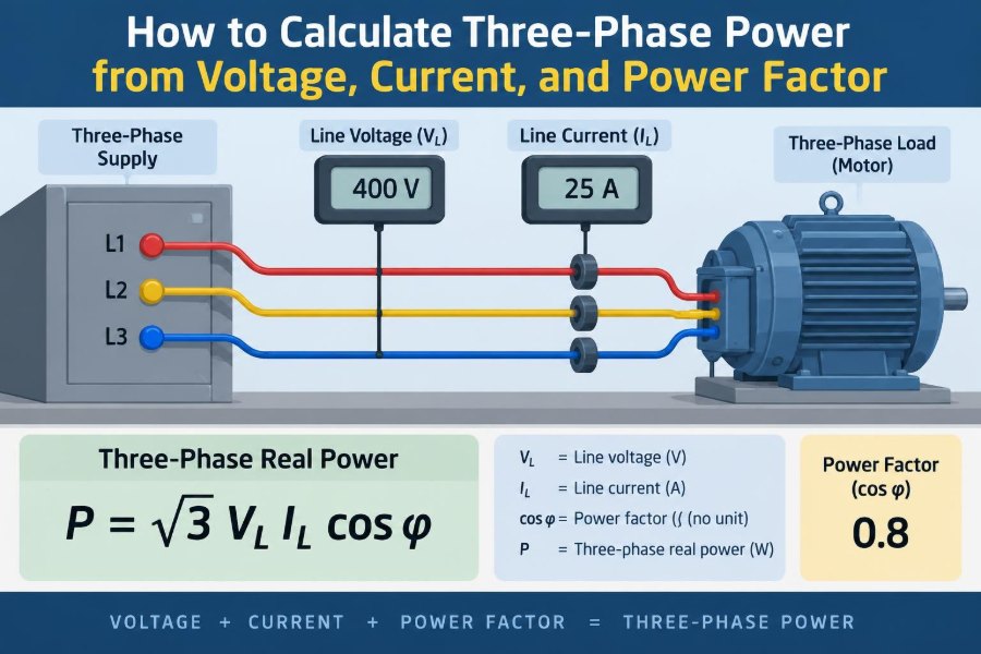

A motor nameplate says 400 V, 32 A, and 0.82 power factor. A technician needs to select a feeder, estimate energy use, or check whether a generator can carry the load. The arithmetic looks simple—until someone multiplies voltage by current and gets an answer that is far too low.
Three-phase power is everywhere in commercial buildings and industry: pumps, compressors, machine tools, HVAC equipment, welders, and distribution panels. Knowing how to calculate it turns readings from a meter into useful engineering information.
The key is to identify what the voltage means, what kind of power is being requested, and whether the load is balanced. Once those details are clear, the familiar square-root-of-three factor stops being a mystery and becomes a reliable tool.
This guide develops the formulas from the ground up, works through practical examples, and highlights the measurement traps that cause the most expensive mistakes.
🔌 What “Three-Phase Power” Means
A three-phase AC system uses three sinusoidal voltages with the same frequency and magnitude, displaced by 120 electrical degrees. This spacing lets the system deliver power more smoothly than a comparable single-phase supply.
In a balanced load, each phase carries an equal current and has the same impedance. Motors benefit especially from this arrangement because it produces a naturally rotating magnetic field.
For calculation purposes, total three-phase power is the sum of the power in all three phases. The common shortcut formulas work because the system is assumed to be balanced or close enough that the approximation is acceptable.
📏 Start by Identifying the Voltage
The voltage printed on switchgear, a motor nameplate, or a multimeter display is often the line-to-line voltage, also called line voltage. It is measured between any two phase conductors: L1–L2, L2–L3, or L3–L1.
In a wye-connected system, phase voltage is the voltage from a line conductor to neutral. These are not interchangeable values. For a balanced wye system:
Vline = √3 × VphaseThus, a 400 V line-to-line system has a phase-to-neutral voltage of about 231 V. Always record the meter connections along with the number; “400 V” alone does not fully describe a measurement.
⚙️ Understand Current: Line Current and Phase Current
Line current flows in each supply conductor. Phase current flows through one individual load phase or winding. Their relationship depends on whether the load is wye or delta connected.
For a balanced wye load, line current equals phase current. For a balanced delta load, line current is √3 times phase current. Fortunately, the standard total-power formulas using line voltage and line current apply to either balanced connection.
That convenience is why field calculations usually use clamp-meter current on a line conductor and voltage measured between two lines.
🧭 Distinguish Real, Reactive, and Apparent Power
AC power has three closely related quantities. Confusing them is one of the most common errors in electrical work.
| Quantity | Symbol | Unit | What it represents |
|---|---|---|---|
| Real power | P | watts (W) | Power converted to useful work, heat, light, or output |
| Reactive power | Q | volt-amperes reactive (var) | Energy exchanged with magnetic or electric fields |
| Apparent power | S | volt-amperes (VA) | Voltage-current loading seen by conductors and equipment |
A motor may draw substantial apparent power while delivering less real power because some current supports its magnetic field. Cables, transformers, and generators are commonly constrained by current and therefore by VA or kVA, not watts alone.
📐 The Core Formula for Real Three-Phase Power
For a balanced three-phase load, real power is:
P = √3 × VL × IL × PFWhere P is real power in watts, VL is line-to-line RMS voltage in volts, IL is line current in amperes, and PF is power factor. The factor √3 is approximately 1.732.
If voltage is in kilovolts and current is in amperes, the result is kilowatts. If voltage is in volts and current is in amperes, divide the watt result by 1,000 to obtain kW.
🧮 The Formula for Apparent Power
Apparent power does not include power factor:
S = √3 × VL × ILThe result is VA. Divide by 1,000 for kVA. This is the value often used to compare a load with transformer, UPS, switchgear, and generator ratings.
Apparent power is not “wasted” power. It is a measure of the combined voltage and current demand. A low power factor simply means that a smaller portion of that demand becomes real power.
🌀 The Formula for Reactive Power
For a sinusoidal, balanced load, reactive power is:
Q = √3 × VL × IL × sin(φ)Here, φ is the phase angle between voltage and current. Since power factor is cos(φ), calculate the angle only when needed: φ = cos⁻¹(PF).
Reactive power is usually expressed in kvar. Induction motors and transformers normally draw lagging reactive power; capacitor banks supply leading reactive power. In systems with significant waveform distortion, these simple sine-and-cosine relationships need more careful interpretation.
🔺 Why the √3 Factor Appears
It is tempting to calculate three-phase power as 3 × line voltage × line current. That is incorrect when both measured values are line quantities.
Each phase of a balanced wye load has power Vphase × Iphase × PF. Total power is three times that amount. Substituting Vphase = Vline/√3 and Iphase = Iline produces √3 × Vline × Iline × PF.
The same final expression emerges for a balanced delta load, even though the line and phase currents have a different relationship. The √3 factor accounts for the 120-degree geometry of the three phases.
🧾 Use RMS Values, Not Peak Values
Power formulas use RMS, or root-mean-square, voltage and current. RMS is the effective AC value that produces the same heating effect as an equivalent DC value.
A 400 V three-phase supply is normally specified as 400 V RMS line-to-line, not its peak value. Do not insert peak voltage into these formulas unless every other quantity has been converted consistently.
Most quality power analyzers and many digital multimeters display RMS values. Verify the instrument specification, particularly when measuring equipment that produces distorted current waveforms.
🛠️ Worked Example: A Balanced Motor Load
Consider a hypothetical motor drawing 28 A from a 400 V, three-phase supply at a measured power factor of 0.84. The real input power is:
P = 1.732 × 400 × 28 × 0.84
P = 16,300 W approximately
P = 16.3 kW approximately
Its apparent power is:
S = 1.732 × 400 × 28
S = 19.4 kVA approximately
The difference between 19.4 kVA and 16.3 kW reflects the load’s reactive component. These are electrical input quantities, not necessarily the mechanical output of the motor.
🏭 Example: Estimating Current from a Known kW Load
Sometimes the question is reversed: a process requires 45 kW, and you need an estimated running current on a 480 V supply. Rearrange the real-power formula:
I = P / (√3 × V × PF)Assuming a power factor of 0.90:
I = 45,000 / (1.732 × 480 × 0.90)
I = 60.1 A approximately
This is a planning estimate. Actual motor current depends on loading, efficiency, voltage, harmonic content, and the true power factor. Conductor sizing must also follow applicable code, installation conditions, and protection requirements—not just this calculated current.
🏷️ Nameplate Data Is Not Always Operating Data
A nameplate may list rated voltage, full-load current, rated output, efficiency, and power factor. Those figures describe the machine at specified rated conditions, not every operating point.
An induction motor running lightly loaded can have a noticeably lower power factor than at rated load. Its current may not fall in direct proportion to mechanical load because magnetizing current remains present.
For an operating energy calculation, measure actual voltage, current, and real power where possible. For equipment selection, use manufacturer data and the relevant engineering rules rather than assuming a nameplate value represents every condition.
🔗 Wye and Delta Connections in Practice
Wye and delta are ways of connecting the three load phases. A wye connection may provide a neutral point, while delta forms a closed loop without a neutral connection.
- Wye: phase voltage equals line voltage divided by √3; line current equals phase current.
- Delta: phase voltage equals line voltage; line current equals √3 times phase current.
When using measured line-to-line voltage and line current, apply the same total three-phase formulas to either balanced arrangement. The connection matters when calculating individual winding voltage or current, troubleshooting, or interpreting nameplate wiring diagrams.
⚖️ What “Balanced Load” Really Assumes
A balanced load has equal phase impedances, equal phase currents, and phase angles separated as expected. Large three-phase motors are often reasonably close to this condition when healthy and properly supplied.
Real installations can become unbalanced through uneven single-phase loads, loose terminations, failed capacitors, winding faults, or unequal source voltages. In those cases, one line current may be much higher than the others even if total kW seems acceptable.
The shortcut formula based on one current reading is only as good as the balance assumption. Measure all phases when diagnosing or commissioning equipment.
📊 Calculating an Unbalanced Three-Phase Load
For an unbalanced system, calculate or measure each phase power and add the results. In a four-wire wye system with sinusoidal conditions, a practical expression is:
Ptotal = PA + PB + PCEach phase’s real power can be found from its phase-to-neutral voltage, current, and individual power factor: Pphase = Vphase × Iphase × PFphase. A power analyzer is usually preferable because it measures phase angle directly.
Three-wire unbalanced systems are more complex because there is no neutral reference and phase relationships matter. The two-wattmeter method or a suitable three-phase power analyzer is a better field approach than forcing a balanced formula onto unequal currents.
📟 Choose the Right Measuring Instrument
A clamp meter tells you current, but current alone cannot reveal real power factor or real kW. A voltage reading plus an assumed power factor is useful for an estimate, not a complete measurement.
- Multimeter and clamp meter: useful for voltage and current checks.
- Power clamp meter: may calculate kW, kVA, power factor, and related values when connected correctly.
- Three-phase power analyzer: suited to detailed studies, imbalance, harmonics, and energy logging.
Match the instrument’s category rating, voltage rating, current range, and waveform capability to the installation. Measurement accuracy can deteriorate when a meter is used outside its stated conditions.
🧷 Connect Test Leads Safely and Correctly
Three-phase measurements expose workers to potentially hazardous energy. Follow site procedures, lockout and verification practices where work requires de-energization, and the instrument manufacturer’s connection sequence.
Voltage leads must be connected to the correct phases, and each current probe must surround only one conductor. Clamping around an entire multicore cable can cause magnetic fields to cancel, producing a meaningless current reading.
Current-probe direction also matters on many power analyzers. A reversed probe may display negative power or a misleading power factor. Confirm phase labels and probe arrows before trusting the result.
🧠 Power Factor Is More Than One Number
For clean sinusoidal waveforms, power factor corresponds closely to the cosine of the angle between voltage and current. This is often called displacement power factor.
Electronic drives, rectifiers, LED drivers, and other nonlinear loads can draw current in pulses. Their current distortion can reduce true power factor even when the fundamental voltage-current phase displacement is small.
Many basic formulas still give useful first-order results when a meter reports true power factor. But do not derive reactive power from sin(cos⁻¹(PF)) without checking whether harmonic distortion is significant; that relationship assumes sinusoidal conditions.
🌊 Harmonics Can Change the Measurement Story
Harmonics are voltage or current components at integer multiples of the fundamental frequency. Nonlinear loads can create harmonic current that heats conductors and transformers without producing proportional useful power.
A true-RMS meter measures effective current more accurately than an averaging meter when waveforms are distorted. Yet true RMS current alone still does not provide real power; the voltage waveform and timing relationship must also be considered.
Where variable-speed drives or large electronic loads are present, use an analyzer that can report real power, apparent power, power factor, and harmonic information. This helps distinguish a power-factor issue from a harmonic-current issue.
💡 From kW to Energy in kWh
Power is an instantaneous rate; energy accumulates over time. If a load consumes 16.3 kW steadily for six hours, its energy use is:
Energy = power × time
Energy = 16.3 kW × 6 h = 97.8 kWh
Actual loads often cycle, ramp, or idle. For those systems, use logged kW values or utility meter data rather than multiplying a nameplate rating by the shift length.
This distinction matters for cost estimates: utility energy charges generally relate to kWh, while capacity-related charges and equipment sizing may relate to peak kW, kVA, or demand rules.
🏗️ Why kVA Matters for Equipment Sizing
Transformers, generators, UPS systems, and many distribution components have thermal limits related to voltage and current. Their ratings are therefore commonly stated in kVA.
A 50 kW load at 0.80 power factor requires 62.5 kVA of apparent power before considering starting, transients, derating, future growth, and equipment-specific limits. At unity power factor, the same 50 kW would equal 50 kVA.
That does not mean multiplying every kW forecast by an arbitrary margin is sound design. Starting characteristics, load diversity, harmonics, ambient temperature, altitude, and manufacturer guidance all affect a defensible selection.
🔋 Motor Efficiency Is Separate from Power Factor
Power factor describes the relationship between real electrical input power and apparent electrical input power. Efficiency describes the relationship between useful output power and real input power.
Efficiency = output power / input real powerIf a motor delivers 15 kW of shaft power at 90% efficiency, it needs about 16.7 kW of real electrical input. If its power factor is 0.85, its apparent input is about 19.6 kVA.
Using output kW directly in the three-phase electrical formula without accounting for efficiency understates input current. Using power factor as though it were efficiency is a different but equally common mistake.
🚫 Mistake: Using Single-Phase Formulas
The single-phase real-power formula is P = V × I × PF. Applying it to a line-to-line voltage and one line current of a three-phase circuit misses the system geometry.
For example, 400 V × 28 A × 0.84 gives 9.4 kW, while the correct balanced three-phase result is about 16.3 kW. The missing multiplier is √3.
Use the single-phase formula only for one individual phase when you have that phase’s voltage and current, or for a genuinely single-phase circuit.
🚫 Mistake: Mixing Line-to-Line and Phase Voltage
Another error is to use phase-to-neutral voltage but still multiply by √3, or to multiply line-to-line voltage by three without converting it. Both approaches double-count or omit the voltage relationship.
Use one consistent pair:
- Line quantities:
P = √3 × Vline × Iline × PF - Phase quantities for a balanced load:
P = 3 × Vphase × Iphase × PF
Before calculating, write “L-L” or “L-N” beside the voltage value. That small habit prevents a large fraction of field calculation errors.
🚫 Mistake: Assuming Power Factor Is Always 1.0
Power factor equals 1.0 only when voltage and current are perfectly aligned and waveform effects are absent. Resistive heaters are often close to unity; motors and transformers generally are not.
Assuming unity power factor overestimates real kW from measured volts and amps. Conversely, assuming a generic power factor for a complex electronic load can be inaccurate in either direction.
If real power affects a billing, compliance, capacity, or troubleshooting decision, measure it with an appropriate instrument instead of relying on a convenient assumption.
🧪 A Practical Field Calculation Workflow
A repeatable workflow improves both speed and confidence:
- Confirm whether the circuit is three-phase and identify its nominal voltage system.
- Measure line-to-line RMS voltage and each line current safely.
- Check whether phase currents and voltages are reasonably balanced.
- Obtain true power factor from a power meter or use a clearly labeled estimate.
- Calculate kVA first, then calculate kW using measured power factor.
- Compare results with nameplate information and operating expectations.
If the readings disagree sharply, do not “correct” them by choosing a preferred formula. Investigate voltage connection, probe orientation, operating load, phase imbalance, instrument settings, and possible harmonic effects.
🔍 Use Results to Spot Abnormal Conditions
Power calculations are also diagnostic clues. A motor drawing unexpectedly high current and kVA may be overloaded, supplied at abnormal voltage, mechanically impaired, or affected by an electrical fault.
One phase with substantially different current can point to a connection issue, unequal loading, winding trouble, or a supply problem. A low power factor at unusually light motor load may be normal; a sudden change from a known baseline deserves investigation.
No single electrical reading proves a fault. Trend data, insulation and connection checks, mechanical observations, and manufacturer information provide the context needed for a sound diagnosis.
📋 Quick Formula Reference
For balanced, sinusoidal three-phase systems using RMS line-to-line voltage and line current:
Apparent power: S = √3 × VL × IL
Real power:     P = √3 × VL × IL × PF
Reactive power: Q = √3 × VL × IL × sin(φ)
Current:        IL = P / (√3 × VL × PF)
Use VA, W, and var when volts and amps are entered directly. Convert to kVA, kW, and kvar by dividing the result by 1,000. Keep units visible throughout the calculation.
✅ The Core Principle to Remember
Accurate three-phase power calculations begin with the correct electrical quantities: RMS line-to-line voltage, line current, and measured or justified power factor. For a balanced system, √3 ties those line measurements to the total power of all three phases.
Use kVA to understand current-related loading, kW to understand useful real input and energy consumption, and kvar to understand reactive demand. When the load is unbalanced or waveform distortion is significant, move from shortcut formulas to phase-by-phase measurement or a proper power analyzer.
The dependable rule is simple: for balanced three-phase circuits, calculate real power as √3 × line voltage × line current × power factor—and verify what every measured value actually represents. ⚡📐🔧