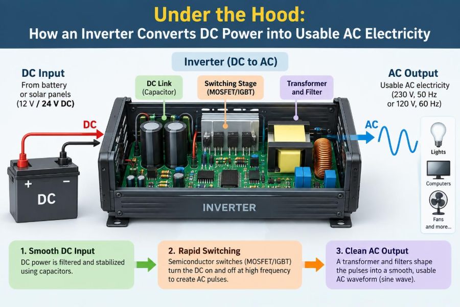

A laptop charger, a solar-power system, a camper van battery bank, and a household backup unit may look unrelated. Yet each depends on a device that solves the same electrical problem: many energy sources provide direct current, while much of the equipment people use expects alternating current.
That device is an inverter. It does not create energy from nothing; it reshapes electrical energy so that its voltage, frequency, and waveform suit the load.
The change sounds simple—DC in, AC out—but a modern inverter performs fast switching, careful timing, voltage control, filtering, sensing, and protection. Those details determine whether the output can safely run a phone charger, a refrigerator compressor, a motor drive, or sensitive laboratory equipment.
Understanding the process makes inverter ratings less mysterious and helps explain why waveform quality, battery size, wiring, and load type all matter.
🔌 The Basic DC-to-AC Problem
Direct current (DC) flows in one direction. A battery maintains a positive terminal and a negative terminal, so its voltage polarity remains fixed.
Alternating current (AC) repeatedly reverses direction. Utility power changes polarity in a smooth, repeating pattern, commonly at 50 Hz or 60 Hz depending on the region. An inverter must turn a fixed-polarity source into that reversing output.
⚡ Why So Many Systems Need Inverters
Batteries, solar photovoltaic modules, fuel cells, and many electronic power supplies naturally produce DC. Homes, grid-connected equipment, and many conventional appliances are designed around AC distribution.
Inverters bridge these worlds. They are found in uninterruptible power supplies, solar installations, electric vehicles, variable-speed motor drives, induction cooktops, portable power stations, and aircraft electrical systems.
🔋 DC Sources Have Real Limits
A battery is often described by voltage and capacity, but those labels do not mean it can deliver unlimited power. Internal resistance, temperature, state of charge, cable losses, and battery-management limits affect the available current.
At a given power level, lower DC voltage requires higher current. A 1,200 W load supplied from a 12 V battery system can require well over 100 A after allowing for inverter losses. That is why large systems often use 24 V, 48 V, or higher DC buses.
〰️ What “AC” Actually Means
AC is more than a voltage that occasionally changes sign. Its waveform has a frequency, an amplitude, and often a defined shape. Grid power is intended to be close to a sine wave because that form works well with transformers, motors, and many loads.
In a nominal 120 V RMS system, the instantaneous sine-wave voltage reaches a higher peak value. RMS, or root-mean-square, is the heating-equivalent value used to compare AC with DC for resistive loads. Confusing RMS and peak voltage leads to incorrect component ratings.
🧱 The Inverter’s Main Building Blocks
Although designs vary, most power inverters contain a small set of functional stages. Thinking in stages is more useful than treating the enclosure as a black box.
- A DC input stage receives power from the battery, solar DC bus, or another source.
- A switching bridge rapidly connects the DC supply in controlled directions.
- A controller creates switching commands and monitors operating conditions.
- Magnetic components and capacitors adjust and smooth the output.
- Protection circuits disconnect or limit operation during faults.
🧠 The Controller Sets the Timing
The controller is the inverter’s decision-maker. It measures quantities such as output voltage, current, DC-bus voltage, temperature, and sometimes grid phase. It then adjusts switch timing to maintain the intended output.
Older and simpler units may use dedicated control integrated circuits. More capable products use microcontrollers or digital signal processors, especially where synchronization, communications, battery coordination, or motor control is required.
🔀 Power Switches Do the Fast Work
Inverters use semiconductor switches, commonly MOSFETs at lower voltages and IGBTs in many higher-voltage applications. These devices are operated mostly in either an on state with low voltage drop or an off state with very little current.
This switching approach is far more efficient than trying to dissipate excess power continuously in a linear control device. However, each transition has loss, and the switches must be driven correctly to avoid damage.
🌉 The H-Bridge Reverses Polarity
A common single-phase arrangement is an H-bridge: four switches arranged so the load can be connected to the DC source in either direction. One controlled pair applies positive polarity; another pair applies negative polarity.
If the switches alternated only a few times per second, the result would resemble a crude square wave. Useful inverters switch far more rapidly and use that speed to shape the average output.
⏱️ Dead Time Prevents a Dangerous Short Circuit
In one leg of a bridge, the upper and lower switch must never be fully on at the same time. If they are, the DC source is shorted directly through the switches, an event called shoot-through.
Controllers insert a brief intentional delay, called dead time, between turning one switch off and the opposing switch on. Too little dead time risks failure; too much distorts the waveform and can reduce performance. This is a practical example of why gate-drive design matters.
📐 Pulse-Width Modulation Shapes the Output
Most sine-wave inverters use pulse-width modulation, or PWM. Rather than outputting a continuously smooth voltage directly, the bridge produces many high-frequency pulses whose widths vary throughout each AC cycle.
Near the sine wave’s zero crossing, the pulses deliver less average voltage. Near its positive or negative peak, they deliver more. Over a short interval, the average follows a sine-shaped reference.
🎼 A Simple Analogy for PWM
Imagine dimming an LED by switching it on and off very quickly. The LED is either fully on or off, but the eye perceives a lower brightness when it is on for less of each cycle.
PWM uses the same averaging principle with electrical voltage. The load and output filter respond mainly to the desired low-frequency waveform while reducing the high-frequency switching content.
🌊 From Pulses to a Sine Wave
A PWM bridge alone produces a pulsed waveform, not a perfectly smooth sine wave. An output filter, often using inductors and capacitors, attenuates much of the switching-frequency energy.
Inductors resist rapid changes in current, while capacitors help absorb rapid voltage variation. Their values must be chosen for the intended switching frequency, load range, voltage, and allowable distortion. A poorly designed filter can cause overheating, poor regulation, or unwanted resonance.
📊 Square Wave, Modified Wave, and Pure Sine Wave
Not all products marketed as inverters provide the same output quality. The terminology affects compatibility as well as cost.
| Output type | General form | Typical implication |
|---|---|---|
| Square wave | Rapid jumps between positive and negative levels | Simple but high harmonic content; often unsuitable for many modern loads |
| Modified sine wave | Stepped approximation to AC | Can operate some equipment but may create noise, heat, or compatibility problems |
| Pure sine wave | Filtered waveform close to a sine wave | Usually the most broadly compatible option |
A “pure sine wave” label does not mean mathematically perfect output. It generally means the waveform distortion is controlled well enough for intended equipment. Manufacturer specifications and the actual load still matter.
🧩 Harmonics Explain Why Waveform Quality Matters
A harmonic is a frequency component at an integer multiple of the fundamental frequency. A square wave contains substantial odd harmonics, while a well-filtered sine-wave inverter keeps unwanted components much lower.
Resistive heaters may work acceptably on a rough waveform, but motors, transformers, audio equipment, some chargers, and timing-sensitive electronics can behave differently. Extra harmonics can cause audible buzz, added heating, vibration, or unreliable operation.
🔺 Voltage Conversion Happens Too
Many inverters must do more than reverse polarity. A 12 V battery cannot directly supply a 120 V or 230 V AC output at the required level, so the inverter includes a voltage-conversion stage.
Some designs first use a high-frequency DC-DC converter to raise the battery voltage to a higher DC bus. The switching bridge then creates AC from that bus. Other designs use a transformer associated with the output stage. The best architecture depends on power, isolation requirements, cost, size, and performance goals.
🧲 Why High-Frequency Transformers Are Smaller
Transformers transfer energy through changing magnetic flux. At higher operating frequencies, a transformer can generally use less magnetic core material for a given power transfer than a low-frequency transformer.
This is one reason modern switch-mode inverters can be compact. It does not eliminate the need for careful insulation, cooling, electromagnetic compatibility, and protection; it simply changes the engineering tradeoffs.
🎚️ Regulation Keeps Output Near Its Target
Loads do not stay constant. A refrigerator may draw a modest running power but demand a much larger current while its compressor starts. A power tool may change demand as the cutting load changes.
Feedback control compares measured output with the desired voltage and adjusts PWM duty cycle or other control variables. Regulation has limits: if the DC source sags severely or the load exceeds the inverter rating, output voltage may drop or the inverter may shut down.
🚀 Surge Power Is Different from Continuous Power
Continuous power is what an inverter can provide over an extended operating period under stated conditions. Surge power is a higher output it may support briefly for starting motors or charging input capacitors.
A 1,000 W continuous inverter is not automatically suitable for every appliance labeled below 1,000 W. The appliance’s starting behavior, power factor, waveform tolerance, and the battery system’s current capability all affect the outcome.
🔄 Power Factor Changes the Current Story
For a purely resistive load, voltage and current rise and fall together. Motors, transformers, and many electronic supplies can shift or distort current relative to voltage. This behavior is described partly by power factor.
Low power factor can mean more current for the same useful real power, increasing stress on switches, wiring, and the source. Inverters must be designed for both real power and current-related limits, not only a single watt number.
🔥 Efficiency Is Not a Single Number
Every stage loses some energy through semiconductor conduction, switching transitions, magnetic losses, capacitor resistance, control electronics, and cooling fans. That energy becomes heat.
Efficiency normally changes with load. An inverter can be efficient near a designed operating range but consume a noticeable amount while idling or lightly loaded. For an off-grid system that operates all day, idle draw can be as relevant as peak efficiency.
❄️ Thermal Design Determines Real Capability
Power devices have temperature limits. Heat sinks, fans, metal enclosures, thermal interfaces, airflow paths, and temperature sensors keep internal components within safe operating conditions.
A unit may reduce output, alarm, or shut down when it becomes too hot. Installing it in a sealed compartment, covering vents, or placing it next to a heat source can reduce its usable power even when its nameplate rating appears adequate.
🛡️ Protection Circuits Handle Predictable Faults
Well-designed inverters monitor for conditions that could damage the inverter, battery, wiring, or connected equipment. Protection does not make unsafe installation harmless, but it provides an essential last line of defense.
- Low-voltage cutoff helps prevent excessive battery discharge.
- Overvoltage protection addresses abnormal input voltage.
- Overcurrent and short-circuit protection limit fault energy.
- Overtemperature protection responds to overheating.
- Output fault detection responds to abnormal AC conditions.
Protection thresholds and behavior vary. Some units retry automatically; others require manual reset.
🔌 Input Cables Are Part of the Power Circuit
High-current DC wiring deserves special attention. Cable resistance causes voltage drop and heating, and a loose connection can become a serious hot spot. A short battery cable with suitable conductor size is usually preferable to a long, undersized run.
Fusing or circuit protection should be placed according to the system design, commonly close to the energy source so a damaged cable is protected. Exact conductor and overcurrent-device selection should follow applicable electrical requirements and the equipment manufacturer’s instructions.
🌍 Grounding and Neutral Are Not Universal Details
AC grounding arrangements differ among portable, vehicle, residential, and grid-connected systems. Some inverter outputs have a bonded neutral and ground; others use a floating output or make bonding conditional on operating mode.
Assuming every outlet behaves exactly like a utility receptacle can be unsafe. Grounding, transfer switching, residual-current protection, and neutral bonding should be planned as a system, particularly when an inverter connects to building wiring. Qualified electrical advice is appropriate for permanent installations.
🏠 Stand-Alone, Grid-Tied, and Hybrid Inverters
A stand-alone inverter supplies local loads from a DC source without exporting power to a utility grid. It must establish its own AC voltage and frequency.
A grid-tied inverter measures the existing grid waveform and injects current in synchronism with it. A hybrid inverter can coordinate batteries, solar generation, loads, and grid interaction. Grid-connected equipment must meet local interconnection and anti-islanding requirements; it is not interchangeable with a portable inverter.
🔗 Synchronization Is Essential for Grid Connection
Before a grid-tied inverter exports energy, it must match the grid’s voltage, frequency, and phase closely enough to connect safely. Its control system then regulates current flow rather than simply forcing its own independent voltage waveform.
If utility power disappears, approved grid-interactive equipment must stop energizing the external grid. This anti-islanding behavior protects utility workers and avoids an uncontrolled local island on utility conductors.
☀️ Solar Inverters Also Track Maximum Power
A solar module’s best operating voltage changes with sunlight and temperature. Many solar inverters include maximum power point tracking, or MPPT, to seek the operating point where the array can provide the most available power at that moment.
MPPT is a DC-side control function, while inversion creates usable AC. They often appear in the same product, but they solve different problems.
🌀 Motor Drives Use Inversion in a Different Way
Variable-frequency drives rectify incoming AC to DC, then invert it back to controlled AC for a motor. By changing output frequency and voltage, the drive can vary motor speed and torque.
Three-phase motor drives coordinate three output waveforms separated in phase. The principle remains familiar: semiconductor switching and PWM create a controlled AC waveform from a DC link.
📱 Sensitive Electronics and “Dirty” Loads
Modern chargers often rectify AC internally, so many will operate from a broad range of inputs. That does not guarantee that every charger, medical device, audio system, appliance, or motor will tolerate every inverter waveform.
Loads can also affect the inverter. Welders, compressors, pumps, and some tools may create high inrush current or electrical noise. When compatibility is uncertain, use manufacturer guidance and test cautiously rather than relying only on a wattage label.
⚠️ Common Sizing Mistakes
The most frequent mistake is selecting an inverter based only on the running watts printed on one appliance. A workable design begins with the load profile, not the largest convenient product listing.
- Ignoring motor startup current or compressor surge.
- Forgetting inverter idle consumption.
- Using a battery that cannot safely supply the required DC current.
- Choosing long or undersized DC leads.
- Assuming a stepped waveform suits all equipment.
- Connecting a portable inverter to building wiring without approved transfer equipment.
🧮 A Practical Planning Example
Consider a hypothetical 800 W appliance powered from a 12 V battery through an inverter. If the inverter is not perfectly efficient, its DC input power must be greater than 800 W. The battery current can therefore approach or exceed roughly 75 A depending on operating conditions.
This estimate is not a wiring prescription; it illustrates the central point. Low-voltage, high-power systems move substantial current, so battery limits, terminals, fuse ratings, conductor sizing, and voltage drop must be evaluated together.
🔍 What to Read on an Inverter Datasheet
Useful specifications include continuous output rating, surge rating and duration, output voltage and frequency, waveform description, efficiency at relevant load conditions, no-load consumption, input-voltage range, and operating temperature limits.
Also look for details that match the intended job: transfer time for backup power, charging capability for hybrid units, output neutral arrangement, approved use environment, communications options, and compliance markings relevant to the installation location.
🧰 Installation Practices That Improve Reliability
Mount the inverter where air can circulate and where it is protected from moisture, conductive debris, and accidental mechanical damage. Keep DC connections clean, tight, and accessible for inspection.
Separate sensitive signal wiring from high-current switching paths when practical. Follow torque instructions for terminals, use properly rated connectors and overcurrent protection, and disconnect energy sources before servicing. Capacitors can retain hazardous energy after shutdown, so service procedures matter.
🧭 Troubleshooting Starts with the Source
When an inverter alarms or shuts down under load, the apparent problem may be upstream. Measure DC voltage at the inverter input while the load is operating, not only with no load connected. A large drop can point to a weak battery, inadequate cabling, a poor connection, or insufficient source capacity.
Then check load behavior, ventilation, fault indicators, and configuration settings. Repeatedly resetting an inverter without identifying the cause can stress both the unit and the electrical system.
🧪 What an Oscilloscope Reveals
An oscilloscope can show the difference between a stepped waveform, PWM switching activity, and a filtered sine-like output. It can also reveal distortion under changing loads, though measuring inverter output safely requires correctly rated probes and careful technique.
Voltage alone is not the whole story. Current waveforms, switching noise, harmonic content, thermal behavior, and response to transients all contribute to inverter performance.
🚧 Safety Boundaries Matter
Inverter outputs can cause electric shock, start fires through faulty wiring, and backfeed circuits if installed incorrectly. Battery systems can deliver very high fault current even at comparatively low voltage, and lithium-based systems add specific battery-management and installation considerations.
Do not improvise connections to household circuits. Permanent, grid-connected, or high-power installations should be designed and inspected in accordance with applicable local rules by competent people. This article explains principles, not a substitute for a site-specific electrical design.
🧩 The Core Principle: Controlled Switching Creates Useful AC
An inverter works because fast semiconductor switches can be controlled precisely. A bridge alternates the applied polarity, PWM controls the average voltage over time, and filtering plus feedback refine that switching into an output suitable for a particular load.
The result depends on the entire system: a capable DC source, correctly sized conductors, sensible thermal design, waveform quality appropriate to the equipment, and protection that responds when conditions move outside safe limits.
An inverter is best understood not as a magic DC-to-AC box, but as a carefully controlled power-conversion system that trades fast switching for stable, usable electricity. ⚡🔋🔧