
A metal-cased washing machine works perfectly for years, until insulation inside a cable deteriorates and a live conductor touches the cabinet. Without a safe fault path, the cabinet can remain energized while appearing completely normal.
Or consider a lightning strike near a building, a generator changeover at a factory, or a sensitive control system that starts producing erratic readings. These events look unrelated, but each involves the way electrical energy is referenced, contained, and safely directed.
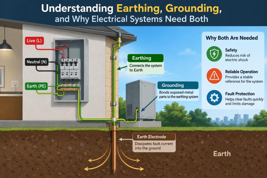
That is where earthing and grounding enter the picture. The terms are often used interchangeably, and in some regions they genuinely overlap. Yet in electrical design, they can describe different connections with different jobs.
Understanding those jobs helps students read diagrams more confidently, helps technicians troubleshoot safely, and helps everyone appreciate why a green-and-yellow conductor is never “just another wire.”
⚡ The Central Idea: Give Fault Energy a Safer Path
Electrical systems need a deliberate way to deal with abnormal current, static charge, lightning energy, and unwanted voltage on exposed metal. A well-designed earthing and grounding arrangement creates controlled reference points and low-impedance paths for those conditions.
The objective is not to make every electrical problem disappear. It is to ensure that faults produce predictable behavior: protective devices operate, dangerous touch voltages are limited, and equipment has a stable electrical reference.
🌍 Earthing and Grounding: Why the Words Vary
Usage depends on country, standard, industry, and context. In much UK- and IEC-influenced language, earthing commonly means connecting exposed conductive parts to Earth for protection. In North American practice, grounding may cover both equipment bonding and connecting a system conductor to ground.
For clear communication, engineers should state what is actually connected: an equipment enclosure, a circuit neutral, a lightning protection down conductor, or an electrode in soil. The physical connection matters more than the label.
🧭 A Useful Distinction: Equipment Earth and System Ground
An equipment earthing conductor connects accessible metal parts, such as motor frames, panel enclosures, and appliance cases, to the protective earthing system. Its purpose is primarily shock protection during a fault.
A system grounding connection connects one point of the power system—often a transformer neutral or generator neutral—to ground. It establishes a reference and influences how earth faults behave. One installation may require both, but they do not perform the same function.
🔩 Bonding Comes Before Many Grounding Questions
Bonding means intentionally connecting conductive parts together so they remain at nearly the same electrical potential. Typical bonded items include equipment enclosures, cable trays, structural steel, metal piping, and protective conductors where permitted and required.
If a person touches two bonded metal parts, there should be little voltage difference between them. This is often more immediately relevant to shock protection than the resistance of a distant ground rod.
🧠 Voltage Is Always Between Two Points
People sometimes say that a conductor “has voltage,” but voltage is a difference between points. A 230 V line conductor is 230 V relative to its reference conductor; a metal enclosure becomes hazardous when its voltage differs significantly from the surface a person is standing on or another object they can touch.
Earthing and bonding manage these differences. They aim to keep accessible conductive parts near the local earth potential and, crucially, to make fault conditions clear enough for protective equipment to respond.
🛡️ The Basic Fault Scenario
Imagine a phase conductor inside a drill becomes loose and touches the metal housing. If the housing is properly connected to the protective conductor, a low-impedance fault loop is created back toward the source.
The resulting fault current should cause a fuse, circuit breaker, or other protective device to disconnect the supply quickly. Without that protective path, the housing may stay live until a person provides an accidental route to earth.
🔁 The Fault Loop Must Return to the Source
A frequent misconception is that fault current simply “goes into the ground.” In most low-voltage systems, effective operation of an overcurrent protective device depends on a complete loop back to the transformer or generator source.
Soil is usually a poor and variable conductor compared with copper or aluminum conductors. A ground electrode can be essential for system grounding and lightning protection, but it is not generally a substitute for a continuous equipment protective conductor.
⏱️ Why Low Impedance Matters More Than Low Resistance Alone
At power frequency, resistance is an important part of a fault path. But conductors, connections, and geometry also have inductive effects, particularly during fast transients such as lightning or switching events. The broader term impedance captures both resistance and reactance.
Short, direct, well-bonded conductors generally perform better than long, looping paths. A connection that seems acceptable on a basic resistance test may behave poorly during a fast surge because its inductance limits current rise.
🌐 What an Earth Electrode Actually Does
An earth electrode is a conductor intentionally placed in contact with soil: a rod, plate, ring, foundation electrode, or grid. It connects the installation’s earthing system to the surrounding earth mass.
Its duties may include stabilizing a system reference, dissipating lightning current, managing static charge, and supporting particular fault-protection arrangements. Its required performance depends on the installation design, local rules, soil conditions, and fault-clearing method.
🪨 Soil Is Not a Uniform Conductor
Earth resistance varies with moisture, temperature, soil chemistry, compaction, and electrode depth. Dry, rocky, frozen, or sandy ground can provide much poorer electrical contact than moist soil.
That variability is why a single rod cannot be assumed to solve every grounding problem. Large facilities may use multiple electrodes, a buried ring, or a ground grid designed for site conditions and verified by appropriate testing.
🏠 Protective Earthing in Homes and Small Buildings
In a typical building, protective conductors connect socket outlets and fixed equipment to an earthing terminal or bar. Exposed metal parts are bonded so an insulation fault is likely to produce a sufficiently large and predictable fault current.
The exact arrangement varies by supply system. Some systems provide an earth path from the utility; others rely more heavily on local electrodes. A qualified designer must follow the applicable installation rules rather than copying a diagram from another region.
🏭 Industrial Sites Need an Earthing Network
Factories contain motors, variable-speed drives, transformers, switchboards, cable tray systems, control cabinets, and extensive structural metalwork. Each creates potential fault, electromagnetic compatibility, or surge concerns.
Instead of treating each machine as an isolated grounding task, industrial design usually develops an integrated bonding and earthing network. This reduces uncontrolled potential differences and provides defined paths for fault and surge currents.
⚙️ Grounding a Transformer Neutral
Many AC systems intentionally ground the transformer neutral point. This establishes phase-to-earth voltages and gives earth faults a known return path. The grounding method strongly affects fault current and protection coordination.
A solidly grounded system permits relatively high earth-fault current, which can help conventional protective devices clear faults quickly. Other systems use impedance grounding or may operate with an isolated neutral under controlled conditions to limit fault damage or maintain continuity temporarily.
📐 Common Neutral-Ground Arrangements
| Arrangement | General purpose | Design consideration |
|---|---|---|
| Solid grounding | Provides a direct neutral reference and substantial earth-fault current. | Protection must interrupt fault energy safely and selectively. |
| Resistance grounding | Limits earth-fault current through a resistor. | Often requires dedicated fault detection and maintenance procedures. |
| Reactance grounding | Uses inductive impedance to control fault current. | Requires careful system studies and coordination. |
| Isolated or ungrounded operation | May continue through a first earth fault in specific systems. | Insulation monitoring and prompt fault location are essential. |
No arrangement is universally best. The choice depends on voltage level, process continuity needs, arc-flash considerations, equipment ratings, and the governing electrical standard.
🚫 Neutral and Protective Earth Are Not Interchangeable
Neutral is normally a current-carrying circuit conductor. Protective earth is intended to carry current only under fault conditions, leakage conditions, or certain transient events. Joining them casually downstream of the designated bonding point can place normal return current on exposed metal and parallel paths.
This can cause nuisance tripping, corrosion in metalwork, interference with communications, and shock hazards. The permitted neutral-to-earth connection location is a design rule, not a field improvisation.
🧯 Residual-Current Devices Add Another Layer
Residual-current devices, often called RCDs, GFCIs, or RCCBs depending on type and region, compare current leaving on live conductors with current returning. A difference suggests leakage somewhere else, possibly through earth or a person.
They can provide valuable additional protection, especially where fault-loop impedance is high or people use portable equipment. They do not eliminate the need for correct earthing, bonding, conductor sizing, and overcurrent protection.
⚡ Lightning Requires a Different Timescale
Lightning currents rise and change extremely quickly. A lightning protection system therefore emphasizes short, straight down conductors, robust joints, bonding of nearby metal systems, and an earth termination system designed to spread energy.
Sharp bends and long loops add inductance, encouraging voltage differences and side-flashing between conductive paths. A lightning earth arrangement must be coordinated with the wider electrical installation, not installed as an isolated rod with no bonding strategy.
📡 Signal Grounding and Electrical Noise
Electronic systems often need a stable signal reference, but signal ground is not automatically the same as a protective earth conductor. Analog sensors, high-frequency circuits, communication cables, and power electronics can experience noise when return paths are poorly planned.
Good practice may involve shielding, segregating noisy power cables from sensitive signals, controlled single-point connections at low frequency, or carefully designed multipoint bonding at high frequency. The right approach depends on frequency and equipment design.
🔄 Ground Loops Are Not Always the Same Problem
In instrumentation, a “ground loop” often means multiple return paths that allow unwanted circulating current and introduce measurement noise. In power safety discussions, multiple bonded paths may be intentional and desirable for fault current and equipotential bonding.
The lesson is to identify the current involved. A path helpful for clearing a fault may be troublesome for a millivolt-level sensor signal. Separate safety grounding questions from signal-integrity questions before choosing a remedy.
🌊 Step and Touch Voltage
When significant current enters soil, voltage is not distributed evenly around the electrode. Two points on the ground surface can have different potentials. Step voltage is the potential difference between a person’s feet; touch voltage is the difference between a hand-contacted object and the ground at the person’s feet.
These effects matter especially around substations, utility structures, and lightning protection systems. Ground grids, crushed-rock surfaces, bonding, and site-specific engineering can reduce exposure, but design requires careful assessment.
🧱 Equipotential Bonding Protects the Person
“Equipotential” means keeping nearby conductive objects at closely similar voltage during a fault or surge. In a bathroom, for example, metal pipes, structural metal, and electrical protective conductors may require bonding under applicable rules because a person could contact more than one item.
The goal is not simply to connect metal to dirt. It is to prevent a dangerous voltage from appearing across a person’s body when simultaneous contact occurs.
🔍 Testing Is More Than Measuring a Ground Rod
Testing may include continuity checks of protective conductors, verification of bonding connections, earth electrode resistance measurements, fault-loop impedance testing, insulation testing, and functional tests of residual-current devices. Each test answers a different question.
A low electrode resistance alone does not prove that a breaker will clear an equipment fault. Likewise, a good continuity reading does not prove that surge protection or lightning bonding is properly designed.
🧰 Inspection Points That Often Reveal Problems
- Loose, corroded, painted-over, or mechanically damaged bonding connections.
- Protective conductors disconnected during equipment replacement or renovation.
- Improvised neutral-to-earth links inside downstream panels or equipment.
- Ground rods used as the only protective path for metal-cased equipment.
- Shield drains connected inconsistently, creating noise or unintended return paths.
- Undocumented changes to generators, transformers, or transfer switches.
Inspection should be performed with safe isolation procedures and suitable instruments. A visual check can find defects, but it cannot establish every electrical property.
🔌 Portable Generators Create Special Questions
A generator may have a floating neutral, a bonded neutral, or a switching arrangement that changes its relationship to the building supply. The correct configuration depends on whether it feeds standalone loads, a transfer switch, or a separately derived system.
Incorrect neutral bonding can defeat residual-current protection, create parallel neutral current, or leave fault protection ineffective. Generator installation is a case where the manufacturer’s instructions and local electrical rules must be read together.
☀️ Solar, Batteries, and Inverters Need Coordinated Earthing
PV arrays, battery systems, inverters, and DC distribution equipment introduce additional conductive frames, DC circuits, surge exposure, and fault-detection requirements. Equipment frames generally need protective bonding, while DC conductor grounding depends on the inverter and system topology.
Do not assume a familiar AC grounding rule applies unchanged on the DC side. Some systems use isolated DC circuits with insulation monitoring; others have intentionally grounded conductors. Follow the listed equipment design and applicable installation requirements.
🧪 Static Electricity Has a Different Energy Profile
Static charge can be harmlessly annoying on a dry day, yet hazardous where flammable vapors, dusts, or sensitive electronics are present. Bonding conductive containers together before transfer helps prevent a spark caused by a potential difference.
Grounding provides a path for charge dissipation, while bonding ensures two objects being connected or separated do not sit at different potentials. Both may be required in fuel handling, chemical processing, and electronics manufacturing.
⚠️ Common Misconceptions to Leave Behind
- “Earth absorbs all fault current.” Effective fault clearing usually requires a complete return path to the source.
- “Any metal pipe is a reliable earth.” Pipe materials, joints, alterations, and service conditions can make this unsafe or noncompliant.
- “A ground rod makes an appliance safe.” A properly sized, continuous protective conductor and fault-clearing path are still necessary.
- “More connections are always better.” Extra connections can create parallel currents, noise, and unintended neutral paths.
- “No shock means no problem.” A defective earth may remain unnoticed until a fault occurs.
📋 Design Starts With the Supply Arrangement
Before selecting conductors or electrodes, identify the source, voltage, neutral configuration, available fault current, protective devices, and method of disconnection. The supply arrangement determines what fault loop is expected and how quickly protection must operate.
Then consider the environment: wet locations, corrosive atmospheres, explosive hazards, outdoor exposure, medical spaces, data systems, and large public areas all introduce additional requirements and consequences.
📏 Conductor Sizing Is a Thermal and Mechanical Decision
Protective and grounding conductors must withstand expected fault current for the clearing time without unacceptable damage. Their sizing also considers mechanical robustness, corrosion, installation method, and rules governing minimum conductor sizes.
A conductor that is adequate for normal leakage or static dissipation may be inadequate for a high-energy fault. Conversely, simply choosing a very large conductor does not fix a poor fault-loop arrangement or an incorrectly coordinated protective device.
🧑🔧 When to Stop and Call a Qualified Professional
Work involving service panels, transformer neutrals, generators, electrodes, lightning systems, and protective conductor alterations can create serious hazards even when the supply appears off. Stored energy, alternate feeds, and incorrect assumptions about neutral conductors are common risks.
Students can learn the principles through diagrams, supervised laboratory work, and safe low-voltage demonstrations. Real installation changes should be designed, inspected, and tested by competent people working under the applicable rules.
🗺️ Standards Set the Details, Principles Set the Direction
Electrical codes and standards differ in terminology, permitted earthing arrangements, test methods, and installation details. Those documents are essential for real work, but they rest on recurring physical principles: create reliable fault paths, limit accessible voltage differences, control fault energy, and verify the result.
When reading a standard, ask what hazard each requirement controls. That habit turns a memorized rule into an engineering decision that can be applied thoughtfully in unfamiliar systems.
✅ The Core Principle to Remember
Earthing connects an installation to the mass of Earth; grounding may describe that connection, system reference connections, or both depending on local practice. Bonding connects conductive parts together so dangerous voltage differences are less likely to develop.
The most effective protection comes from treating the whole arrangement as a system: source grounding, protective conductors, bonding, fault-loop impedance, disconnecting devices, electrodes, surge measures, and testing must work together.
A ground rod, a green conductor, or a breaker alone is not a complete answer. Safety depends on whether a fault has a defined path and whether the system responds in the intended time.
Electrical systems need earthing and grounding not as symbolic connections to the soil, but as coordinated engineering measures that control voltage, direct fault current, and protect people and equipment. ⚡🌍🛡️