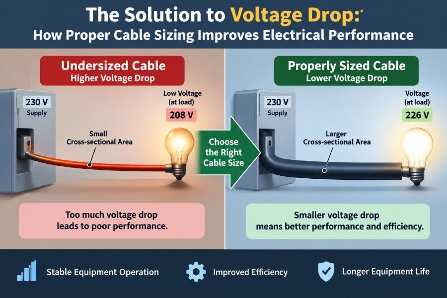

A pump starts normally when the building is quiet, then struggles when other loads come online. A long run of landscape lighting looks bright near the transformer but noticeably dim at the far end. A workshop receptacle reads close to its expected voltage with no load, yet a compressor causes the lights to flicker when it starts.
These are familiar electrical problems, and they are often blamed on the equipment first. Sometimes the equipment is at fault. But a conductor that is too small for its length, current, installation conditions, or load can be the quieter cause.
Voltage drop is not merely a number on a design worksheet. It changes motor torque, heating performance, lighting quality, electronic reliability, and the useful capacity of an electrical system. It also turns energy into unwanted heat along the cable route.
Proper cable sizing does not mean selecting the largest conductor available. It means choosing a conductor with adequate ampacity, acceptable voltage drop, suitable insulation, and a construction appropriate for the actual installation. That distinction is where sound electrical design begins.
⚡ What Voltage Drop Actually Means
Voltage drop is the reduction in electrical potential between the source and the load caused by impedance in the circuit conductors. In a simple resistive circuit, the relationship is described by Ohm’s law: Vdrop = I × R.
Every real conductor has resistance. When current flows, some source voltage is used to push that current through the cable itself, leaving less voltage available at the connected equipment.
🔌 A Simple Water-Flow Analogy
A cable can be compared with a water pipe. A narrow, long pipe restricts flow more than a wide, short pipe; similarly, a small, long conductor has more resistance than a larger, shorter one.
The analogy has limits, because AC circuits also involve reactance and power factor. Still, it captures the central design question: can the path deliver what the load needs without losing an excessive portion along the way?
📏 Why Cable Length Changes Everything
Resistance increases with conductor length. A load located twice as far from its supply generally has twice as much conductor resistance in the path, assuming the same conductor size and material.
Designers must consider the full circuit path. For a typical single-phase two-wire circuit, current travels out on one conductor and returns on the other. The effective loop length is therefore greater than the one-way distance to the load.
🔢 The Relationship Between Current and Drop
For a given cable, voltage drop rises as current rises. A lightly loaded circuit may appear perfectly acceptable, then reveal a serious problem when a heater, motor, charger, or group of loads draws its expected current.
This is why measurements taken with no load can mislead troubleshooting. The useful test is voltage at the load terminals while the equipment is operating, especially during demanding conditions such as motor starting.
🧵 Conductor Size Controls Resistance
A larger conductor cross-sectional area has lower resistance per unit length. In American Wire Gauge notation, a smaller gauge number represents a physically larger conductor; this naming convention can confuse newcomers.
Increasing conductor size reduces voltage drop, but it also raises cost, cable weight, bending difficulty, termination requirements, and conduit fill. Good design balances these practical constraints rather than treating upsizing as automatic.
🧱 Copper and Aluminum Are Not Interchangeable
Copper and aluminum are both widely used conductor materials, but aluminum has higher resistance for an equivalent cross-sectional area. An aluminum conductor generally needs a larger area than a copper conductor to provide similar resistance and ampacity performance.
Material selection also affects lugs, connectors, oxide control, torque procedures, and installation practice. Use conductors and terminations listed for the material involved; never assume a size substitution alone makes two installations equivalent.
🌡️ Temperature Raises Conductor Resistance
As a metallic conductor warms, its resistance increases. A cable operating in a hot ambient area, packed with other circuits, or carrying sustained high current can experience more voltage drop than a room-temperature calculation suggests.
Temperature also matters because conductor insulation has a maximum operating rating. A voltage-drop calculation cannot replace ampacity evaluation, correction factors, and the temperature limits of the complete termination system.
〰️ AC Circuits Add Impedance
In AC systems, voltage drop is influenced by impedance, which includes resistance and reactance. Reactance is associated with changing magnetic and electric fields and can become especially relevant with long runs, large conductors, grouped phase conductors, and certain wiring methods.
For many short, low-voltage branch circuits, resistance dominates the practical calculation. For larger feeders, long distribution runs, and three-phase systems, use an impedance-based method appropriate to the installation rather than relying on a simplified DC assumption.
📐 Power Factor Affects AC Calculations
Power factor describes how current relates in phase to voltage in an AC load. Motors, transformers, and other inductive loads may have a power factor below unity, meaning both resistance and reactance contribute differently to the calculated voltage drop.
This does not make basic estimates useless. It means estimates should be treated as screening tools, while critical installations deserve calculations using recognized design data and the expected operating characteristics of the load.
🔄 Single-Phase and Three-Phase Paths Differ
Single-phase circuits commonly use a two-conductor loop, so the out-and-back path is central to voltage-drop calculations. In balanced three-phase systems, the current paths and phasor relationships differ, and a common form includes a factor of √3.
Do not transfer a single-phase formula directly into a three-phase design. Identify the system voltage, phase arrangement, conductor configuration, expected balance, and applicable calculation method before drawing conclusions.
🧮 A Practical Calculation Framework
A useful conceptual process is straightforward: determine the load current, establish conductor length, obtain conductor resistance or impedance at the relevant conditions, calculate the drop, then express it as a percentage of nominal system voltage.
The percentage form is % drop = (Vdrop ÷ Vnominal) × 100. Percentage makes designs easier to compare because the same number of volts has a very different effect on a 24 V circuit than on a 480 V circuit.
📝 A Hypothetical Branch-Circuit Example
Imagine a 120 V load drawing 12 A at the end of a long branch circuit. If the total conductor loop resistance under operating conditions were 0.40 Ω, the estimated drop would be 12 A × 0.40 Ω = 4.8 V.
The load would receive approximately 115.2 V before considering source variation and connection losses. That may be tolerable for some equipment and troublesome for others. The example illustrates method, not a universal design approval.
📊 Percentage Limits Are Design Guidance, Not Magic
Electrical rules, project specifications, and engineering guidance may set recommended or required limits for voltage drop. The applicable target depends on jurisdiction, equipment, occupancy, system type, and the governing electrical code or project standard.
A commonly discussed design approach allocates a modest percentage to branch circuits and a larger total allowance to feeder-plus-branch paths. Treat such figures as guidance only unless they are confirmed by the governing requirements for the specific project.
🏭 Motors Feel Voltage Drop Quickly
Induction motors are especially sensitive during starting. Starting current can be several times normal running current, so the momentary voltage drop in undersized conductors can become much greater than the steady-state calculation suggests.
Reduced terminal voltage can reduce available starting torque. A motor that cannot accelerate promptly may remain at high current longer, heat excessively, trip protective devices, or place mechanical stress on driven equipment.
💡 Lighting Reveals Problems Visually
Incandescent and resistive lighting visibly dims as voltage falls. LED systems may respond differently because their drivers regulate output within a certain input range, but low voltage can still cause flicker, reduced output, driver shutdown, or shortened life depending on the product.
Long low-voltage lighting runs deserve particular attention. At 12 V or 24 V, a few volts of loss represent a large percentage of the supply, which is why remote fixtures may perform poorly even when the transformer appears adequate.
🖥️ Electronics Need Stable Supply Conditions
Modern electronics often include switched-mode power supplies that accept a range of input voltage. That flexibility is useful, but it does not eliminate the consequences of poor distribution.
At low input voltage, some devices draw more current to maintain output power, while others reset, alarm, or shut down. Sensitive controls can also be affected by brief dips caused by large loads starting on a shared feeder.
🔥 Voltage Drop Also Means I²R Heating
The power dissipated in a conductor is expressed as P = I²R. This is the energy converted into heat in the cable, and it rises with the square of current.
That relationship explains why a circuit that is merely warm at one load level can become substantially hotter at a higher load level. Reducing resistance with a larger conductor can improve delivered voltage and reduce ongoing conductor losses.
⚖️ Ampacity and Voltage Drop Are Separate Checks
A conductor can have adequate ampacity and still be too small for acceptable voltage drop. Ampacity addresses how much current a conductor can carry without exceeding its permitted temperature under specified conditions.
Voltage drop addresses how much voltage is lost along the route. A short run may be governed by ampacity; a long run serving a modest load may be governed by voltage drop. Both must be evaluated.
🛠️ Installation Method Changes the Answer
A cable in free air, conduit, tray, direct burial, thermal insulation, or a crowded cable bundle does not behave identically. Installation method affects cooling, allowable ampacity, physical protection, and sometimes AC impedance.
Raceway material, conductor spacing, number of current-carrying conductors, surrounding soil conditions, and grouping all matter. Manufacturer data and applicable electrical rules are more reliable than assuming a cable performs the same in every environment.
🧰 Connections Can Mimic an Undersized Cable
A loose lug, corroded splice, damaged conductor strand, or poorly crimped terminal adds localized resistance. Unlike distributed cable resistance, this resistance concentrates heat at a small point and can become a serious reliability and safety concern.
When investigating voltage drop, measure progressively from source to load. A sharp voltage difference across one connection while current is flowing points toward a connection problem, not simply a long-run conductor issue.
🔍 Measuring Voltage Drop Safely
Qualified personnel can compare voltage at the source, upstream protective device, disconnect, and load terminals while the circuit is energized and carrying representative current. The difference identifies where the loss is occurring.
Live electrical measurements present shock and arc-flash hazards. Use correctly rated instruments, appropriate personal protective equipment, established safe-work procedures, and site rules. De-energized resistance testing may help, but it cannot always reveal faults that appear only under load.
🧭 Start With a Clear Load Profile
Cable sizing begins with the actual load, not a guess based only on breaker rating. Identify continuous operation, intermittent duty, diversity, expected future load, inrush current, motor starting method, and the consequences of poor voltage regulation.
A feeder for a data room, a well pump, and decorative lighting can have similar current values but very different performance priorities. The acceptable design decision depends on what is connected and how it behaves.
📍 Map the Real Route, Not the Drawing Shortcut
Use the installed route length, including vertical risers, detours around structural elements, and travel inside equipment where relevant. A straight-line plan distance can significantly understate the conductor length in a completed building.
Also identify where voltage is measured. Equipment may have internal leads, contactors, disconnects, and terminals between the panel and the functional load, all of which can contribute to the voltage actually seen by the device.
📚 Use Verified Conductor Data
Resistance and impedance values vary with conductor material, strand construction, temperature basis, frequency, and published data source. Use manufacturer information or recognized engineering references that match the conductor and installation being designed.
A calculator can produce a precise-looking result from poor inputs. The reliability of a voltage-drop result depends at least as much on sound assumptions as on arithmetic.
📈 Consider Future Expansion Deliberately
Upsizing a feeder during new construction can be economical when trenching, conduit installation, access, or shutdown costs dominate. It may provide capacity for future loads and reduce losses during normal operation.
However, future-proofing should be intentional. Larger conductors may require bigger raceways, different lugs, larger bending space, and compatible overcurrent protection. Document the design basis so later modifications do not rely on assumptions.
🚫 Common Sizing Mistakes
- Using only breaker size and never checking actual load current or duty.
- Calculating one-way length when the selected method requires the full return path.
- Applying copper resistance values to aluminum conductors.
- Ignoring conductor temperature, bundling, or termination limitations.
- Assuming normal no-load voltage proves the circuit is healthy.
- Confusing a voltage-drop recommendation with an ampacity rule, or vice versa.
- Upsizing conductors without verifying that lugs, splices, raceways, and equipment are listed for them.
🧑🔧 When Larger Cable Is the Right Solution
Upsizing is often justified on long feeders, low-voltage distribution, motor circuits with difficult starts, circuits serving voltage-sensitive equipment, and installations where energy losses matter over long operating hours.
It is not the only remedy. A closer transformer, a higher distribution voltage with local step-down equipment, a different motor-starting strategy, better load distribution, or a dedicated feeder may solve the underlying issue more effectively.
🏗️ Higher Voltage Can Reduce Distribution Losses
For a given power demand, raising distribution voltage generally reduces current. Because conductor heating depends on current squared, lower current can greatly reduce losses for the same conductor resistance.
This is one reason larger facilities distribute power at higher voltages before transforming it nearer to utilization equipment. Such decisions require appropriate equipment, insulation coordination, protection, and qualified design; they are not a casual retrofit choice.
⚙️ Protective Devices Do Not Correct Voltage Drop
Breakers and fuses protect conductors and equipment against overcurrent under defined conditions. They do not regulate voltage at the far end of a long circuit.
Likewise, replacing a breaker with a larger rating to stop nuisance trips can be dangerous and noncompliant if it exceeds conductor or equipment limits. Find out whether the trip results from overload, fault conditions, motor starting, or voltage-drop-related poor performance before changing protection.
🧪 Commissioning Confirms the Design
After installation, verify conductor sizes, terminations, torque requirements, protective settings, phase balance, and operating voltage under meaningful load. Commissioning is where design intent meets the actual building and equipment.
Record baseline readings when practical. Later comparisons can help distinguish gradual connection degradation from changes in load, supply voltage, or equipment condition.
🧠 The Core Principle: Deliver Usable Voltage
Proper cable sizing is about more than avoiding a failed calculation. It is about delivering usable voltage to equipment under the conditions that matter: normal load, peak demand, startup, ambient heat, and the expected life of the installation.
The strongest designs check ampacity, voltage drop, fault performance, insulation suitability, termination compatibility, installation conditions, and applicable rules as one coordinated system. Cable is not a passive afterthought; it is part of how every connected load performs.
Choose conductors from the real load, real route, real environment, and required load-terminal voltage—not from a single ampacity number alone. That approach improves efficiency, reliability, and troubleshooting clarity from the first energization onward. ⚡🔧📐