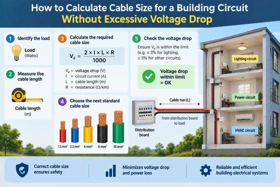

A circuit can be perfectly safe at the distribution board and still disappoint at the far end of a building. A pump that struggles to start, lights that dim when equipment cycles, or an EV charger that reports a supply fault can all point to the same overlooked issue: too much voltage lost in the cable.
This becomes more likely as buildings get larger, loads move farther from the panel, and circuits serve equipment with demanding starting or continuous currents. Selecting a cable only by its ampacity—the current it can carry without overheating—does not automatically solve it.
Cable sizing is therefore a balancing exercise. The conductor must carry the design current safely, survive the installation environment, coordinate with protective devices, and deliver adequate voltage at the load.
The method below gives a practical way to calculate and check voltage drop. It is an engineering guide, not a substitute for the electrical code, local design rules, manufacturer data, or a qualified designer’s judgment on a real installation.
🔌 01. What voltage drop actually means
Voltage drop is the reduction in voltage between the supply end of a circuit and its load end while current is flowing. Every conductor has resistance, so current passing through it produces a voltage loss.
Think of voltage as pressure and the conductor as a long pipe. A short, wide pipe offers little opposition; a long, narrow one creates more loss. In electrical terms, longer cable and smaller conductors generally produce more drop.
The lost voltage is not simply missing. It is largely converted into heat in the conductors, expressed by the familiar relationship P = I²R.
🏢 02. Why buildings expose the problem
Branch circuits in a small room may be short enough that voltage drop is modest. Feeders crossing floors, running to outbuildings, rooftop equipment, garages, pumps, and remote panels can be many times longer.
A circuit may also be extended later without revisiting the original conductor size. What was acceptable for a nearby load can become marginal after a panel relocation or building addition.
Voltage drop is especially visible where a load’s performance depends strongly on its terminal voltage, rather than merely on whether a breaker remains closed.
📉 03. Effects at the load end
Resistive loads such as heaters generally produce less output at lower voltage. Incandescent lamps visibly dim. Electronic power supplies may compensate over a range, but can draw higher current or shut down if their input falls outside their specified range.
Motors deserve particular attention. Low terminal voltage can reduce available starting and running torque, while a loaded motor may draw unfavorable current and run hotter. The exact behavior depends on motor type, controls, and load, so motor data and local rules matter.
Voltage drop also wastes energy in the wiring. That loss may be small on lightly used circuits, but a continuously loaded feeder makes conductor resistance a meaningful operating consideration.
🧭 04. Start with the correct circuit path
Measure the electrical route, not the straight-line distance on a plan. Include vertical risers, tray routes, bends, basement runs, and the path from the actual source to the actual load.
For a simple single-phase two-wire circuit, current travels out on one conductor and returns on another. The voltage-drop loop therefore uses twice the one-way length.
For a three-phase circuit, the calculation convention differs because current flows between phase conductors. Using the wrong length convention is one of the quickest ways to produce a misleading result.
📏 05. Establish the design length
Write down the one-way route length first, then state clearly whether a formula expects one-way length or loop length. Never mix these conventions silently.
For example, a receptacle 45 m away through a building has a 45 m one-way route. A single-phase line-to-neutral calculation commonly uses 90 m of conductor path; a balanced three-phase formula commonly uses the 45 m one-way route with its own multiplier.
Allow reasonable installation slack where it is genuinely part of the route. Do not add arbitrary margins in one place and then add another hidden safety factor later.
⚡ 06. Identify the system configuration
The applicable voltage-drop equation depends on whether the circuit is DC, single-phase AC, or three-phase AC. It also depends on whether the load is line-to-line or line-to-neutral.
| System | Common simplified resistive form | Length convention |
|---|---|---|
| DC or single-phase, two-wire | Vd = 2 × L × I × R |
L is one-way length |
| Balanced three-phase | Vd = √3 × L × I × R |
L is one-way length |
In these forms, Vd is voltage drop, L is length, I is current, and R is conductor resistance per unit length. AC circuits often need impedance rather than resistance alone.
🔢 07. Determine the design current
Use the current the circuit is designed to supply, not only the nameplate current of one appliance. Load calculations can include demand factors, diversity, continuous-load treatment, motor rules, and future capacity requirements set by the governing code.
For a known single-phase load, a rough relationship is I = P / (V × PF), where PF is power factor. Three-phase loads use I = P / (√3 × V × PF). Efficiency may also be needed when starting from mechanical output power.
These equations help estimate current, but they do not replace a code-compliant load calculation. Use manufacturer input for equipment with unusual duty cycles, electronic controls, or high inrush.
🧱 08. Separate ampacity from voltage-drop sizing
Ampacity answers “will the cable overheat?” Voltage drop answers “will the load receive enough voltage?” Both checks are required, and either can control the final cable size.
A cable selected from an ampacity table may have adequate thermal capacity but excessive resistance over a long run. Conversely, a very large conductor may easily meet voltage-drop expectations but still require correct insulation temperature rating, termination compatibility, and fault protection.
Start with the minimum size allowed by ampacity and protection, then increase the conductor size until the voltage-drop result meets the project criterion.
🌡️ 09. Account for installation conditions
Conductor resistance changes with temperature. Copper and aluminum conductors have higher resistance when hot than at a cool reference temperature, so data-table temperature assumptions matter.
Ampacity is also affected by ambient temperature, grouping with other loaded circuits, enclosure conditions, thermal insulation, burial conditions, and cable construction. These are not voltage-drop details alone; they may change the starting conductor size substantially.
Use the resistance or impedance data for the actual conductor type and installation method whenever available. A generic value is suitable only for an early estimate.
🧲 10. Resistance is not the whole AC story
Alternating-current conductors have impedance, a combination of resistance and reactance. Reactance arises from the magnetic field around AC conductors and becomes more relevant in larger conductors, long runs, certain cable arrangements, and circuits with lower power factor.
A more complete AC expression is Vd = multiplier × L × I × (R cosφ + X sinφ). Here X is reactance and φ is the power-factor angle; the multiplier is 2 for a two-wire single-phase circuit and √3 for balanced three-phase.
For short, small building conductors at near-unity power factor, resistance-only estimates are often useful for screening. For final design of substantial feeders, use published AC impedance data or design software consistent with the installation.
📊 11. Choose a voltage-drop criterion
Electrical codes and project specifications do not all use the same voltage-drop limits. In some jurisdictions, commonly cited values are recommendations or design guidance rather than universal enforceable limits; other rules may be stricter for particular occupancies or equipment.
A project may set separate targets for a branch circuit, a feeder, and the combined route from service to utilization equipment. The key is to check the total path, not only the final branch circuit.
Use the governing local code, client specification, utility requirements where applicable, and equipment manufacturer requirements. Sensitive loads may justify a tighter design target than a general lighting or receptacle circuit.
🧮 12. Calculate allowable voltage loss
Convert the selected percentage limit into volts before choosing a conductor. The calculation is straightforward: allowable Vd = nominal voltage × allowable percentage / 100.
For a hypothetical 230 V circuit with a 3% design target, the allowed drop is 230 × 0.03 = 6.9 V. That voltage budget must cover the part of the system being assessed.
This step prevents a common error: comparing a calculated drop in volts to a percentage limit without converting one to the other.
🧾 13. Gather trustworthy conductor data
Resistance values may be listed in ohms per kilometre, ohms per thousand feet, or milliohms per metre. Confirm both the unit and the stated conductor temperature before inserting the number in an equation.
Do not assume all cables with the same nominal cross-sectional area have identical AC impedance. Material, stranding, conductor arrangement, and manufacturer data can cause differences that matter in close designs.
Keep units consistent from start to finish. If resistance is in ohms per kilometre, convert length to kilometres; if it is in ohms per metre, use metres.
✏️ 14. A single-phase worked example
Consider a hypothetical 230 V single-phase load drawing 20 A, located 40 m from its supply point. Assume a proposed copper conductor has a resistance of 1.15 Ω/km at the relevant operating condition, and use a resistance-only estimate.
The loop length is 80 m, or 0.080 km. The estimated drop is Vd = 2 × 0.040 km × 20 A × 1.15 Ω/km = 1.84 V.
The percentage drop is 1.84 / 230 × 100 = 0.8%, approximately. This proposed conductor passes a 3% circuit target in this simplified example, but its ampacity, termination rating, protective device, installation derating, and fault performance still require separate verification.
🔺 15. A three-phase worked example
Now consider a hypothetical balanced 400 V three-phase load drawing 32 A at a one-way cable length of 75 m. Suppose the selected conductor resistance is 0.73 Ω/km and reactance is neglected only for this preliminary illustration.
The estimated drop is Vd = √3 × 0.075 km × 32 A × 0.73 Ω/km = 3.03 V, approximately. As a percentage of 400 V, that is about 0.76%.
For a motor feeder, a final check should include power factor, reactance where relevant, motor starting conditions, and the actual source voltage. Balanced-load assumptions should not be carried into a design with major phase imbalance.
📐 16. Work backward to find minimum area
When using conductor resistivity rather than a table, a basic DC or resistance-only relation is R = ρL/A, where ρ is resistivity, L is conductor length, and A is cross-sectional area.
Rearranging the single-phase two-wire form gives A = 2 × ρ × L × I / Vd. This estimates the minimum area required for a selected allowable voltage drop.
It is a useful planning tool, not a complete final-selection method. Use the next available standard conductor size, then verify with manufacturer data and all other electrical design checks.
🪜 17. Select the next standard cable size
Calculated conductor area rarely matches a standard cable size exactly. Choose the next larger available size, then recalculate voltage drop using that size’s published resistance or impedance.
Do not round downward because the difference appears small. Installation temperature, connector resistance, future loading, and source-voltage variation can consume a narrow margin.
Upsizing conductors may require attention to lug ranges, gland sizes, conduit fill, bending radius, pulling tension, and the ability of terminals to accept the larger cable.
🔗 18. Include feeder and branch-circuit drop
A remote load may be supplied through a main feeder, a local distribution panel, and a branch circuit. Each segment drops voltage, and the equipment sees their combined effect.
Calculate each segment using the current actually carried by that segment. A feeder carrying many loads may have a different design current than the final branch circuit, so one percentage cannot simply be copied across the whole path.
Keeping a small voltage-drop budget for downstream circuits during feeder design prevents a remote branch circuit from becoming difficult to fix later.
🚀 19. Treat motor starting as a separate check
Induction motors can draw several times their running current during direct-on-line starting, though the actual value and duration depend on the motor and starting method. That temporary current can produce a much larger temporary voltage drop.
Excessive starting drop can reduce motor torque precisely when the driven load needs acceleration. It may also cause contactors to chatter or affect nearby lighting and controls.
Check manufacturer starting data, supply transformer capability, feeder impedance, and the starting method. Soft starters, variable-frequency drives, or different feeder arrangements may address a starting problem more effectively than conductor upsizing alone.
⚖️ 20. Consider power factor and load type
At low power factor, reactance contributes more strongly to AC voltage drop. This is why an impedance-based calculation is valuable for large motors, long feeders, and inductive loads.
Nonlinear electronic loads add another complication: harmonic currents can increase neutral loading in some systems and affect conductor losses. Their evaluation is a system-design issue, not something resolved by applying a single resistance formula.
For ordinary mixed building loads, calculate from credible demand current and then identify any individual equipment that needs a dedicated, more detailed assessment.
🧰 21. Connection resistance can defeat a good calculation
A cable calculation usually assumes sound terminations. Loose, damaged, contaminated, or incorrectly torqued connections add resistance at lugs, breakers, isolators, and splices.
That extra resistance creates local heating and voltage loss that a conductor-only calculation cannot predict. A thermal inspection may reveal a poor connection, but installation workmanship and specified torque procedures are the first defenses.
Never compensate for suspect connections by merely installing a larger cable. Correct the connection and investigate the cause.
🛡️ 22. Check protective devices and fault performance
Upsizing for voltage drop does not remove the need for proper overcurrent protection. The protective device must protect the conductors, and its characteristics must suit the load and starting conditions.
Long circuits can also have lower available fault current at the far end because conductor impedance limits fault current. Depending on the earthing arrangement and protective scheme, this can affect automatic disconnection performance.
Fault-loop impedance, short-circuit withstand, grounding or earthing conductor sizing, and coordination are specialized checks that should be completed under the applicable installation rules.
🏗️ 23. Copper and aluminum need different handling
Both copper and aluminum can be appropriate conductor materials when correctly selected and terminated. Aluminum generally needs a larger cross-sectional area than copper for the same resistance and ampacity objective.
Its terminations must be listed for aluminum, prepared as required by the manufacturer, and tightened correctly. Differences in expansion, oxide behavior, and connector requirements make casual material substitution unsafe.
Compare complete installed options: conductor size, cable weight, termination hardware, available space, and approved installation practice—not only the purchase price per metre.
🧪 24. Verify the installation after energization
Calculations are predictions based on assumptions. Commissioning can validate them by measuring voltage at the source and at the load while the representative load is operating.
A meaningful test records current at the same time, because a no-load voltage reading says little about conductor drop. Compare measured results with expected values while recognizing that supply voltage and load current naturally vary.
Unexpected results call for a methodical review of connections, conductor identity, route length, phase balance, loading, and supply conditions before changing equipment settings.
🚫 25. Avoid common calculation mistakes
- Using one-way length in a two-wire formula that requires the return path.
- Using nominal breaker rating instead of the calculated design current without justification.
- Mixing metres with resistance stated in ohms per kilometre.
- Applying a DC resistance value as a final AC result where reactance matters.
- Checking only the branch circuit and forgetting the upstream feeder.
- Selecting cable by voltage drop but never confirming ampacity, fault duty, or terminal suitability.
A clear calculation sheet with units, assumptions, conductor data source, and each segment shown separately catches many of these errors before installation.
🗂️ 26. Use a repeatable calculation workflow
- Identify supply voltage, phase arrangement, and load type.
- Determine code-compliant design current and the full electrical route.
- Select a preliminary conductor from ampacity and installation conditions.
- Choose the applicable voltage-drop criterion and convert it to volts.
- Use published resistance or impedance data with consistent units.
- Calculate each feeder and branch segment, then add applicable drops.
- Increase to a standard conductor size if necessary and repeat the checks.
- Document protection, terminations, fault performance, and commissioning measurements.
This sequence is faster and more reliable than guessing a large cable first, because it exposes which constraint actually controls the design.
🧠 27. Know when software or specialist review is needed
A hand calculation is excellent for straightforward circuits and for checking whether a software result is plausible. More complex work benefits from validated software and professional review.
Seek deeper analysis for parallel conductors, long underground feeders, large motor groups, generators, sensitive medical or data equipment, harmonic-rich loads, unusual earthing systems, or projects governed by detailed contractual specifications.
Software is only as reliable as its inputs. Confirm conductor data, installation arrangement, temperatures, diversity assumptions, and the calculation method rather than treating a printed report as proof.
✅ 28. The core principle: size for the whole electrical job
Good cable selection is not a single ampacity-table lookup and not a voltage-drop calculation in isolation. It is a coordinated decision involving load current, route length, conductor impedance, system type, installation conditions, protective devices, and the load’s tolerance for reduced voltage.
Use the correct circuit geometry, apply an appropriate equation with consistent units, and evaluate the complete route from source to equipment. Then verify the selected standard size against thermal, mechanical, termination, and fault-protection requirements.
The practical goal is simple: deliver usable voltage under realistic load while keeping the wiring safe, code-compliant, and maintainable over the life of the building.
Calculate voltage drop from the real path and real load, then choose the smallest standard cable that satisfies voltage performance and every other required safety check. That approach turns cable sizing from a rule-of-thumb guess into a defensible design decision. ⚡🏢🔧