
Electrical power systems do more than simply deliver energy from a generator to a machine. In alternating-current, or AC, systems, part of the electrical current may repeatedly move energy back and forth between the source and certain types of equipment without producing useful mechanical work, heat, or light.
This behavior is associated with reactive power.
Reactive power is especially common in facilities containing motors, transformers, compressors, pumps, welding equipment, and other inductive loads. Although reactive power is necessary for many devices to create magnetic fields, excessive reactive demand forces the electrical system to carry more current than would otherwise be required.
More current means greater losses in cables, transformers, switchgear, and other equipment. 🔥
One of the most widely used solutions is a capacitor bank.
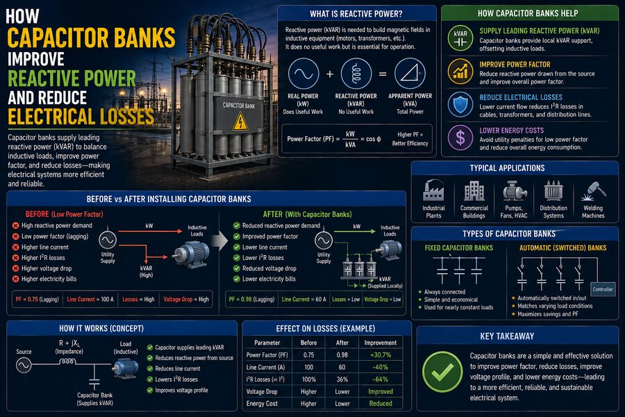
Capacitor banks supply capacitive reactive power close to the loads that need compensation. By doing so, they improve power factor, reduce current flowing through upstream conductors, release electrical-system capacity, and decrease resistive losses.
Understanding how this works requires distinguishing between real power, reactive power, and apparent power.
🔌 Real Power: The Power That Performs Useful Work
Real power, usually measured in watts or kilowatts, is the portion of electrical power that performs useful work.
Examples include:
- Turning a motor shaft
- Heating an electric furnace
- Operating lighting
- Running electronic equipment
- Producing mechanical output from a pump
Real power is commonly represented by the symbol:
P
and measured in:
W, kW, or MW
If an industrial motor consumes 80 kW of real power, that represents the energy actually being converted into useful output and unavoidable internal losses.
But an AC motor may require more electrical current than would be necessary for 80 kW alone.
That is because it also requires reactive power. 🧲
🌀 What Is Reactive Power?
Many AC loads are inductive.
Examples include:
- Induction motors
- Transformers
- Reactors
- Solenoids
- Magnetic ballasts
Inductive equipment requires magnetic fields to operate.
Energy is repeatedly stored in these magnetic fields and then returned to the electrical system during each AC cycle.
This back-and-forth exchange is associated with reactive power, represented by:
Q
Reactive power is usually measured in:
VAR, kVAR, or MVAR
Reactive power does not represent net energy consumed in the same way as real power, but it still contributes to the current flowing through electrical equipment.
That additional current has very real consequences. ⚠️
📐 Apparent Power Combines Real and Reactive Power
The electrical system effectively needs to accommodate both real and reactive components.
Their combined magnitude is called apparent power.
Apparent power is represented by:
S
and measured in:
VA, kVA, or MVA
For a simple sinusoidal system, the relationship is:
S² = P² + Q²
This relationship is often illustrated using the power triangle.
          Q
          |
          |\
          | \
          |  \ S
          |   \
          |____\
             P
Here:
- P = real power
- Q = reactive power
- S = apparent power
If reactive power increases while real power remains unchanged, apparent power also increases.
Because equipment ratings and line current are closely related to apparent power, excessive reactive power can place additional stress on the electrical system. 📊
📉 What Is Power Factor?
Power factor describes how effectively electrical current is being converted into useful real power.
For an ideal sinusoidal system:
Power Factor = Real Power ÷ Apparent Power
or:
PF = P / S
A power factor close to 1.0 means the electrical system is using current efficiently.
A lower power factor means more current is required to deliver the same amount of useful real power.
For example, imagine a load consuming:
100 kW
At a power factor of 1.0, the apparent power is:
100 kVA
At a power factor of 0.80, however:
S = 100 / 0.80 = 125 kVA
The electrical system must therefore carry more apparent power to deliver the same 100 kW of useful power.
That generally means more current. ⚡
🔥 Why Extra Current Causes Electrical Losses
Conductors have resistance.
Whenever current flows through resistance, electrical energy is converted into heat.
The resistive loss is approximately:
P_loss = I²R
where:
- I = current
- R = resistance
- P_loss = resistive power loss
Notice that current is squared.
This means relatively small reductions in current can produce meaningful reductions in losses.
For example, if current falls by 10%, resistive losses become approximately:
0.9² = 0.81
or about 81% of the original value, assuming resistance remains the same.
That corresponds to roughly a 19% reduction in I²R losses in that conductor.
This is one of the main reasons power-factor correction can improve system efficiency. 🔥➡️⚡
🔋 How Capacitors Help
Capacitors behave differently from inductive loads.
An inductive load tends to draw lagging reactive power.
A capacitor supplies leading reactive power.
When installed near an inductive load, the capacitor’s reactive contribution partially offsets the reactive power that would otherwise need to come from the upstream electrical source.
Suppose a motor requires:
100 kW of real power
and:
75 kVAR of inductive reactive power
Without compensation:
S = √(100² + 75²)
S = 125 kVA
Now suppose a capacitor bank supplies:
50 kVAR
locally.
The upstream system then needs to supply only:
75 – 50 = 25 kVAR
of reactive power.
The new apparent power is:
S = √(100² + 25²)
which is approximately:
103 kVA
The motor is still performing the same useful work, but the upstream system carries substantially less apparent power and therefore less current. 📉
🏭 What Is a Capacitor Bank?
A capacitor bank is a group of capacitors connected together to provide a desired amount of reactive-power compensation.
Capacitor banks may be installed at:
- Individual motors
- Motor control centers
- Distribution panels
- Main switchboards
- Industrial substations
- Utility substations
Their rating is commonly expressed in:
kVAR
For example, a facility may use a:
300 kVAR capacitor bank
to improve its overall power factor.
Depending on the application, capacitor banks may be fixed or automatically switched in steps. ⚙️
🎯 Capacitors Supply Reactive Power Locally
This is the central idea behind capacitor-bank compensation.
Without capacitors:
Utility/source → supplies real power + reactive power
With capacitors near the load:
Utility/source → supplies mostly real power + remaining reactive power
while:
Capacitor bank → supplies part of the reactive power locally
The inductive equipment still needs reactive power.
The capacitor bank does not eliminate that requirement.
Instead, it reduces how much reactive power must travel through upstream cables, transformers, and distribution equipment.
That reduces current in those parts of the system. 🔄
📉 Reduced Current Means Lower Cable Losses
Suppose a three-phase load draws a high current because its power factor is poor.
After capacitor compensation, the real power remains the same, but the line current decreases.
Since conductor losses are proportional to I²R, lower current produces lower heating losses.
This can result in:
- Reduced cable heating
- Lower transformer copper losses
- Improved energy efficiency
- Reduced voltage drop
- More available system capacity
The actual savings depend on where the capacitors are installed.
If capacitors are placed close to the load, reactive current can be prevented from flowing through a larger portion of the upstream network.
That often provides greater loss reduction than correcting power factor only at a distant central location. 📍
⚡ Capacitor Banks Can Improve Voltage
Current flowing through electrical-system impedance causes voltage drop.
When reactive current is high, voltage at the end of a feeder may fall more than desired.
By reducing upstream reactive-current flow, capacitor banks can help reduce voltage drop.
This may improve voltage conditions for equipment such as:
- Motors
- Process machinery
- Lighting systems
- Distribution panels
Utilities also use shunt capacitor banks on distribution and transmission systems to support voltage and manage reactive-power flow.
However, capacitor installation must be carefully engineered because excessive compensation can push voltage too high under light-load conditions. 📈
🏗️ Capacitor Banks Release Transformer and Cable Capacity
Transformers and conductors are limited partly by the amount of current or apparent power they can safely handle.
Suppose a transformer is heavily loaded because a facility operates with poor power factor.
Some of the transformer’s capacity is effectively being used to carry reactive power.
If power factor is corrected, the same real power can be delivered with lower kVA demand.
This may free capacity for additional useful loads without immediately replacing the transformer.
Similarly, feeders and switchgear may experience lower current after correction.
This is sometimes described as releasing system capacity. 🔓
It does not increase the physical rating of the equipment, but it allows more of that rating to be used for real-power delivery.
💰 Power-Factor Correction Can Reduce Utility Charges
Some commercial and industrial electricity tariffs penalize customers for poor power factor or high reactive-power demand.
The exact billing method varies by utility and location.
Charges may be based on:
- Maximum kVA demand
- Reactive energy
- kVAR demand
- Power-factor penalties
- Adjusted demand calculations
Improving power factor with capacitor banks can therefore reduce certain utility charges in addition to reducing physical system losses.
However, a financial analysis should always use the actual tariff applicable to the site.
Residential customers typically do not install capacitor banks merely to reduce their ordinary electricity bill because billing structures and load characteristics are very different. 💵
🔄 Fixed Capacitor Banks
A fixed capacitor bank remains connected continuously while the associated circuit is energized.
Fixed banks are suitable when reactive demand is relatively stable.
For example, a large motor that operates at nearly constant load for many hours may have a fixed capacitor installed near it.
Advantages include:
- Simple design
- Lower cost
- Minimal control complexity
But fixed compensation can become problematic if the load frequently turns off.
If the capacitor remains energized while inductive demand disappears, the system may become overcompensated. ⚠️
🤖 Automatic Power-Factor Correction Banks
Facilities with rapidly changing loads often use automatic power-factor correction, or APFC, systems.
Instead of using one fixed capacitor size, the bank is divided into steps.
For example:
25 kVAR
25 kVAR
50 kVAR
50 kVAR
100 kVAR
A controller continuously monitors electrical conditions.
As reactive demand changes, it switches capacitor stages on or off to maintain a target power factor.
The sequence might look like:
Load increases → reactive demand rises → controller adds capacitor steps
and later:
Load decreases → reactive demand falls → controller disconnects capacitor steps
This prevents unnecessary overcompensation while maintaining efficient operation. 🤖⚡
📊 Calculating the Required Capacitor Size
Engineers can estimate the required capacitor-bank rating using the existing and desired power factors.
A commonly used relationship is:
Q₍c₎ = P(tan φ₁ – tan φ₂)
where:
- Q₍c₎ = required capacitor reactive power
- P = real power
- φ₁ = phase angle at the original power factor
- φ₂ = phase angle at the desired power factor
Since:
Power Factor = cos φ
the power-factor values can be converted into corresponding phase angles.
Suppose a facility uses:
500 kW
at:
0.75 power factor
and wants to improve to:
0.95
The required capacitor rating can be calculated from the difference in reactive-power requirements.
In practical installations, engineers also consider load variation, harmonics, switching steps, voltage, and future expansion rather than relying on a single theoretical calculation. 🧮
⚠️ Why a Power Factor of Exactly 1.0 Is Not Always the Goal
It may seem logical to correct every facility to a perfect power factor of 1.0.
In practice, engineers often target something slightly below unity, depending on system requirements and utility rules.
Why?
Because loads change.
A capacitor bank sized perfectly for peak load may supply too much reactive power when demand decreases.
This can produce a leading power factor, where capacitive reactive power exceeds inductive demand.
Overcompensation may contribute to:
- Voltage rise
- Unfavorable utility conditions
- Resonance concerns
- Control instability
Automatic step switching helps manage this issue. ⚖️
🌊 Harmonics Can Complicate Capacitor-Bank Design
Modern electrical systems often contain nonlinear loads such as:
- Variable-frequency drives
- Rectifiers
- UPS systems
- Switching power supplies
- Industrial power electronics
These devices can create harmonic currents.
Capacitors interact with the inductance of transformers and conductors.
Under certain conditions, the combination can form a resonant circuit near a harmonic frequency.
Instead of improving system performance, an improperly designed capacitor bank could amplify harmonic currents or voltages. 🚨
This may cause:
- Capacitor overheating
- Fuse operation
- Excessive current
- Equipment stress
- Premature capacitor failure
For facilities with significant harmonic distortion, engineers often perform a harmonic study before installing large capacitor banks.
🛡️ Detuned Capacitor Banks
One solution for harmonic-rich systems is the detuned capacitor bank.
These systems place reactors in series with the capacitor stages.
The reactor-capacitor combination is selected so that the circuit avoids dangerous resonance with dominant system harmonics.
Detuned banks can still provide power-factor correction while reducing the likelihood that the capacitors attract excessive harmonic current.
More severe harmonic conditions may require filters specifically designed to control harmonic frequencies.
This demonstrates why capacitor banks should not simply be added based on kVAR calculations alone. 🔧
🔌 Switching Capacitors Creates Transients
Capacitors can draw high transient currents when they are energized.
Switching a capacitor bank can therefore produce:
- Inrush currents
- Voltage transients
- Contact wear
- Stress on capacitors
Large systems may use specialized:
- Capacitor-duty contactors
- Switching devices
- Pre-insertion components
- Protection equipment
- Control sequences
Some applications use thyristor-switched capacitor systems when very rapid reactive-power compensation is required.
Proper switching design improves both reliability and capacitor life. ⚙️
🔥 Capacitor Banks Also Have Losses
Although capacitors reduce losses elsewhere in the network, they are not perfectly lossless devices.
Real capacitor banks experience small dielectric and conductor losses.
Reactors, contactors, protective devices, and associated equipment can also introduce losses.
However, in correctly designed installations, the reduction in upstream losses and demand can outweigh these relatively small internal losses.
Engineering decisions should therefore be based on the complete system rather than assuming ideal components.
🧯 Protection Is Essential
Capacitor banks store electrical energy.
They require appropriate protection and safe-discharge arrangements.
Depending on the system, protection may include:
- Fuses
- Circuit breakers
- Overcurrent relays
- Unbalance protection
- Overvoltage protection
- Discharge resistors
- Thermal monitoring
After a capacitor is disconnected, it can retain dangerous voltage for a period of time.
Discharge resistors help reduce the stored voltage to a safer level.
Maintenance personnel must follow established isolation, testing, and lockout procedures before working on capacitor equipment. 🛡️
🏢 Where Should Capacitors Be Installed?
There are several possible locations.
1. At Individual Loads
A capacitor may be installed directly near a large motor.
Advantage: Reactive current is reduced through nearly the entire upstream circuit.
Challenge: The capacitor must generally coordinate with operation of the motor.
2. At Distribution Boards
Several nearby loads may be compensated together.
Advantage: Good compromise between localization and equipment cost.
3. At the Main Switchboard
A centralized automatic bank corrects the facility’s overall power factor.
Advantage: Easier centralized control and maintenance.
Limitation: Reactive current may still flow through internal downstream feeders before reaching the central bank.
The best arrangement may combine several approaches. 📍
🏭 Example: An Industrial Facility
Imagine a factory operating several motors, pumps, and compressors.
The plant uses:
1,000 kW of real power
at a power factor of:
0.75
Its apparent-power demand is approximately:
1,333 kVA
After installing an appropriately designed capacitor bank, the power factor improves to:
0.95
The new apparent-power requirement becomes approximately:
1,053 kVA
The plant is still using 1,000 kW of real power.
Its machines are still performing essentially the same productive work.
But the upstream system now carries substantially less apparent power and current.
Benefits may include:
- Lower feeder current
- Reduced I²R losses
- Less transformer loading
- Improved voltage profile
- More spare electrical capacity
- Potential reduction in utility demand charges
That is the practical value of reactive-power compensation. 🏭⚡
🚫 Capacitor Banks Do Not Reduce the Load’s Real Power
One important misconception should be avoided.
Installing capacitor banks does not normally make a 100 kW motor suddenly require only 80 kW of useful real power.
The machine still requires essentially the real power needed to perform its job.
What changes is the amount of reactive power supplied through the upstream system.
By reducing reactive-current flow, capacitor banks reduce associated losses and apparent-power demand.
Therefore, the primary savings come from:
lower electrical losses and improved system utilization, not from magically eliminating the useful energy required by equipment.
🌐 Capacitor Banks in Utility Power Systems
Capacitor banks are not limited to factories.
Electric utilities use them throughout distribution and transmission systems.
A utility may install capacitor banks:
- Along distribution feeders
- At substations
- Near large load centers
- On higher-voltage networks
These installations help:
- Support system voltage
- Reduce reactive-power flow
- Lower line losses
- Improve transmission capability
- Manage system power factor
Some banks are switched automatically according to voltage, reactive demand, time schedules, or centralized grid-control commands.
At utility scale, reactive-power management becomes an important part of maintaining stable and efficient grid operation. 🌐
🔄 Capacitors Are Only One Reactive-Power Solution
Capacitor banks are widely used because they are relatively simple and efficient, but they are not the only technology available.
Other reactive-power devices include:
- Synchronous condensers
- Static VAR compensators
- STATCOM systems
- Power-electronic compensation equipment
These alternatives may provide faster or more controllable reactive support.
However, they are often more complex and costly.
Conventional capacitor banks remain highly attractive when stepped or fixed reactive compensation is sufficient. 💡
📊 Why Monitoring Matters After Installation
Installing a capacitor bank is not the end of the engineering process.
Facilities can change over time.
Motors may be replaced, variable-frequency drives may be installed, production schedules may change, and harmonic levels may increase.
Monitoring should therefore evaluate parameters such as:
- Power factor
- kVAR demand
- Voltage
- Harmonic distortion
- Capacitor current
- Stage operation
- Temperature
- Capacitor failures
Periodic inspection can identify blown fuses, failed capacitor elements, damaged contactors, or ventilation problems.
A capacitor bank that was properly sized years ago may no longer be ideal after major plant modifications. 🔍
🎯 Final Takeaway
Capacitor banks improve electrical systems by supplying capacitive reactive power close to inductive loads.
Motors, transformers, and similar equipment require reactive power to establish magnetic fields. Without local compensation, this reactive demand must travel through upstream transformers, cables, and switchgear, increasing current even though it does not represent additional useful real power.
Capacitors partially cancel that inductive reactive demand. 🔋
As a result:
Reactive power from upstream decreases → apparent power decreases → line current decreases → I²R losses decrease.
The benefits can include improved power factor, lower cable and transformer losses, reduced voltage drop, released system capacity, better voltage support, and potentially lower utility charges. ⚡📉
However, capacitor banks must be engineered carefully. Excessive compensation can cause leading power factor and voltage problems, while harmonics can create dangerous resonance conditions. Switching transients, protection, discharge requirements, and changing load patterns must also be considered.
The key lesson is that capacitor banks do not create free energy and do not eliminate the useful real power consumed by equipment.
Instead, they make the electrical network carry that real power more efficiently by reducing unnecessary reactive-current flow.
That is why capacitor banks remain one of the most practical and widely used tools for improving the efficiency and capacity of AC electrical power systems. ⚡🏭🔋