
A modern power grid carries enormous amounts of electrical energy across generators, substations, transformers, transmission lines, distribution feeders, and millions of customer connections. ⚡🏙️ Most of the time, electricity flows through this network continuously and almost invisibly.
But occasionally something goes wrong.
A tree branch may fall onto a power line. 🌳 Lightning may strike a transmission conductor. A cable may be damaged underground. Insulation inside a transformer can deteriorate. Equipment can fail, or two conductors that should remain separated can accidentally touch.
These events can create an electrical fault.
A fault can cause currents many times higher than normal operating levels, dangerous voltages, equipment damage, fires, instability, and widespread outages if it is not removed quickly.
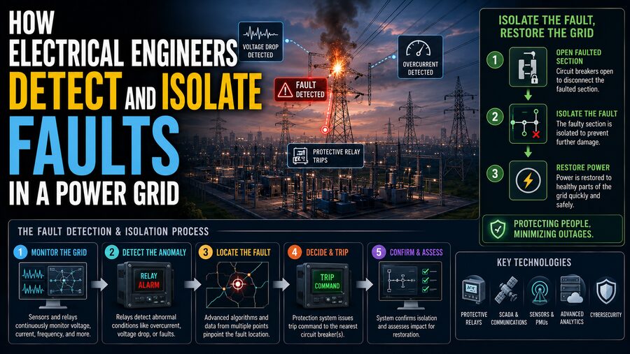
Electrical engineers therefore design power grids with sophisticated protection systems that continuously monitor the network.
Their job is to perform three essential tasks:
Detect the fault → Determine where it is → Disconnect only the affected section
The process may happen in a fraction of a second. 🛡️⚡
🔥 What Is an Electrical Fault?
Under normal conditions, electrical current follows intended paths through conductors and equipment.
A fault occurs when an abnormal electrical connection or condition changes that current flow.
Examples include:
- One phase touching ground
- Two phases contacting each other
- Three phases becoming short-circuited
- A conductor breaking
- Equipment insulation failing
- A cable being physically damaged
Some faults create enormous currents.
Others may produce relatively subtle abnormalities that require sensitive protection systems to detect.
The grid must distinguish between genuine faults and normal events such as motors starting, transformers energizing, or customers suddenly increasing their electricity use.
That distinction is one of the central challenges of power-system protection.
⚡ Why Short Circuits Produce Such Large Currents
Electrical networks contain impedance that limits current.
During normal operation, loads such as motors, lighting, electronics, and industrial machinery provide significant impedance.
A short circuit creates a path with much lower effective impedance.
According to the basic relationship:
Current = Voltage ÷ Impedance
if impedance suddenly becomes very small, current can become extremely large.
For example, a line normally carrying hundreds of amperes could experience fault current of several thousand amperes or more.
Such currents generate enormous thermal and mechanical forces.
Protection equipment must therefore operate rapidly.
🌩️ What Causes Grid Faults?
Power systems operate in difficult environments.
Faults can result from many causes, including:
- Lightning strikes ⚡
- Falling trees 🌳
- Strong winds
- Ice accumulation ❄️
- Animals contacting equipment
- Vehicle collisions with poles 🚗
- Excavation damaging underground cables
- Aging insulation
- Equipment manufacturing defects
- Contamination or moisture
- Human error
Engineers cannot prevent every possible fault.
Instead, they design the grid so that faults can be detected, contained, and cleared safely.
🧭 Different Types of Faults
Three-phase AC power systems can experience several common fault configurations.
🌍 Single Line-to-Ground Fault
One phase conductor accidentally contacts ground or grounded equipment.
This is one of the most common fault types on many power systems.
↔️ Line-to-Line Fault
Two phase conductors contact each other.
Large currents may flow between the phases.
🔺 Three-Phase Fault
All three phases become short-circuited.
This is less common but can produce extremely high symmetrical fault currents.
🌍🔄 Double Line-to-Ground Fault
Two phases simultaneously become connected to ground.
Each type creates a different pattern of voltages and currents, which protection systems can analyze.
👀 Engineers Cannot Measure High-Voltage Lines Directly
A transmission line may operate at hundreds of thousands of volts.
Protection electronics cannot simply connect their small measurement circuits directly to such conductors.
Instead, substations use measurement transformers and sensors.
Two especially important devices are:
🔄 Current Transformers — CTs
Current transformers produce a scaled representation of the current flowing through a high-power conductor.
For example, thousands of amperes on a transmission line may be represented by a much smaller current suitable for measurement equipment.
⚡ Voltage Transformers — VTs or PTs
Voltage transformers provide a safely scaled representation of high system voltage.
Modern grids may also use other electronic or optical measurement technologies.
These sensors provide the protection system with a continuous view of what the power network is doing.
🧠 Protective Relays Are the Grid’s Fast Decision Makers
The devices that interpret electrical measurements are called protective relays.
Historically, relays were electromechanical devices containing coils, disks, and moving components.
Modern protection systems usually use microprocessor-based digital relays.
A digital relay can continuously examine:
- Current
- Voltage
- Frequency
- Phase angle
- Impedance
- Direction of power flow
- Rate of change
Thousands of measurements can be processed every second.
If the measurements match the characteristic pattern of a fault, the relay can issue a trip command.
🔌 Circuit Breakers Actually Disconnect the Fault
The protective relay detects and decides.
The circuit breaker physically interrupts the electrical current.
A simplified protection sequence is:
Fault occurs → Sensors detect abnormal signals → Relay identifies fault → Relay sends trip signal → Circuit breaker opens
When the breaker opens, electrical contacts separate.
Interrupting high-voltage current is much harder than opening an ordinary household switch.
An electrical arc can form between separating contacts.
High-voltage circuit breakers therefore use specialized technologies to extinguish the arc and safely interrupt fault current.
⏱️ Why Protection Must Be Extremely Fast
Fault current can damage equipment rapidly.
Conductors heat according to the energy flowing through them.
Power-system faults can also create severe mechanical forces between conductors.
The longer a fault remains connected, the more damage it can cause.
High-speed transmission protection may operate within only a few electrical cycles.
At 50 Hz, one cycle lasts:
20 milliseconds
At 60 Hz:
16.7 milliseconds
Some protection decisions can therefore occur in only tens of milliseconds. ⚡⏱️
🎯 The Goal Is Selectivity
Simply disconnecting electricity whenever something unusual happens would be easy.
The difficult part is disconnecting only the equipment that actually needs to be removed.
Suppose a fault occurs on one distribution feeder.
A poorly designed protection system might disconnect an entire substation.
A well-coordinated system instead opens the breaker supplying the affected feeder while leaving neighboring feeders operating.
This principle is called selectivity or discrimination.
The objective is:
Small fault → Smallest practical outage
🧩 Power Grids Are Divided Into Protection Zones
Engineers divide substations and transmission systems into overlapping protection zones.
Individual zones may protect:
- Generators
- Transformers
- Busbars
- Transmission lines
- Distribution feeders
Circuit breakers form boundaries between many of these zones.
If a fault occurs inside one zone, the associated protection should disconnect that zone.
The zones often overlap slightly so there are no unprotected gaps.
This creates a layered defensive structure across the power grid.
📈 Overcurrent Protection Detects Excessive Current
One of the simplest forms of protection is overcurrent protection.
The relay asks:
“Is the current much higher than expected?”
If current exceeds a specified threshold, the relay may trip the breaker.
But engineers must choose the threshold carefully.
Current can become temporarily high during perfectly normal events.
For example:
- Large motors starting
- Transformers energizing
- Sudden load increases
Protection must tolerate acceptable temporary conditions while still responding quickly to genuine faults.
⌛ Time-Overcurrent Coordination
Not every overcurrent relay trips immediately.
Some use an inverse-time characteristic.
Generally:
Slight overcurrent → Longer delay
Very large fault current → Faster trip
This helps coordinate multiple protective devices along a feeder.
Imagine:
Substation breaker → Feeder → Local fuse → Customer equipment
If a fault occurs near the customer, the nearest protective device should ideally operate first.
If that protection fails, an upstream device can trip after a controlled delay.
This provides backup protection.
🌍 Ground-Fault Protection
A fault involving ground can sometimes produce currents different from ordinary three-phase short circuits.
Protection systems can detect unusual residual or zero-sequence currents that indicate current is flowing through an unintended ground path.
Ground-fault protection is important because many real-world faults involve damaged insulation contacting grounded equipment, structures, or earth.
Sensitive ground protection can sometimes detect faults that ordinary phase-overcurrent elements might not identify quickly enough.
🧮 Differential Protection Compares Current Entering and Leaving
Differential protection is one of the most powerful protection principles.
Imagine a transformer.
Current enters through one side and leaves through another.
After accounting for transformer ratio and expected behavior, the relay compares these currents.
During normal operation:
Current entering ≈ Current leaving
If a serious internal fault occurs:
Current entering ≠ Current leaving
The difference indicates that current is flowing somewhere it should not.
Conceptually:
Input current − Output current = Differential current
If the differential current becomes large enough, the relay can trip breakers surrounding the equipment.
Differential protection is commonly used for:
- Transformers
- Generators
- Busbars
- Large motors
- Transmission lines
🔍 Differential Protection Creates a Precise Zone
One major advantage of differential protection is that it can define a very specific protected region.
Consider current transformers installed on both sides of a transformer.
The protection zone lies between them.
A fault inside the zone produces a differential current.
A fault outside the zone may produce very high current, but the incoming and outgoing measurements should still balance appropriately.
This allows the relay to distinguish internal equipment faults from faults elsewhere on the grid.
📏 Distance Protection Estimates How Far Away a Fault Is
Transmission lines require another clever technique called distance protection.
A relay measures voltage and current and calculates an apparent electrical impedance:
Z = V / I
Transmission-line impedance generally increases with line length.
Therefore, the apparent impedance measured during a fault can indicate approximately how far along the line the fault occurred.
Conceptually:
Lower measured impedance → Fault likely closer
Higher measured impedance → Fault likely farther away
The relay does not literally measure physical distance with a ruler.
It estimates distance based on the electrical characteristics of the line.
🎯 Distance Relays Use Protection Zones
Distance protection commonly uses several operating zones.
For example:
Zone 1 may cover most of the protected line and operate very quickly.
Zone 2 may extend beyond the far end with a delay.
Zone 3 may provide more remote backup protection.
This staged approach allows fast local fault clearing while preserving backup protection if another relay or breaker fails.
Exact settings depend on the network.
➡️ Directional Protection Determines Which Way the Fault Lies
In complex grids, power can flow through several paths.
High current alone may not tell a relay whether the fault is upstream or downstream.
Directional relays use voltage and current phase relationships to determine the direction toward the fault.
This is particularly useful in:
- Ring networks
- Parallel feeders
- Meshed transmission grids
- Systems with distributed generation
Directional protection helps prevent healthy parts of the network from being disconnected unnecessarily.
📡 Communication Makes Protection Faster
Relays at opposite ends of a transmission line can communicate with one another.
Modern systems may use:
- Fiber-optic links
- Microwave communications
- Utility communication networks
The relays can exchange information about what each end of the line is measuring.
If both ends agree that a fault lies between them, they can trip extremely quickly.
This is often referred to broadly as pilot protection or line differential/communications-assisted protection, depending on the scheme.
🛰️ GPS Timing Allows Measurements to Be Synchronized
Modern power systems can use highly accurate time synchronization, often derived from satellite-based timing systems.
This allows measurements taken hundreds of kilometers apart to be compared using the same time reference.
Devices known as phasor measurement units, or PMUs, can measure synchronized voltage and current phasors.
These measurements help engineers monitor:
- Grid stability
- Oscillations
- Voltage angles
- Major disturbances
PMUs generally support wide-area monitoring and control rather than replacing the fastest local protective relays.
🔄 Automatic Reclosing Handles Temporary Faults
Many overhead-line faults are temporary.
Imagine lightning causing an electrical arc between a conductor and a nearby object.
The arc may disappear once the breaker opens.
If the line itself is undamaged, it may safely operate again.
For this reason, power systems often use automatic reclosing.
A simplified sequence is:
Fault detected → Breaker opens → Short delay → Breaker closes again
If the fault has disappeared, service continues.
If the fault remains, the protection may trip again and lock out the line.
Automatic reclosing can prevent temporary events from causing unnecessarily long outages.
🌳 Why Overhead Distribution Lines Often Reclose
Distribution networks frequently experience temporary disturbances from:
- Tree branches
- Lightning
- Animals
- Wind-blown debris
A recloser can interrupt the fault and later attempt to restore the circuit.
If the problem was temporary, customers may experience only a brief interruption.
If it is permanent—such as a broken conductor—the device eventually remains open until crews investigate.
🔥 Underground Cable Faults Are Often Different
Underground cable failures are less likely to disappear simply because power is briefly interrupted.
A damaged insulation layer or physically damaged cable usually remains damaged.
For this reason, reclosing practices for underground cable networks may differ from those for overhead systems.
Engineers adjust protection philosophy according to the characteristics of the equipment being protected.
🧯 Fuses Provide Simple Local Protection
Not every grid-protection device contains a computer.
Electrical fuses are still widely used.
A fuse contains an element designed to melt when excessive current flows for sufficient time.
When it melts, the circuit opens.
Fuses are:
- Simple
- Relatively inexpensive
- Reliable
They are common in distribution systems and equipment protection.
However, unlike a circuit breaker, a blown fuse generally must be replaced before service can be restored.
🔄 Coordination Between Fuses, Relays, and Breakers
Distribution engineers carefully coordinate protective devices.
Consider:
Substation relay → Recloser → Fuse → Distribution transformer
A fault near one customer should ideally cause the nearest appropriate protective device to operate.
The upstream devices remain available as backup.
Coordinating these devices requires studying their time-current characteristics.
Engineers plot how quickly each device operates at different current levels and adjust settings so the intended sequence occurs.
🚨 What if the Circuit Breaker Fails to Open?
Protection systems must also consider failure of the protection equipment itself.
Suppose a relay correctly detects a fault and commands a breaker to open.
But the breaker has a mechanical problem and remains closed.
A breaker-failure protection scheme can detect that fault current is still flowing.
It then trips additional nearby breakers to isolate the fault through a wider section of the network.
This causes a larger outage, but it prevents the fault from remaining energized indefinitely.
Reliability therefore comes from layers of backup.
🛡️ Primary and Backup Protection
Critical grid equipment often has more than one protection method.
There may be:
Primary protection — intended to clear the fault first.
Backup protection — operates if primary protection fails.
For an important transmission line, separate relay systems may even use different hardware or principles.
This reduces the possibility that one failure disables all protection.
🏭 Transformer Protection Requires Multiple Signals
Transformers are expensive and critical grid components.
Different transformer problems produce different electrical symptoms.
Protection may monitor:
- Differential current
- Overcurrent
- Ground faults
- Temperature
- Pressure
- Gas accumulation
Large oil-filled transformers can contain dedicated mechanical protection that detects internal conditions caused by developing faults.
A severe internal transformer fault may require breakers on multiple sides to open immediately.
🧲 Magnetizing Inrush Must Not Be Mistaken for a Fault
When a transformer is first energized, it can temporarily draw a large magnetizing inrush current.
The current can resemble an internal fault in magnitude.
Protection systems therefore use additional characteristics to distinguish normal transformer energization from genuine internal faults.
This illustrates an important challenge:
Fast protection must also be intelligent enough to avoid unnecessary trips.
A false trip can itself create a serious grid disturbance.
🚌 Busbar Faults Require Extremely Fast Isolation
A substation busbar connects multiple transmission lines, transformers, or feeders.
A fault on a bus can therefore be especially serious because many sources may feed current into it.
Bus differential protection compares currents from every circuit connected to the protected bus.
If they fail to balance appropriately, the system can identify an internal bus fault.
The protection may then open all breakers feeding that bus section.
Because bus faults can involve very high currents, speed is critical.
⚙️ Generator Protection Is Highly Specialized
Large power generators require sophisticated protection because numerous abnormal conditions are possible.
Protection systems may detect:
- Internal winding faults
- Ground faults
- Abnormal frequency
- Overvoltage
- Loss of excitation
- Reverse power
- Unbalanced currents
The objective is not simply to disconnect the generator for every unusual event.
Engineers determine which conditions require immediate trip and which can tolerate alarms or delayed action.
Generators are valuable assets, but leaving a serious fault energized can cause catastrophic damage.
🌐 Grid Frequency Can Reveal a Larger Problem
The power grid must continuously balance:
Electricity generated ≈ Electricity consumed
If a large generating station suddenly disconnects, generation may temporarily become lower than demand.
Grid frequency can begin to fall.
If too much generation disappears, protection systems may use underfrequency load shedding.
Selected loads are automatically disconnected to help restore balance.
This is different from clearing a short circuit, but it demonstrates another form of automatic grid protection.
The purpose is to prevent a local disturbance from becoming a total system collapse.
🧱 Power Grids Can Be Intentionally Divided
Under severe conditions, engineers may intentionally separate parts of the network into electrical islands.
Each island must maintain enough generation to support its local demand.
Intentional islanding can sometimes prevent a disturbance from propagating across a much larger interconnected grid.
The design is complex because generation, demand, voltage, and frequency must remain stable inside the separated region.
🌑 How Cascading Outages Can Develop
Suppose one transmission line trips.
Power that had been traveling through that line must find alternate paths.
Nearby lines may then become more heavily loaded.
If one of those also trips, the remaining network becomes even more stressed.
This can create a cascade:
Line trips → Power redistributes → Neighbor overloads → Neighbor trips → More redistribution
Protection systems are essential for equipment safety, but grid operators and automated controls must also prevent individual protective actions from escalating into widespread instability.
🖥️ SCADA Gives Operators a Live View of the Grid
Utilities use supervisory systems known as SCADA — Supervisory Control and Data Acquisition.
SCADA systems can display information including:
- Breaker status
- Voltage
- Current
- Power flow
- Alarms
- Transformer conditions
When protection operates, control-center operators can quickly see which breakers opened and which equipment became isolated.
SCADA also allows authorized operators to control some equipment remotely.
📜 Digital Relays Record Fault Events
Modern protective relays do more than trip breakers.
They can record detailed information surrounding a fault.
This may include:
- Current waveforms
- Voltage waveforms
- Relay-element operations
- Breaker commands
- Event timestamps
Engineers can later analyze these records to determine exactly what happened.
This is similar to an aircraft flight recorder—but for electrical disturbances. 📊
🔍 How Engineers Locate the Physical Fault
Knowing which line tripped does not always reveal exactly where repair crews should go.
A transmission line may be hundreds of kilometers long.
Fault-location methods can estimate the position using electrical measurements.
Approaches can include:
- Impedance-based calculations
- Measurements from both ends
- Traveling-wave analysis
- Line sensors
The control center might estimate that a fault occurred, for example, tens of kilometers from a particular substation.
Maintenance crews can then focus their inspection on a much smaller area.
🌊 Traveling-Wave Fault Location
A sudden transmission-line fault creates high-frequency electromagnetic waves that propagate along the line.
These are known as traveling waves.
Sensitive equipment can measure when these disturbances arrive at different locations.
Because electromagnetic waves travel extremely quickly, precise timing can help estimate fault location.
This technology can provide highly accurate fault-location information on some high-voltage transmission networks.
🚁 Physical Inspection Is Still Important
Electrical calculations help locate faults, but field crews may still need to visually inspect equipment.
Utilities can use:
- Ground patrols
- Helicopters 🚁
- Drones
- Thermal cameras
- Line sensors
They may look for:
- Broken insulators
- Fallen conductors
- Vegetation contact
- Burn marks
- Damaged towers
- Flashover evidence
Digital detection and physical inspection therefore work together.
🏙️ Distribution Automation Can Restore Customers Automatically
Modern distribution grids increasingly use remotely controlled switches.
Suppose one section of a feeder develops a permanent fault.
Automation may:
1. Open devices around the damaged section.
2. Isolate the fault.
3. Close another switch connecting healthy customers to a neighboring feeder.
The damaged section remains disconnected, while many customers regain power through an alternate route.
This concept is sometimes called fault location, isolation, and service restoration, or FLISR.
It can dramatically reduce outage duration.
🔀 Example of Automatic Distribution Restoration
Imagine a feeder supplying five zones:
A → B → C → D → E
A cable fault occurs in Zone C.
A smart system could:
Detect C fault ⚠️
Open switches on both sides of C ✂️
Keep A and B supplied from the original source
Supply D and E from an alternate feeder 🔄
Only Zone C remains without power while crews make repairs.
This is much more efficient than disconnecting all five zones.
☀️ Renewable Energy Makes Protection More Complex
Traditional grids were dominated by large synchronous generators that could supply very large fault currents.
Modern grids increasingly include:
- Solar farms ☀️
- Wind turbines 🌬️
- Battery systems 🔋
- Inverter-based generation
Power electronic inverters can behave differently during faults.
Their fault currents may be limited and controlled electronically.
This means some traditional protection assumptions may need to be reconsidered.
Engineers are developing adaptive and advanced protection methods for grids containing large amounts of inverter-based resources.
🏠 Distributed Generation Changes Power-Flow Direction
Traditional distribution networks often assumed electricity flowed:
Substation → Customer
Now a neighborhood may contain thousands of rooftop solar installations.
At certain times:
Customer solar → Distribution network
Power can therefore flow in both directions.
Directional relays, adaptive settings, and careful coordination may be required so protection still operates correctly.
The transition toward distributed energy makes grid protection an increasingly dynamic engineering discipline.
🔋 Microgrids Need Their Own Protection Strategy
A microgrid may normally connect to the larger utility network but continue operating independently during an outage.
Protection must behave differently depending on whether the microgrid is:
Grid-connected or islanded.
Fault-current levels and directions may change significantly between those two conditions.
Engineers may therefore use adaptive relays that automatically change settings based on operating mode.
🧪 Protection Systems Are Tested Before They Are Trusted
A relay may be mathematically sophisticated, but utilities cannot simply install it and hope it works.
Protection engineers perform extensive testing.
They may inject simulated currents and voltages into the relay and verify that it:
- Trips when required
- Remains stable for external faults
- Operates within the specified time
- Sends correct breaker commands
- Communicates correctly with other relays
Entire protection schemes may also be tested using real-time power-system simulation.
📐 Engineers Perform Short-Circuit Studies
Before setting protective relays, engineers calculate potential fault currents throughout the network.
A short-circuit study estimates how much current could flow for faults at different locations.
This helps engineers choose:
- Circuit breaker interrupting ratings
- Relay pickup values
- CT specifications
- Protection coordination
If equipment is not rated for the available fault current, it may not safely interrupt the fault.
Short-circuit analysis is therefore a fundamental power-system design task.
🔗 Protection Coordination Is a Grid-Wide Problem
Relay settings cannot be chosen independently.
Changing one relay can affect how it coordinates with devices elsewhere.
Engineers study the entire network.
They must balance:
Speed + Selectivity + Sensitivity + Reliability
These goals can compete.
A relay set too sensitively might trip unnecessarily.
A relay set too conservatively might fail to detect a weak fault.
A relay operating too slowly can allow excessive damage.
Power-system protection is therefore an optimization problem as much as a detection problem.
🛡️ Dependability and Security Mean Different Things
Protection engineers often think about two important qualities.
Dependability means the protection should operate when it is supposed to.
Security means it should avoid operating when it is not supposed to.
A relay that never trips is secure from false operation—but useless.
A relay that trips for every unusual signal is highly responsive—but unreliable.
Good protection must achieve both.
⚠️ Cybersecurity Has Become Part of Grid Protection
Modern relays and substations increasingly communicate digitally.
That creates tremendous operational benefits but also introduces cybersecurity requirements.
Utilities protect critical systems using measures such as:
- Network segmentation
- Authentication
- Access controls
- Monitoring
- Secure configuration
Protection commands must be trustworthy because opening or closing major circuit breakers can affect thousands of customers.
Cybersecurity is therefore becoming increasingly integrated with traditional electrical protection engineering. 🔐⚡
👷 After Isolation, Crews Repair the Problem
Automatic protection can isolate a fault, but it cannot repair a snapped conductor or failed transformer.
Once the faulty section is safely de-energized, utility crews can investigate and repair the equipment.
Depending on the problem, they may:
- Replace an insulator
- Repair a cable
- Remove vegetation
- Replace a transformer
- Reconnect a conductor
Before re-energizing, crews confirm that the equipment is safe.
The system can then gradually be returned to normal operation.
🧩 A Simplified Fault-Clearing Example
Imagine lightning strikes a high-voltage transmission line. ⚡
A simplified sequence might be:
1. Lightning causes an electrical flashover.
2. Fault current rises rapidly.
3. CTs and VTs measure abnormal currents and voltages.
4. Protective relays determine that the fault lies on the transmission line.
5. Relays command breakers at both ends to open.
6. Breakers interrupt the fault current.
7. The faulted line becomes electrically isolated.
8. Automatic reclosing may be attempted if appropriate.
9. If the fault persists, the line remains out of service.
10. Operators receive alarms and fault-location information.
All of the initial protection steps may happen faster than a person could consciously react.
🧠 The Grid Uses Layers of Defense
A reliable protection system rarely relies on one sensor or one relay.
Instead, it uses layers:
Sensors → Primary relay → Circuit breaker → Backup relay → Breaker-failure protection → Remote backup → Grid control systems
If one layer fails, another may still contain the problem.
This layered architecture is one reason large power networks can survive thousands of individual faults every year without collapsing.
✅ Final Thoughts
Electrical engineers protect modern power grids by continuously monitoring the electrical behavior of generators, transformers, transmission lines, substations, and distribution feeders. ⚡🏙️
When a fault occurs, current and voltage patterns change.
Current transformers, voltage sensors, and other measurement devices capture those changes. Protective relays analyze the signals and determine whether the event represents a dangerous fault.
Different protection principles solve different problems:
Overcurrent relays detect excessive current.
Ground-fault protection identifies abnormal current flowing toward ground.
Differential relays compare current entering and leaving protected equipment.
Distance relays estimate the electrical distance to transmission-line faults.
Directional relays determine which direction the fault lies.
Communication-assisted protection allows relays at distant substations to coordinate almost instantly.
Once a fault is identified, circuit breakers isolate the affected section—often within fractions of a second. 🛡️
Modern grids then go further.
Automatic reclosing can recover from temporary faults. Distribution automation can isolate damaged sections and restore healthy customers through alternate paths. SCADA systems inform operators, digital relays record disturbance data, and sophisticated fault-location technologies help repair crews find the physical problem.
The central philosophy of grid protection is beautifully simple:
Detect quickly → Isolate selectively → Keep everything else operating → Restore service safely.
The engineering required to achieve that goal is anything but simple.
Behind every apparently uninterrupted electricity supply is a vast invisible protection network constantly measuring, comparing, communicating, and preparing to act.
When something suddenly fails somewhere on the grid, that protection system may have only milliseconds to decide what happened—and disconnect exactly the right piece of equipment before a local fault becomes a much larger disaster. ⚡🔍🛡️