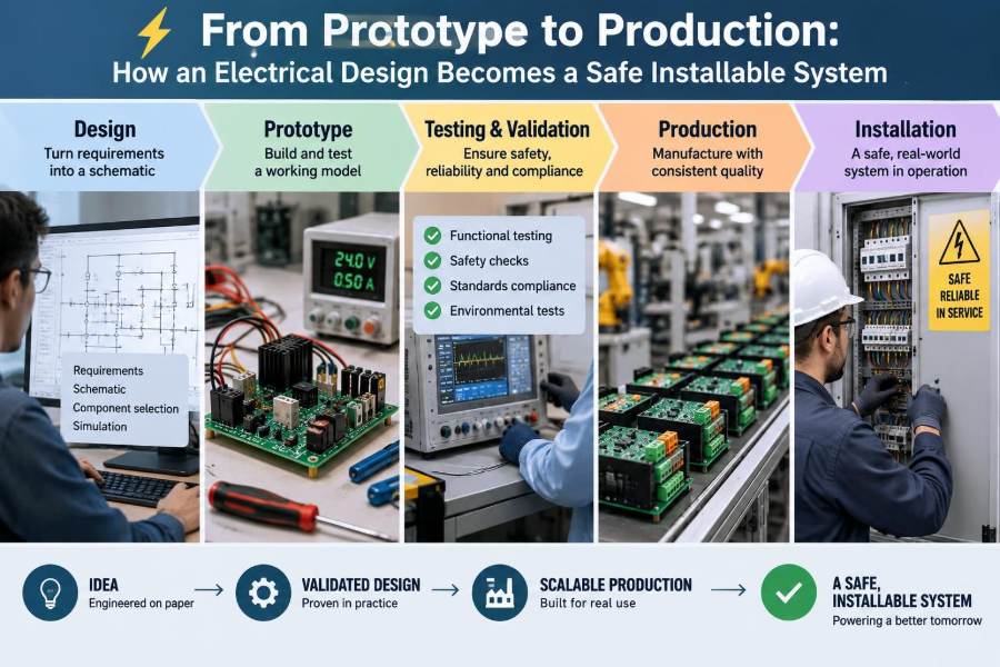

A prototype on a bench can be deceptively convincing. The LEDs light, a motor turns, a display responds, and the power supply shows a comfortable current reading. It is tempting to see that moment as the finish line.
But a product that works once under supervision is not automatically a product that can be installed in a factory, a home, a vehicle, or an outdoor enclosure. Real installations bring heat, vibration, wiring mistakes, mains transients, moisture, untrained users, service technicians, and years of wear.
The journey from prototype to production is therefore not simply a matter of ordering a printed circuit board in larger quantities. It is a structured process of turning electrical intent into something that can be built repeatedly, inspected confidently, used predictably, and maintained safely.
For students, this process explains why production schematics often look more disciplined than lab circuits. For working engineers, it is a reminder that every connector, clearance, label, and test point carries a design decision.
🧭 A Prototype Proves an Idea, Not a Product
A prototype answers a focused question: can this circuit perform the intended function? It may demonstrate a control algorithm, validate a sensor choice, or show that a converter can deliver enough power under a limited test condition.
A production design must answer many additional questions. Can a technician assemble it without interpretation? Can a customer connect it incorrectly without creating a shock, fire, or equipment hazard? Can the system tolerate expected supply variation and environmental stress?
Functional success is only one requirement. A safe installable system combines function with electrical safety, mechanical integrity, electromagnetic compatibility, manufacturability, traceability, and serviceability.
📋 Start With Requirements That Can Be Verified
Vague statements such as “runs from a 24 V supply” or “works outdoors” leave critical decisions unresolved. Production requirements need conditions, limits, and a way to verify compliance.
For example, a useful power requirement defines nominal voltage, allowable operating range, reverse-polarity exposure if relevant, maximum current, inrush behavior, and expected source type. “Outdoor” may need to define temperature range, water exposure, ultraviolet resistance, corrosion risk, and enclosure rating expectations.
- What must the system do during normal operation?
- What foreseeable faults must it survive or safely shut down under?
- Who installs it, and what tools or training can reasonably be assumed?
- Which applicable regulations, customer specifications, or certification routes govern the product?
Requirements do not make a design safe by themselves, but they prevent safety work from becoming guesswork late in the schedule.
⚖️ Separate Functional, Safety, and Compliance Needs
These categories overlap, but they are not interchangeable. A function requirement might state that a pump controller starts a motor on command. A safety requirement might state that a fault cannot leave the motor energized when an access panel is opened.
Compliance requirements come from the standards, regulations, installation rules, or market expectations relevant to the product. Their exact form depends on the equipment type and jurisdiction. A design team should identify the applicable framework early and confirm its interpretation with qualified compliance professionals where needed.
Trying to “make it compliant” after hardware is frozen often reveals expensive gaps: insufficient spacing, inaccessible protective earth terminals, unsuitable plastics, or a missing isolation barrier.
🗺️ Define the Installation Environment Early
The same electronics may be harmless on a lab bench and unreliable in a cabinet near welding equipment, a cold warehouse, or a vibrating machine. Environment changes the electrical and mechanical design simultaneously.
Consider the full path from shipping to end of life: storage temperature, transport shock, installation orientation, cable entry direction, altitude, cleaning chemicals, conductive dust, condensation, sunlight, and nearby sources of interference.
A small controller mounted inside a protected enclosure may need modest protection. The identical controller mounted externally may require sealed connectors, pressure equalization, corrosion-resistant hardware, and substantially different thermal planning.
🔌 Map Energy Flow Before Choosing Components
Follow energy from the incoming supply to every load and back through its return path. This simple exercise reveals where faults can occur and where protection belongs.
Draw the major domains: mains input, extra-low-voltage control, battery, motor drive, communication ports, field sensors, and protective earth. Mark where energy is converted, stored, switched, or exported through a connector.
Capacitors, inductors, batteries, and rotating loads deserve particular attention because they can retain or return energy after a supply is disconnected. A safe system considers not only where power enters, but also how it is isolated, discharged, and prevented from reaching vulnerable circuits.
🧱 Establish Electrical Boundaries and Isolation
An electrical boundary separates circuits that must not freely exchange hazardous energy. Isolation may be provided by a safety-rated transformer, isolated converter, optocoupler, digital isolator, relay, or another arrangement appropriate to the required barrier.
Isolation is not merely a symbol on a schematic. It includes the insulation system, component ratings, printed-circuit-board spacing, transformer construction, connectors, and the physical arrangement of conductors.
For example, an isolated communication interface can protect a low-voltage controller from ground-potential differences in a long cable run. But that benefit is weakened if cable shielding, mounting hardware, or another unintended route reconnects the two domains without analysis.
📏 Creepage and Clearance Are Physical Safety Features
Clearance is the shortest distance through air between conductive parts. Creepage is the shortest distance along an insulating surface. Both help prevent unwanted conduction, but they respond to different risks.
Air gaps can break down during voltage surges. Surface paths can become conductive when contaminated by moisture, dust, or residues. Required distances depend on factors such as working voltage, transient conditions, insulation class, material group, pollution degree, and the governing safety standard.
Do not rely on a generic spacing rule copied from an old board. Slots in the PCB can increase creepage, but only when their geometry and manufacturing tolerances are properly considered. Coating may help in some designs, yet it is not a casual substitute for correct spacing.
🛡️ Design Protection as a Coordinated Chain
There is rarely one component that “makes the input safe.” Effective protection is layered so that each element addresses a particular failure or disturbance.
A power entry might include a correctly rated fuse or electronic protection, surge suppression, reverse-polarity protection, inrush control, filtering, and a disconnecting means. Whether each item is needed depends on the source, load, fault energy, and intended installation.
The key question is coordination. A transient suppressor must not fail in a way that overwhelms the upstream protective device. A fuse must interrupt the available fault current safely. Conductors and connectors must tolerate the current until protection operates.
🔥 Size Conductors for Normal Load and Fault Conditions
Wire selection is more than matching an ampacity value. Conductor temperature depends on current, bundle density, insulation rating, ambient temperature, routing, termination quality, and whether the wire can shed heat.
Fault behavior matters too. A thin trace or wire may act like a fuse unintentionally, opening at an unpredictable location and leaving damaged insulation or conductive debris. Intentional protective devices should operate before ordinary interconnects become the weak link.
On PCBs, high-current paths require attention to copper thickness, trace width, vias, connector pins, and local hot spots. A wide trace that narrows at one via or terminal pad has not solved the bottleneck.
🌡️ Treat Thermal Design as an Electrical Requirement
Heat changes component lifetime, electrical resistance, switching losses, battery behavior, and measurement accuracy. A circuit that survives an open bench can overheat after being placed in a sealed enclosure beside other heat-producing equipment.
Build a heat budget from realistic operating modes, not only average power. A relay coil, regulator, motor driver, transformer, or resistor may see its worst heating during startup, stall, charging, or a blocked ventilation condition.
Measure temperatures on representative hardware, including terminals and nearby capacitors. Thermal images are useful for locating hot areas, but contact measurements and carefully placed sensors help validate actual component temperatures. Leave margin for a warm ambient environment and normal manufacturing variation.
⚡ Plan for Surges, Transients, and ESD
Supply lines and external cables are antennas for electrical disturbances. Motors, contactors, inductive valves, switching supplies, lightning-related events, and human handling can inject short, high-energy or high-voltage pulses.
A robust design distinguishes these threats. Electrostatic discharge, or ESD, is a brief event often associated with touch. Surge events can carry much more energy. Fast electrical transients may repeat in bursts. One protection device is seldom equally effective for all three.
Protection also needs a low-inductance route to the intended reference or return. A suppressor placed far from the entry point, connected by a long narrow path, may allow the protected circuit to see a much larger voltage than expected.
📡 Build EMC Into the Layout, Not Afterward
Electromagnetic compatibility, or EMC, means equipment can operate acceptably in its electromagnetic environment without creating unacceptable interference for other equipment. It includes both emissions and immunity.
Fast switching edges, switching converters, motor drives, clocks, and long cable runs can generate noise. Sensitive analog inputs, radios, reset lines, and communication interfaces can receive it. PCB layout controls the coupling between these sources and victims.
Keep high-current switching loops compact, provide deliberate return paths, separate noisy power areas from sensitive measurements, and treat connectors as boundaries where filtering or shielding may be required. A late-added ferrite can help, but it cannot reliably repair a fundamentally poor current-return layout.
🌍 Design Grounding and Bonding Deliberately
“Ground” can refer to a protective earth conductor, a circuit reference, a chassis bond, a cable shield, or a building earthing system. Confusing these roles causes both safety and noise problems.
Protective earth bonding provides a low-impedance path intended to support fault clearing and keep accessible conductive parts from becoming dangerously energized. It should be mechanically secure, clearly identified where required, and not dependent on a fragile signal connection.
Signal returns need controlled routing for performance. Cable shields may need termination choices based on frequency, EMC strategy, and installation context. There is no universal rule such as “connect every shield at one end”; the correct approach depends on the system and its environment.
🧩 Choose Components Beyond Their Headline Ratings
A 100 V MOSFET is not automatically appropriate for a 48 V motor circuit. Switching overshoot, avalanche energy, temperature, gate-drive conditions, repetitive stress, and layout parasitics can all reduce the usable margin.
Likewise, a connector’s current rating may be specified under particular temperature rise, conductor size, and mating conditions. A capacitor’s voltage rating does not guarantee sufficient ripple-current capability or lifetime at elevated temperature.
Review ratings in the conditions that matter: maximum supply, expected transient level, ambient temperature, load duty cycle, tolerances, and aging. Prefer components with documented sourcing and lifecycle support when the product is expected to be built or serviced for years.
🧪 Use Derating to Create Useful Margin
Derating means intentionally operating a component below a relevant limit, such as voltage, current, power, or temperature. It does not eliminate failure, but it makes normal variation and unexpected stress less likely to consume the entire design margin.
Good derating is evidence-based rather than ceremonial. A resistor near its power limit may be acceptable in a well-ventilated, controlled application but unsuitable in a hot sealed enclosure. An electrolytic capacitor may require more margin for temperature and ripple than a stable ceramic part in the same location.
Document the assumptions behind key margins. Future engineers need to know whether a choice was based on measured peak current, estimated airflow, a component pulse rating, or a specific fault scenario.
🖥️ Make the PCB Layout Manufacturable
A schematic expresses logical connectivity; a PCB expresses physical reality. Production layout must accommodate fabrication capability, assembly processes, inspection, test access, and repair where appropriate.
Clear silkscreen designators, consistent component orientation, adequate courtyard spacing, accessible programming pads, and sensible fiducials reduce assembly ambiguity. Avoid placing tall parts where they block test probes or prevent access to a fastener.
Manufacturing partners have different process limits for minimum drill size, solder-mask dams, panelization, and component placement. Early design-for-manufacture review is cheaper than discovering that a board is difficult to build after components have been purchased.
🔩 Treat Connectors, Terminals, and Cables as Safety Parts
Many field failures happen at the edges of a system: loose terminals, miswired connectors, inadequate strain relief, damaged cable jackets, and labels that disappear after cleaning.
Select connectors for voltage, current, wire size, mating cycles, environmental exposure, touch protection, and the likelihood of incorrect connection. Keying is valuable when two plugs could physically mate with the wrong port. When keying is impossible, physical separation, distinct connector families, and clear labeling reduce risk.
Provide strain relief so a pull on a cable is not transferred directly to solder joints or terminal clamps. Specify torque where screw terminals are used, and consider how installers will reach the terminal with real tools.
🧰 Design the Enclosure and Mechanics With the Circuit
An enclosure determines airflow, ingress protection, connector accessibility, cable bend radius, mounting, and the user’s exposure to live or moving parts. It is not packaging added after the electrical design is complete.
Metal enclosures can improve shielding and thermal spreading, but they require deliberate bonding and insulation around live parts. Plastic enclosures can simplify isolation but may need attention to flammability, ultraviolet exposure, stiffness, and static charge behavior.
Also consider installation mistakes: reversed mounting, blocked vents, missing gland seals, loose covers, and dropped screws. A design that remains safe when ordinary human errors occur is more valuable than one that works only under ideal assembly.
🧠 Plan for Human Factors and Clear Labels
Installers and service technicians work under time pressure, sometimes in poor lighting or awkward positions. Their decisions are shaped by connector placement, terminal order, wire color conventions, labels, drawings, and the tools available.
Use labels that state what matters at the point of action: supply type, terminal identity, polarity, protective earth location, torque where applicable, and warnings about hazardous energy. A label should not replace a safe design, but it can prevent predictable errors.
Documentation should show an unambiguous wiring diagram and installation constraints. If a particular external fuse, disconnect, cable type, or mounting orientation is necessary for safety, that requirement must be visible to the installer rather than buried in a design note.
🧯 Analyze Faults, Not Just Normal Operation
Normal operation is often the easiest state to understand. Safety engineering asks what happens when a component shorts, opens, drifts, disconnects, is installed backward, or receives an abnormal input.
Useful techniques include fault-tree analysis, failure mode and effects analysis, and structured “what if” reviews. The goal is not to predict every imaginable accident; it is to identify credible failure paths and determine whether the outcome is safe, detectable, or recoverable.
For instance, if a temperature sensor lead opens, should a heater continue operating, shut down, or enter a limited mode? The answer depends on the hazard. Treating sensor failure as an input value without considering its meaning can create dangerous behavior.
🔒 Build Safety Functions With Fail-Safe Behavior
Fail-safe behavior means a failure moves the system toward a safer condition when practical. For a valve that prevents overpressure, loss of control power may need to close it. For emergency lighting, loss of normal supply may need to turn it on.
There is no single “safe state” for all equipment. De-energizing a motor may be safer in one machine but hazardous in a lifting application if it removes a required holding function. The system context determines the correct response.
Independent shutdown paths, feedback contacts, watchdogs, plausibility checks, and monitored interlocks can improve confidence. Their value depends on independence: two functions sharing the same unprotected supply, connector, or software assumption may fail together.
🧾 Control Revisions and the Bill of Materials
A released design is a defined set of files, not just a PDF schematic. The manufacturing package normally includes controlled schematic and layout revisions, fabrication data, assembly drawings, a bill of materials, programming information, test instructions, and approved substitutions.
The bill of materials, or BOM, should identify components clearly enough to avoid accidental substitution of a safety-critical part. “Equivalent” is not always equivalent when package, insulation rating, flame class, surge capability, or termination material matters.
Use formal change control. Even a small capacitor replacement can affect inrush current, emissions, regulator stability, or approved construction. Traceable revisions allow a field issue to be connected to the exact hardware and process used to build it.
🏭 Design for Assembly, Inspection, and Test
Production quality is easier to achieve when the design exposes the right information. Test points, programming access, readable polarity marks, fixture locating features, and measurable reference nodes all reduce uncertainty.
Different stages catch different defects. Automated optical inspection can find visible solder and placement issues. Electrical test can reveal opens, shorts, wrong values, and functional failures. Final assembly inspection can confirm torque marks, labels, enclosure seals, and cable routing.
A practical test strategy separates faults quickly. If a board fails, technicians should be able to determine whether the issue lies in assembly, programming, calibration, external wiring, or the unit itself without improvised troubleshooting.
✅ Verify Against the Requirement, Then Validate the Use Case
Verification asks whether the design meets stated requirements. Validation asks whether those requirements and the resulting product solve the real user need. Both are necessary.
Verification may include measurements of voltage range, temperature rise, protective-device operation, insulation performance, emissions, immunity, and functional behavior. Validation may involve observing installation, reviewing service tasks, and testing realistic operating sequences.
A controller can verify successfully against an incomplete requirement and still fail validation because installers cannot distinguish its two similar connectors. That is why real use conditions should inform requirements from the beginning.
🧬 Test the System at More Than One Level
Board-level tests are efficient for basic electrical behavior, but they cannot fully represent enclosure effects, cable coupling, installation grounding, or interactions with real loads. System-level testing exposes issues that individual circuits hide.
Use a progression: simulate or calculate early, test subcircuits, test assembled boards, test the integrated product, and then test representative installation configurations. Each stage should refine the next rather than replace it.
When a failure occurs, preserve evidence before changing several variables at once. Record configuration, supply conditions, cable types, firmware revision, ambient conditions, and measurements. Reproducible failures teach far more than one-off fixes.
📚 Understand Standards Without Treating Them as a Checklist
Standards can define test methods, construction expectations, terminology, and safety objectives. They are essential tools, but simply ticking boxes without understanding the hazard can produce a brittle design.
Products may be subject to different requirements based on function, voltage, location, market, and installation type. A laboratory instrument, industrial controller, medical device, and household appliance should not be assumed to follow the same route.
Engage qualified safety and compliance specialists early for products that require formal evaluation or market access. This article describes engineering principles, not a substitute for applicable standards, local electrical codes, or professional certification decisions.
🔍 Conduct Reviews That Challenge Assumptions
Design reviews work best when reviewers are encouraged to ask uncomfortable but specific questions: What happens if this connector is unplugged? Where does this transient current return? Can the fuse clear the available fault current? How is this board tested after assembly?
Invite perspectives from hardware, firmware, manufacturing, test, field service, mechanical design, and installation teams. Each group sees failure modes that others may not encounter.
A review should produce actions, owners, and closure evidence rather than a vague statement that the design was “looked over.” Photos, measurements, revised drawings, and test results make the decision trail useful later.
🚧 Avoid Common Prototype-to-Production Traps
Several habits repeatedly create trouble when a bench design is moved into the field:
- Assuming a bench power supply represents a real electrical source.
- Adding protection only after failures appear, without checking coordination.
- Using connector ratings without considering wire size, heating, and installation access.
- Leaving test pads, programming headers, or live terminals accessible in the finished product.
- Depending on firmware alone to manage a hazard that also needs independent hardware protection.
- Making late component substitutions without rechecking electrical, thermal, and EMC consequences.
These are not signs of careless engineers. They are predictable consequences of treating production as a later phase rather than a design constraint from the first sketch.
🔧 Build a Feedback Loop From the Field
Production does not end the engineering process. Returns, installation questions, test yield data, supplier notices, and service observations reveal how the design behaves outside the development environment.
Classify issues carefully. A connector that is repeatedly miswired may indicate a documentation problem, a labeling problem, an installation training gap, or a product interface that invites error. Replacing the connector without understanding the mechanism may merely move the failure.
Feed confirmed lessons back into requirements, design rules, libraries, test fixtures, and review checklists. Over time, this creates organizational reliability rather than relying on individual memory.
🪜 A Practical Development Path
A disciplined path does not have to be slow. It prevents late discoveries from becoming crises.
- Define the intended use, environment, hazards, and verification criteria.
- Partition power and signal domains, then establish isolation and protection concepts.
- Select components and create schematic and layout with thermal, EMC, and manufacturing constraints in view.
- Review fault behavior, mechanics, installation, test access, and documentation before release.
- Build representative units, verify requirements, validate real use, and control changes into production.
Small teams can scale this process to their risk level. A low-voltage educational device needs less formality than high-energy industrial equipment, but both benefit from clear requirements and deliberate fault thinking.
🎯 The Core Principle: Design the Whole System
The critical transition from prototype to production happens when the engineer stops seeing the design as a circuit alone. It becomes a complete system of energy paths, insulation, software behavior, mechanics, cables, labels, installation instructions, tests, people, and maintenance.
Each layer supports the others. A well-sized fuse cannot compensate for an inaccessible terminal. Excellent PCB spacing cannot correct a misleading wiring diagram. Thorough testing cannot fully rescue requirements that ignored the real environment.
The strongest production designs make safe behavior the natural result of their construction and use. They reduce reliance on perfect assembly, perfect installation, and perfect operating conditions.
A safe installable electrical product is not a prototype with a case around it; it is a deliberately engineered system that anticipates how it will be built, connected, stressed, tested, and maintained. ⚡🛠️✅