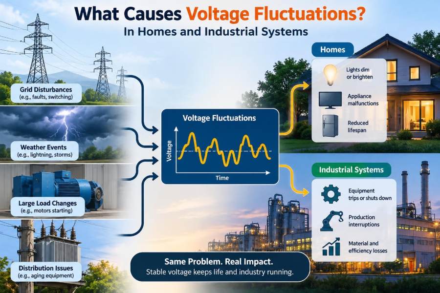

A ceiling light briefly dims when the air conditioner starts. A workshop motor slows under load. A production line controller resets without warning, even though the facility has not experienced a full power outage.
These are familiar symptoms of voltage fluctuation: a supply voltage that moves above or below its intended range, either for a fraction of a second or for a sustained period. The cause may be inside the building, somewhere on the distribution network, or at the point where both systems interact.
Voltage is not supposed to be perfectly motionless. Electrical loads change continuously, and power systems are designed to tolerate limited variation. Problems arise when the change is large, frequent, long-lasting, or reaches equipment that needs a stable supply.
Understanding what creates these changes helps homeowners avoid dangerous guesswork and helps industrial teams separate a utility-side event from a wiring, loading, control, or equipment problem.
⚡ What Voltage Fluctuation Actually Means
Voltage is the electrical potential difference that pushes current through a circuit. A nominal supply might be 120 V, 230 V, 400 V, or another value depending on the country and system arrangement, but the measured value naturally varies around that nominal level.
A voltage fluctuation is any meaningful change in that value over time. It can be gradual, such as lower voltage during a heavily loaded evening period, or abrupt, such as a dip when a large motor starts.
The useful question is not simply, “Did voltage change?” It is how far, for how long, how often, and under what operating condition?
📉 The Main Forms of Voltage Disturbance
Several events are casually called “fluctuations,” but they affect equipment differently. Clear terminology makes troubleshooting much more effective.
| Disturbance | What happens | Typical symptom |
|---|---|---|
| Undervoltage | Voltage remains below the expected operating range | Motors run hot or fail to start |
| Overvoltage | Voltage remains above the expected operating range | Lighting life is reduced; electronics may be stressed |
| Voltage sag or dip | A brief reduction in RMS voltage | Lights dim; contactors release; drives trip |
| Voltage swell | A brief increase in RMS voltage | Protection trips or sensitive supplies alarm |
| Interruption | Voltage drops very low or disappears | Equipment shuts down or resets |
| Transient | A very fast, often high-voltage spike | Electronic damage or unexplained failures |
RMS voltage is the effective voltage value used for AC power ratings. A short sag may not harm a resistive heater, yet the same event can reset a programmable controller or stop a variable-speed drive.
🔌 Why Loads Make Voltage Move
No real source has zero internal impedance. Wires, transformer windings, switchgear, and supply conductors all have resistance and reactance, which oppose current flow to some degree.
When current increases, voltage is lost across that impedance. In simplified form, the change is related to ΔV ≈ I × Z, where I is current and Z is impedance. Real AC systems require phase-angle considerations, but the principle remains: more current through a non-ideal path produces more voltage drop.
Think of a water pipe feeding several outlets. Opening a large outlet can reduce pressure at another outlet, especially if the pipe is long or narrow. Voltage behavior under changing load follows a similar practical pattern.
🏠 Starting Large Household Appliances
Many household loads draw far more current during starting than during normal operation. Compressor motors in refrigerators and air conditioners, water pumps, garage-door motors, and some power tools are common examples.
If the branch circuit, service conductors, or transformer has appreciable impedance, that inrush current creates a temporary voltage drop. A nearby lamp dimming when a refrigerator compressor starts can be a small, observable version of this effect.
Brief and minor dimming may occur without indicating a dangerous condition. However, pronounced dimming across much of a home, repeated motor hesitation, or a burning smell warrants assessment by a qualified electrician rather than repeated experimentation.
🧵 Undersized or Excessively Long Conductors
Conductor resistance increases with length and decreases with cross-sectional area. A long cable feeding a remote outbuilding, pump, welder, or machine may therefore experience considerable voltage drop, especially at high current.
Undersized wiring compounds the problem. It not only lowers the voltage available at the load but can also create excessive heating, which raises conductor resistance further.
Voltage-drop design is not merely about performance. A motor supplied at too low a voltage may draw unfavorable current, develop less starting torque, and overheat. The correct conductor size depends on load, distance, installation method, ambient conditions, protective device coordination, and applicable electrical rules.
⚖️ Unbalanced Loads in Single-Phase and Three-Phase Systems
In a split-phase residential supply, heavy loading on one leg can produce a different voltage behavior from the other leg. In a three-phase system, unequal phase loading can create unequal phase voltages, especially where supply impedance is significant.
Three-phase motors and drives are particularly sensitive to voltage unbalance. Even a modest voltage mismatch between phases can lead to unequal currents, extra heating, torque pulsation, and reduced motor life.
A facility should not assume that three equal-looking panel currents mean the system is healthy. Voltage must be measured phase-to-phase and, where relevant, phase-to-neutral while loads are operating.
🧷 Loose Neutral Connections: A High-Priority Fault
A loose, corroded, damaged, or poorly terminated neutral conductor can cause highly unstable voltages in systems that serve line-to-neutral loads. This is more serious than ordinary load-related voltage drop.
When the neutral connection becomes high resistance or opens, loads on different legs can effectively form a series path. Their voltages may then shift according to their impedances: one circuit can see low voltage while another sees dangerously elevated voltage.
Warning signs include lights that brighten when another load turns on, appliances behaving unpredictably, intermittent faults affecting several circuits, or unusual voltage readings at receptacles. A suspected loose service or panel neutral should be treated as an urgent professional-service issue.
🔥 Loose Connections and High-Resistance Joints
Not every voltage problem is a neutral problem. Loose terminals, worn breakers, damaged receptacle contacts, corroded lugs, and poorly made splices add resistance to a current path.
Under load, a high-resistance connection develops voltage drop and heat. The heating can worsen oxidation and loosen the connection further, creating a progressive failure mechanism.
Symptoms are often localized: a single outlet becomes warm, one machine loses power intermittently, or a particular feeder shows a larger voltage drop than similar feeders. Tightening energized equipment is not a do-it-yourself diagnostic method; safe inspection requires isolation procedures and appropriate competence.
🏘️ Utility Distribution and Neighborhood Demand
A home or factory is connected to a wider electrical network containing feeders, transformers, switches, and many other customers. When local demand rises, voltage on a distribution feeder can fall if the system is heavily loaded or far from regulation equipment.
Seasonal air-conditioning demand, electric heating, agricultural pumping, and clustered charging loads can all alter feeder loading patterns. Utilities manage voltage through transformer tap settings, regulators, capacitor banks, conductor design, and network planning, but no distribution system is immune to every localized condition.
If multiple nearby properties report the same pattern, especially at similar times, the source may be upstream. Logged voltage data is much more helpful to a utility than a report that power “felt weak.”
🌩️ Weather, Trees, and External Network Faults
Wind, ice, lightning, salt contamination, falling branches, and wildlife can disturb overhead lines and equipment. A fault may cause a sharp voltage sag before protective devices isolate the affected section.
Automatic reclosers may briefly open and re-energize an overhead circuit after certain temporary faults. Customers may notice a blink, reset clocks, or see a process controller restart even though service returns quickly.
Lightning-related transients are different from a sustained overvoltage. They are extremely brief, but their fast rise time can stress electronic inputs and insulation. Grounding, bonding, and correctly selected surge protective devices work together to reduce exposure; none turns every lightning event into a harmless one.
🏭 Motor Starting in Industrial Facilities
Large induction motors can draw substantial starting current while accelerating. The exact behavior depends on motor design, mechanical load, starting method, and supply stiffness, but the effect can be large enough to dip voltage on a shared bus.
A pump starting against high system pressure, a loaded conveyor, or a compressor with unfavorable restart conditions may accelerate slowly and extend the dip. Neighboring controls, lighting circuits, and contactors may all respond before the motor reaches normal speed.
Facilities commonly manage this with appropriate motor sizing, reduced-voltage starters, soft starters, variable-frequency drives, staged starting, or a stronger supply arrangement. The best choice depends on process needs and the motor’s required starting torque.
🌀 Reactive Power and Poor Power Factor
Motors, transformers, and other inductive loads require magnetizing current. This creates reactive power: power that moves back and forth between source and load rather than becoming useful mechanical output or heat.
Low power factor means more current is required to deliver a given amount of real power. Higher current increases losses and voltage drop in conductors and transformers, so poor power factor can worsen voltage regulation.
Capacitor banks or active power-factor equipment can help in suitable installations, but they require engineering. Incorrectly applied capacitors can create switching transients or interact with harmonics, particularly in facilities rich in electronic drives.
🎛️ Harmonics from Modern Electronic Loads
Many devices do not draw a smooth sinusoidal current. Variable-frequency drives, switch-mode power supplies, LED drivers, welders, rectifiers, and uninterruptible power supplies can draw current in pulses.
These non-sinusoidal currents create harmonics, frequency components above the fundamental supply frequency. Harmonics can distort voltage when they flow through source impedance and may overheat transformers, conductors, or neutral paths in certain system configurations.
Harmonics are not the same as ordinary voltage sag. A basic multimeter may show a plausible average or RMS value while missing waveform distortion. Power-quality analysis often needs an instrument designed to capture harmonics and events.
🔄 Rapidly Changing Industrial Loads
Some processes change electrical demand continuously rather than in one clean step. Arc furnaces, resistance welding, crushers, hoists, reciprocating compressors, and large cycling pumps can impose rapidly varying current on the supply.
The result may be repetitive voltage changes, visible lamp flicker, nuisance trips, or process instability. In an office connected near a welding bay, occupants may notice flicker long before a meter reveals the complete electrical pattern.
Mitigation can involve dedicated feeders, stronger transformers, process sequencing, energy storage, dynamic reactive-power compensation, or changes to the equipment duty cycle. A solution must address the measured mechanism, not merely the visible symptom.
💡 Why Lights Flicker
Incandescent lamps visibly respond to voltage changes because filament temperature and light output vary with input power. LED lamps may respond differently: a well-designed driver can ride through small variations, while a poor or failing driver may flicker noticeably.
Flicker is a useful clue but not a complete diagnosis. A light on one overloaded circuit may flicker because of local wiring, while lights throughout a building flickering together point more strongly toward a shared feeder, service, or utility source.
Dimmer compatibility, failing LED drivers, loose lamp bases, and control-system issues can also create flicker without a building-wide voltage problem. Observe which lights are affected and what equipment operates at the same moment.
🖥️ Why Electronics Reset Before Other Equipment Fails
Electronic power supplies convert AC input into regulated DC rails. Their internal capacitors provide only limited ride-through energy during a voltage dip.
A brief sag may be too short to stop a motor, but long enough for a controller, router, PLC, cash register, or computer power supply to lose regulation and reset. This explains why “the power never went out” can still be true from a lighting perspective while a digital process loses its state.
Critical systems may need equipment with suitable ride-through capability, properly specified UPS support, or DC buffering. A small consumer UPS is not automatically appropriate for industrial controls, high inrush loads, or long-duration operation.
⚙️ Motors Suffer Differently from Electronics
For an induction motor, voltage affects magnetic flux and available torque. During undervoltage, the motor may struggle to start or maintain speed under load, and prolonged operation can increase heating.
Overvoltage can also be harmful because it may increase magnetic saturation and magnetizing current. The safe operating envelope is defined by the motor, its controller, load characteristics, ambient conditions, and system design.
Motor protection should be coordinated with the actual risk. A simple overload relay protects against certain sustained overcurrent conditions, but it does not replace phase-loss, phase-unbalance, undervoltage, or winding-temperature protection where those hazards are credible.
🧰 Transformers and Voltage Regulation Equipment
Distribution transformers have impedance, so their output voltage changes with load. Transformer taps allow adjustment of the nominal ratio, while some systems use on-load tap changers or separate voltage regulators to maintain supply voltage as conditions change.
Voltage-regulation equipment has operating limits and response times. It cannot instantly correct every motor-starting dip, and excessive operation may indicate a poorly matched feeder or unusually variable load.
In industrial sites, transformer selection should consider more than nameplate kVA. Expected load profile, motor starts, harmonic content, impedance, short-circuit duty, ventilation, and future expansion all influence voltage performance.
🔋 Distributed Generation and Bidirectional Power Flow
Rooftop solar, battery inverters, and other distributed energy resources can change voltage behavior on local networks. When local generation exports power through a conductor with appreciable impedance, voltage near the generator can rise.
Inverters are generally designed to monitor grid conditions and operate within connection requirements, but high local generation combined with a weak feeder can create voltage-management challenges. Conversely, rapid changes in solar output during cloud movement may alter local power flow.
This does not mean distributed generation is inherently a voltage problem. It means network design, inverter settings, conductor capacity, and coordinated utility planning matter as adoption grows.
📏 Measure at the Right Point and Time
A voltage reading is meaningful only when its location, reference, timing, and load condition are known. Measuring an idle outlet once may miss a dip that occurs only when a compressor starts or a production line changes state.
Useful questions include:
- Is the disturbance on one circuit, one panel, one phase, or the entire site?
- Does it occur during a specific load start, weather condition, shift, or time of day?
- Is the issue low voltage, high voltage, waveform distortion, flicker, or a transient?
- What changes when large loads are disconnected or sequenced differently?
For hazardous or industrial systems, data collection belongs in a planned electrical safety process. Qualified personnel should use correctly rated instruments and follow site isolation, arc-flash, and access procedures.
📊 Power-Quality Monitoring Reveals the Pattern
A power-quality analyzer can record RMS voltage, current, frequency, events, harmonics, waveform captures, and sometimes flicker-related metrics over time. This turns an intermittent complaint into evidence that can be compared with equipment operation.
For example, a hypothetical plant may find that a control-bus sag appears only when a particular 75 kW motor starts while a second conveyor is already running. That finding points toward source impedance, starting arrangement, or load sequencing rather than a mysterious controller defect.
Monitoring should cover enough time to capture normal and abnormal operation. A ten-minute test may be adequate for a repeatable start event but inadequate for a problem that happens only during storms or peak demand.
🕵️ Separate Internal Problems from Utility Problems
Scope is one of the fastest diagnostic clues. A disturbance limited to one receptacle or machine is likely downstream of the panel supplying it. A problem appearing across separate panels or buildings may involve the service, main distribution equipment, or incoming utility supply.
Simultaneous reports from neighboring buildings can support an upstream hypothesis, but they do not prove it. Each property may have different wiring faults or may simply be responding to the same weather event.
Good fault reports include timestamps, measured values if safely obtained, affected locations, weather conditions, equipment operating state, and photographs of visible damage only where it is safe to do so.
🚫 Common Troubleshooting Mistakes
Voltage issues invite shortcuts because the symptom is often intermittent. Several habits make a difficult problem harder to solve.
- Replacing equipment first: A controller may be reacting correctly to poor supply conditions.
- Trusting one meter reading: Short events can disappear before a handheld meter updates.
- Ignoring neutral integrity: Neutral faults can create dangerous, uneven line-to-neutral voltage.
- Adding a larger breaker: This does not cure voltage drop and can defeat conductor protection.
- Using surge protection as a cure-all: Surge devices address fast transient overvoltage, not ordinary sustained undervoltage or overloaded wiring.
- Changing multiple variables at once: It becomes impossible to know which action changed the result.
🛡️ Practical Solutions for Homes
In a residence, solutions often begin with correcting installation defects: repairing damaged conductors, replacing deteriorated terminations, addressing overloaded circuits, and ensuring large fixed appliances have appropriately designed circuits.
Whole-home surge protection can reduce exposure to certain switching and external transients when installed as part of a correctly grounded and bonded electrical system. Point-of-use protection may add another layer for sensitive electronics, but product selection and installation quality matter.
For recurring supply concerns, record the conditions and contact the utility or a licensed electrician as appropriate. Do not open service equipment, attempt neutral repairs, or work near energized parts unless qualified and authorized to do so.
🏗️ Practical Solutions for Industrial Systems
Industrial mitigation begins with a site study: source capacity, transformer impedance, feeder lengths, phase balance, motor starting current, harmonic loading, protection settings, and process criticality all matter.
Potential measures include:
- Separating sensitive controls from heavy, rapidly varying loads.
- Sequencing motor starts and avoiding unnecessary simultaneous inrush.
- Using soft starters or drives where process requirements support them.
- Improving conductor and transformer capacity where measured voltage drop justifies it.
- Balancing phase loads and maintaining terminations.
- Applying harmonic filters, line reactors, or power-factor correction after engineering review.
- Providing ride-through power for controls that cannot tolerate short sags.
These measures involve trade-offs. A drive can reduce starting stress but introduce harmonic considerations; a capacitor bank can improve power factor but require resonance analysis. Design decisions should be made from measured system behavior and equipment data.
🧯 Safety Boundaries Matter
Voltage investigation can expose people to live parts, stored energy, arc-flash hazards, rotating machinery, and unexpected restarts. The urgency of restoring production should never erase electrical safety controls.
Homeowners should treat recurring shocks, warm outlets, buzzing panels, burning odors, visible arcing, or severe light brightening and dimming as reasons to stop using affected equipment where possible and seek qualified help. Industrial personnel should use established energized-work policies, lockout/tagout practices, and incident escalation procedures.
A voltage problem is sometimes a reliability issue and sometimes an early warning of a fire or shock hazard. The difference cannot be determined safely by appearance alone.
🧠 The Core Principle: Follow Current, Impedance, and Time
Most voltage fluctuation problems become clearer when three factors are examined together: what current changed, what impedance it passed through, and how long the change lasted. A motor start raises current; a long feeder or weak transformer makes the resulting voltage drop larger; the duration determines which equipment notices.
The same framework explains a dimming kitchen light, a PLC reset, a low-torque motor, and a utility feeder complaint. It also prevents simplistic fixes, because the right remedy depends on whether the dominant issue is loading, wiring, a connection fault, source strength, distortion, or a transient event.
Measure the event, identify its scope, and correct the actual electrical mechanism rather than treating the most visible symptom.
Stable voltage is not achieved by one universal device; it comes from sound wiring, secure connections, adequate source capacity, well-managed loads, and evidence-based troubleshooting. With those fundamentals in place, homes and industrial systems become safer, more reliable, and easier to maintain. ⚡🏠🏭