
A workshop compressor starts with a noticeable grunt, the lights dim for a split second, and a nearby breaker may even trip. In an office, a bank of computers comes back after a power outage and the circuit protection reacts before anyone can log in.
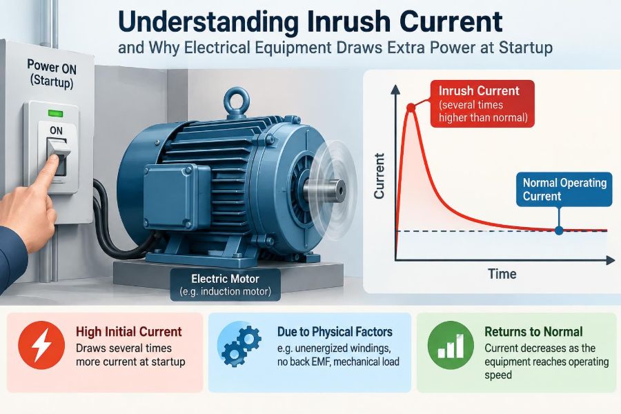
Neither event necessarily means the equipment is faulty. Many electrical loads draw a brief, unusually large current at the instant they are energized. This event is called inrush current.
That short surge can be easy to overlook because it often lasts only milliseconds or a few cycles of the AC supply. Yet it influences conductor sizing, breaker selection, voltage stability, contactor life, power-supply design, and the reliability of whole installations.
Understanding what causes startup current makes several puzzling electrical behaviors much easier to diagnose. It also helps distinguish a normal transient from a condition that deserves attention.
⚡ What Inrush Current Actually Means
Inrush current is the high input current drawn immediately after a device is switched on or connected to a source. It is usually far above the current drawn during normal steady operation, but it is temporary.
The word inrush describes current flowing rapidly into something that must establish a new electrical or magnetic state. A capacitor needs to charge, a magnetic core needs to develop flux, and a motor needs energy to accelerate its rotating parts.
Startup current is sometimes used as a broader term. Inrush specifically emphasizes the initial transient, while a motor’s high current during acceleration may continue beyond the first instant.
🔌 Steady-State Current Is a Different Condition
A nameplate current rating generally describes expected operation after a machine has started and reached its normal condition. It does not always describe the highest current that can occur when power is first applied.
For example, a power supply serving an electronic device may settle to a modest input current once its internal capacitors are charged. Its first connection to the mains, however, can briefly look almost like a low-resistance path.
Designing only around steady-state current can therefore produce nuisance trips, excessive voltage dip, or overstressed switching components.
🏃 Why a Short Current Pulse Can Still Matter
Duration matters, but a short event is not automatically harmless. Very high peak current can create substantial heating in a small area, strong electromagnetic forces in conductors, and electrical arcing at contacts.
Protective devices also respond according to both current magnitude and time. A carefully coordinated circuit may tolerate a normal startup pulse while still opening quickly for a sustained fault.
The practical question is not simply, “How large is the peak?” It is also, “How long does it last, how often does it occur, and what equipment experiences it?”
🧭 The Main Physical Causes
Most inrush problems fall into a few physical categories. Identifying the category is more useful than treating every startup surge as the same phenomenon.
- Capacitive inrush: charging an initially uncharged capacitor.
- Magnetizing inrush: establishing flux in a transformer or other magnetic device.
- Motor starting current: energizing a stationary motor before it develops back electromotive force.
- Cold-element surge: a resistive element starts with lower resistance when cold.
A real installation can contain more than one. A motor drive, for instance, may first charge a DC bus and later start its motor.
🪣 Capacitors Behave Like Empty Energy Stores
A capacitor stores energy in an electric field. Before energization, an uncharged capacitor has essentially zero volts across it, so the supply attempts to raise its voltage very quickly.
The first current is limited mainly by the source impedance, wiring resistance and inductance, rectifiers, switches, and the capacitor’s equivalent series resistance. These values can be quite small, creating a high current peak.
A useful analogy is connecting an empty tank to a pressurized pipe. The initial flow is greatest; as the tank’s pressure rises toward the supply pressure, the flow falls.
💻 Switch-Mode Power Supplies and DC Bus Charging
Many electronic products contain a bridge rectifier followed by large bulk capacitors. These capacitors smooth the rectified AC voltage and create a DC bus for a switch-mode power supply, variable-frequency drive, UPS, or inverter.
When connected at an unfavorable point on the AC waveform, the capacitors may charge through a brief, sharp pulse. Multiple identical supplies turned on together can make the combined pulse large enough to affect a shared branch circuit.
This is why a rack of servers, LED drivers, or industrial drives can behave differently at startup than their summed running watts suggest.
🧲 Transformer Magnetizing Inrush
A transformer requires a magnetizing current to establish magnetic flux in its core. Under ordinary operation this current is much smaller than the load current, but the first few AC cycles after energization can be very different.
If the switching instant and residual magnetism in the core combine unfavorably, the core can enter saturation. Once saturated, it cannot support proportional increases in magnetic flux, so the winding draws much higher current limited largely by winding and supply impedance.
Transformer inrush is often asymmetric: one half-cycle can be much larger than the other. It may decay over several cycles or longer depending on the transformer and system conditions.
🧠 Residual Flux Makes Transformer Startup Variable
Turning a transformer off does not guarantee that its core returns to zero magnetic flux. Some residual flux remains, and its direction matters when the transformer is switched back on.
That is why the same transformer can show noticeably different inrush waveforms on different energizations. The switching angle of the AC voltage, core design, source stiffness, and previous operating history all contribute.
Because of this variation, a single captured waveform is useful evidence but not a complete description of worst-case behavior.
🔄 Why Motors Draw High Current at Rest
A running motor produces back electromotive force, often called back EMF. This internally generated voltage opposes the applied voltage and limits current as the motor reaches speed.
At standstill, back EMF is absent. The motor’s impedance is then relatively low, so it draws a high current while producing torque and accelerating the rotor and its load.
For an induction motor, this is commonly called locked-rotor current because a prevented rotor would continue to draw a similar high current until protection operated or damage occurred.
🏭 The Mechanical Load Changes Motor Starting Time
A lightly loaded fan can accelerate quickly, allowing its current to fall promptly. A loaded conveyor, compressor, pump, or high-inertia flywheel may take longer to reach operating speed.
Starting current must therefore be considered with the driven equipment, not just the motor rating. A motor that starts normally when uncoupled may struggle when connected to its real mechanical load.
Low supply voltage can worsen the situation. It reduces available starting torque, prolongs acceleration, and can leave the motor in a high-current state for too long.
🔥 Cold Filaments and Heating Elements
Some resistive loads also have a startup surge. Tungsten lamp filaments and many heating elements have lower resistance when cold than when hot.
At switch-on, the lower cold resistance permits extra current. As the element heats, resistance rises and current settles. This is a different mechanism from charging a capacitor, but it can still stress switches and contribute to a supply dip.
Not every resistive device has a dramatic cold-to-hot resistance change, so the material and temperature behavior matter.
📈 Peak Current, RMS Current, and Energy Are Not Interchangeable
A waveform can have a huge peak but contain limited energy because it is extremely brief. Conversely, a lower current lasting seconds can impose more total heating on conductors or windings.
Peak current helps assess contact stress, semiconductor limits, and instantaneous voltage drop. RMS current relates more directly to heating over a defined interval. Energy and time-current behavior matter for fuses and protective coordination.
Using one number without its time basis can lead to poor conclusions. A meter that reports only a slow average may completely miss the event.
📏 How Engineers Describe an Inrush Event
A useful inrush specification states the peak or waveform, duration, repetition rate, supply conditions, and measurement location. For motors, starting current and start duration are often paired with the expected load and voltage.
For capacitor-input equipment, designers may also care about the charge delivered in the first half-cycle and the allowable repetitive surge rating of a bridge rectifier. For transformers, the asymmetry and decay can be significant.
There is no universal “acceptable inrush current” value. Acceptability depends on the device, supply system, protection, and switching hardware.
🔍 Measuring the Transient Correctly
Capturing inrush usually requires an instrument with enough bandwidth and sample rate to see a fast transient. A current probe with an oscilloscope, power-quality analyzer, or appropriately specified recorder is often more informative than a basic clamp meter.
The measurement method must suit the waveform. Some current clamps are designed for AC RMS measurements and may not faithfully record a narrow, high peak or a DC component in an asymmetric transient.
Measurement also introduces safety concerns. Work on energized distribution equipment should be planned and performed only by qualified personnel using appropriately rated instruments and procedures.
🖥️ Reading a Startup Waveform
A capacitor-charging event often appears as narrow pulses around AC voltage peaks. Transformer inrush can show large, uneven half-cycles that gradually reduce. Motor starting current tends to persist over a visibly longer interval as speed rises.
Waveform shape can reveal more than a maximum value. It helps separate normal behavior from faults such as a stalled motor, a shorted rectifier, a damaged capacitor, or a transformer that is being repeatedly re-energized.
Record voltage at the same time when possible. A current trace without source-voltage information can hide a significant voltage sag.
💡 Voltage Dip Is Often the System-Level Problem
All supply paths have impedance: transformers, cables, busbars, terminals, and utility connections resist sudden current changes to some degree. Inrush passing through that impedance produces a temporary voltage drop.
The equipment creating the surge may survive it easily while neighboring equipment does not. Controls can reset, contactors can drop out, lamps can flicker, and sensitive electronics may restart if the voltage falls below their ride-through capability.
A strong source may make the dip barely visible, while a long feeder or small standby generator can make the same load difficult to start.
🧱 Source Impedance Determines How Stiff the Supply Feels
A “stiff” supply has low effective impedance and holds its voltage relatively well under sudden load changes. A “weak” supply has higher impedance, so identical inrush causes a deeper voltage disturbance.
This distinction explains why equipment may start reliably in a large building but cause problems at the end of a long rural feeder or on a generator. It is not necessarily a contradiction in the equipment specifications.
Supply impedance should be evaluated across the actual path, including connectors and protective devices, rather than assumed from the service rating alone.
🛡️ Why Breakers Sometimes Trip at Startup
Circuit breakers are designed to distinguish ordinary temporary overloads from severe faults, but their instantaneous magnetic trip functions can react to high current quickly. An inrush pulse that crosses that threshold can create a nuisance trip.
A fuse also has a time-current characteristic. A short pulse may be tolerated, but repeated pulses can accumulate heating and shorten fuse life even if no single start blows it.
Replacing protection with a larger rating simply to stop trips is unsafe unless conductor ampacity, fault protection, equipment ratings, and coordination have all been assessed.
🧩 Protective Device Curves Must Match the Load
Selection involves more than the breaker ampere rating. Trip-curve characteristics, fuse class, expected inrush magnitude, ambient conditions, and the load’s normal operating current all matter.
Motor circuits commonly use protective arrangements that tolerate a normal start while providing overload protection matched to the motor. Electronic equipment may need a time-delay fuse or another approved approach specified by its manufacturer.
The goal is selective behavior: normal energization succeeds, an overload is addressed appropriately, and a short circuit is interrupted rapidly.
🔩 Contacts, Relays, and Switches Feel the Surge
Mechanical contacts experience more than heat. Closing onto a capacitive load can create a high current pulse, while opening an inductive load can generate an arc as current tries to continue flowing.
Repeated inrush can pit relay contacts, weld contacts together, or reduce the useful life of a small switch. A contact rating for resistive loads does not automatically mean it is suitable for motors, transformers, or capacitive power supplies.
Check the switching category and inrush capability of contactors, relays, solid-state relays, and manual switches rather than relying only on a general current figure.
🌡️ Repetition Rate Changes the Design Problem
An appliance switched on once each day presents a different duty from a conveyor motor cycled many times per hour. Repeated inrush heats components before they fully cool and repeatedly applies mechanical and electrical stress.
In an automated process, frequent starts may justify a soft starter, variable-frequency drive, or a revised operating sequence even when each individual start is technically within equipment limits.
Thermal limits, contact wear, and supply disturbance must be considered over the full operating cycle.
⏱️ Staggering Loads Prevents a Combined Surge
Several loads can each be acceptable alone but problematic when energized simultaneously. This is common after restoration of a supply, when many power supplies charge at once and multiple motors attempt to restart.
A simple sequencing controller can apply power in stages. It might energize control electronics first, wait for DC buses to charge, then start motors one at a time according to process priority.
Staggering does not reduce the inrush of an individual device, but it reduces the peak demand imposed on the shared source.
🧯 Precharge Resistors Control Capacitor Inrush
A precharge circuit inserts resistance in series with a capacitor bank during startup. The resistor limits current while the capacitors charge; after the bus reaches a suitable voltage, a relay or contactor bypasses the resistor.
This approach is common where DC-link capacitors are large enough that direct connection would overstress rectifiers, fuses, or contacts. The resistor and bypass device must both be designed for the expected energy and timing.
A precharge resistor is not intended to remain in circuit during normal high-power operation unless the design specifically provides for that loss and heating.
🌡️ NTC Thermistors Offer a Simpler Trade-Off
An NTC, or negative-temperature-coefficient thermistor, has relatively high resistance when cold and lower resistance after it heats from current flow. Placed in series with an input, it can reduce initial capacitor-charging current with few parts.
Its simplicity comes with limitations. If power is briefly interrupted, the thermistor may still be hot and low-resistance when power returns, providing much less inrush limiting on the next start.
It also dissipates power in normal use and may be unsuitable for high-duty cycling or installations requiring predictable restart behavior.
🎚️ Soft Starters and Variable-Frequency Drives
For many AC motors, a soft starter gradually increases applied voltage to reduce starting current and mechanical shock. Because motor torque changes strongly with voltage, this method must be matched to the load; it is not ideal for every high-torque start.
A variable-frequency drive starts the motor at a lower frequency and controls voltage in relation to frequency. It can provide controlled acceleration, but it introduces its own rectifier/DC-bus inrush and may require input-side measures.
Both methods can improve process behavior, but neither removes the need to evaluate cables, protection, harmonics, bypass arrangements, and maintenance requirements.
🔁 Controlled Transformer Switching
Large transformer installations may use controlled switching equipment that closes poles at selected points on the voltage waveform. The intention is to reduce the chance of driving the core deeply into saturation.
This is specialized equipment, not a general solution for small transformers. Its effectiveness depends on accurate knowledge or estimation of residual flux, breaker timing, and the transformer connection.
For ordinary equipment, proper protective-device selection and realistic allowance for energization current are usually more practical.
🚫 Common Misdiagnoses to Avoid
A startup trip is not automatically normal inrush. Treating it that way can conceal a real fault, especially if behavior has changed or the event lasts longer than expected.
- A motor that does not accelerate may have an excessive mechanical load, phase loss, low voltage, or winding problem.
- A power supply with abnormally high repetitive input current may have failed input components.
- A transformer that hums loudly and draws sustained current may be overexcited or damaged.
- A new trip after an installation change may result from combined loads or altered protection settings.
Compare the observed current, duration, voltage, and equipment condition with design information before choosing a remedy.
🧰 A Practical Troubleshooting Sequence
Start with safe observation: identify exactly when the disturbance occurs, which loads are energized, and whether the event is repeatable. Check for obvious changes such as added equipment, altered wiring, loose terminals, or a changed mechanical load.
- Confirm normal running current and supply voltage.
- Measure startup current and voltage with suitable equipment.
- Determine whether the waveform resembles capacitive, transformer, or motor behavior.
- Review protection ratings and time-current characteristics.
- Assess source impedance and simultaneous loads.
- Apply an engineered remedy, then verify operation under realistic conditions.
Do not defeat protective devices, bypass interlocks, or repeatedly reset a tripping circuit without finding the cause.
📐 Designing for Inrush From the Beginning
Good design begins with a startup profile, not only a normal power calculation. Identify energy-storage components, motor starting method, expected switching frequency, source capacity, protection characteristics, and the sensitivity of nearby loads.
Allow for tolerance and operating variation. Capacitor value, transformer residual flux, temperature, supply voltage, and mechanical load can all shift the observed result.
For larger or safety-critical systems, verify the plan with manufacturer data, calculations, and representative testing. Local electrical rules and equipment instructions still govern installation choices.
📝 Useful Questions for a Design Review
A brief set of questions can expose startup issues before equipment is installed:
- What creates the initial current: capacitors, magnetic cores, motors, cold elements, or a combination?
- What peak and duration should the upstream equipment tolerate?
- Will several loads restart at the same time after a power interruption?
- Can the source maintain voltage for controls and neighboring equipment?
- Are switches, relays, fuses, and breakers rated for this load type?
- What happens during rapid off-on cycling or an unsuccessful motor start?
Answers do not need artificial precision to be useful, but they should be based on actual equipment data where available.
✅ The Core Principle Behind Startup Power
Electrical equipment draws extra power at startup because it is establishing a condition that does not yet exist: stored charge, magnetic flux, rotational speed, or operating temperature. Once that condition is established, the current usually falls to its normal running level.
The effect is not inherently a defect. It becomes an engineering problem when the surge exceeds the capability of the supply path, protective device, switching component, or connected equipment.
The most reliable response is to identify the mechanism, measure the event appropriately, and choose a solution that fits the load and system rather than merely making the symptom disappear.
Inrush current is a normal electrical transient, but successful systems are designed so that normal startup never looks like a fault. ⚡🔧📈