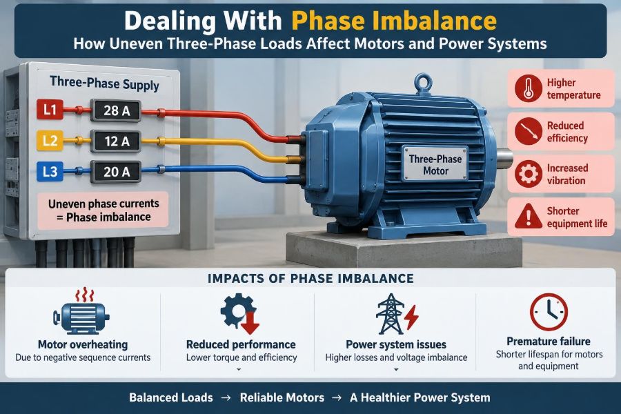

A maintenance technician walks past a motor control center and notices something subtle: one feeder is consistently warmer than the others. The motor is still running, production has not stopped, and no protective device has tripped. Yet the electrical system is telling a story that deserves attention.
Three-phase power is designed to deliver energy smoothly and efficiently. When its three phases share voltage and current evenly, motors develop steady torque, conductors operate predictably, and transformers use their capacity well. Real facilities, however, rarely remain perfectly balanced.
Single-phase lighting, office equipment, welding machines, uneven branch circuits, poor connections, and utility-side conditions can all make one phase work harder than the others. The result may be a modest nuisance, or it may become a source of overheating, motor derating, voltage problems, and unexpected downtime.
Understanding phase imbalance helps engineers and technicians distinguish a harmless measurement variation from a condition that needs correction. The key is to measure carefully, identify whether voltage or current is driving the issue, and address the source rather than merely treating the symptom.
⚙️ What a Balanced Three-Phase System Looks Like
In an ideal three-phase system, the phase voltages have equal magnitude and are separated by 120 electrical degrees. With a balanced load, each phase also carries the same current magnitude, displaced by the appropriate phase angle.
This arrangement produces nearly constant power transfer. A three-phase induction motor therefore receives a rotating magnetic field with uniform strength, rather than a field that repeatedly weakens and strengthens.
Perfect balance is unusual in field measurements. The practical goal is not mathematical perfection; it is keeping deviation small enough that equipment remains within its ratings and operates reliably.
📏 Defining Voltage and Current Imbalance
Voltage imbalance means the three line-to-line or line-to-neutral voltages are unequal. Current imbalance means the phase currents are unequal. They often appear together, but they are not interchangeable and can have different causes.
A common screening calculation is percent voltage imbalance: find the average of the three measured voltages, find the largest deviation from that average, divide by the average, and multiply by 100.
For example, measured line-to-line voltages of 478 V, 480 V, and 482 V average to 480 V. The largest deviation is 2 V, so the imbalance is about 0.42%. Use the method specified by the applicable equipment documentation or standard when compliance or acceptance decisions are involved.
🧭 Why Phase Sequence Is a Different Problem
Phase sequence describes the order in which phase voltages reach their peaks, such as A-B-C rather than A-C-B. Reversing two phases changes the sequence and can reverse a three-phase motor’s rotation.
Imbalance concerns unequal magnitudes or unequal loading. A system can have the correct phase sequence and still be badly unbalanced, or have balanced voltages with the wrong sequence after maintenance.
Both checks belong in commissioning, but they answer different questions. A phase rotation meter checks sequence; voltage and current measurements reveal imbalance.
🧲 Why Motors React So Strongly
An induction motor is particularly sensitive to voltage imbalance because unequal phase voltages create a component of voltage that rotates opposite to the normal magnetic field. This is commonly described using symmetrical components as a negative-sequence voltage.
The negative-sequence field induces currents in the rotor at a high relative frequency. Those currents add heating while producing braking rather than useful motoring torque. Even a voltage imbalance that looks small on a meter can lead to a noticeably larger current imbalance.
That amplification is why motor terminals deserve special attention. A motor can be supplied from a panel that appears acceptable while a poor connection or undersized conductor causes a local imbalance at the motor.
🔥 Rotor Heating and Reduced Motor Life
Extra rotor current raises losses in rotor bars, end rings, and related components. Stator winding current may also become uneven, making one winding phase run hotter than the others.
Insulation aging is strongly related to operating temperature. Persistent excess heat can shorten winding life, weaken varnish systems, and make a motor less tolerant of future overloads or harsh ambient conditions.
Thermal protection is valuable, but it is not a substitute for correcting supply quality. A protector may trip only after harmful heating has already occurred, especially if the imbalance varies with the production cycle.
📉 Torque, Speed, and Starting Consequences
A voltage-unbalanced motor has less usable torque margin. Under a light load, it may continue operating with little obvious change. Under a heavily loaded conveyor, pump, compressor, or fan, the same motor may draw excessive current or fail to accelerate properly.
Starting is demanding because the motor initially draws high current. Voltage drops that are minor at steady state can become much worse during starting, particularly on long feeders or weak supply systems.
Symptoms may include slow acceleration, repeated overload trips, contactor chatter, or a motor that sounds unusually rough as it comes up to speed. Mechanical binding can create similar symptoms, so electrical measurements should be paired with mechanical checks.
🌡️ Uneven Heating Is a Useful Clue
Thermal imaging can reveal unequal temperatures at terminals, fuse clips, disconnects, breakers, cable lugs, and motor junction boxes. A hot phase is not automatic proof of phase imbalance, but it is a strong reason to investigate.
A localized hot spot often points to high-resistance contact: loose hardware, oxidation, damaged strands, an incorrectly torqued lug, or a worn fuse holder. In that case, the voltage may be reasonably balanced upstream but drop significantly across the faulty connection under load.
Compare like-for-like components under similar load conditions. Temperature differences are more meaningful than a single absolute temperature reading because ambient conditions and enclosure ventilation affect every component.
🏭 How Single-Phase Loads Create Current Imbalance
Commercial and industrial buildings often distribute many line-to-neutral loads across a three-phase, four-wire system. Lighting circuits, receptacles, small appliances, control power, and electronic equipment may accumulate unevenly over time.
Imagine a workshop where extra receptacles and portable heaters have repeatedly been added to phase A because that panel space was convenient. The feeder may now carry much higher current on phase A even though the main service was originally balanced.
This is primarily a load-allocation issue. Moving selected branch circuits to less-loaded phases can reduce conductor heating and free usable capacity without changing the total building load.
🏗️ Large Single-Phase Equipment Can Shift the Balance Quickly
Some loads are intermittent but substantial: resistance heaters, welders, single-phase HVAC equipment, temporary construction tools, and certain charging equipment. Their operation can produce phase-current swings that a one-time spot measurement misses.
A data logger or power-quality analyzer is useful when operations change throughout the day. It can show whether the imbalance is constant, tied to a shift, or triggered by a particular machine cycle.
Intermittent load does not automatically mean unacceptable load. The engineering question is whether conductors, transformers, voltage regulation, and connected equipment can tolerate the resulting duty cycle.
🔌 Loose Connections and High-Resistance Faults
A loose or corroded connection creates resistance in series with the load. As current rises, the voltage drop across that resistance rises too, leaving less voltage for the equipment on that phase.
This condition can escalate: resistance produces heat, heat can further degrade contact surfaces, and degradation increases resistance. The visible symptom may be one overloaded-looking phase even when the downstream load itself is balanced.
De-energized inspection, cleaning where appropriate, correct conductor preparation, and tightening to the manufacturer’s specified torque are essential. Never retorque energized equipment, and do not assume a tighter connection is always safer; overtightening can damage threads, lugs, or conductors.
⚡ Utility-Side Voltage Unbalance
Not every imbalance originates inside the facility. Unequal loading on a utility distribution circuit, transformer-bank issues, regulator operation, or a poor upstream connection can cause unbalanced service voltage.
A practical way to narrow the source is to measure at several points: the service entrance, the distribution equipment, the motor controller, and the motor terminals. If the imbalance is present at the service with facility loads disconnected or reduced, coordination with the utility may be needed.
Only qualified personnel should perform these measurements, particularly in energized switchgear. Available fault energy and approach boundaries may make a measurement plan more consequential than the meter selection itself.
🔺 Delta and Wye Systems Behave Differently
In a wye system with a neutral, uneven line-to-neutral loads create unequal phase currents. The neutral carries the vector sum of those currents, rather than their simple arithmetic sum under ordinary sinusoidal conditions.
In a three-wire delta system, there is no neutral conductor for ordinary line-to-neutral loads. The load arrangement and measurement references differ, but phase voltage and line current can still be unbalanced.
Transformer connections also influence how certain unbalanced currents are reflected upstream. The details matter in system design, so unfamiliar transformer arrangements should be analyzed with the manufacturer’s information and a proper one-line diagram rather than guessed from conductor colors.
🌀 The Special Case of Open-Delta Operation
An open-delta transformer bank can provide three-phase service using two transformer units, often as a temporary arrangement after one unit is removed from a closed delta bank. It has less capacity than the original three-unit configuration and can be more sensitive to load distribution.
It is not simply a normal delta bank with one transformer missing from the maintenance plan. Loading, voltage regulation, and transformer heating must be evaluated for the actual configuration.
When a facility experiences recurring imbalance after a transformer outage or reconfiguration, verify the bank arrangement before relocating loads. The limitation may be system capacity rather than a poorly chosen branch circuit.
🖥️ Nonlinear Loads Add a Separate Complication
Variable-frequency drives, switch-mode power supplies, LED drivers, UPS systems, and other electronic loads do not draw perfectly sinusoidal current. They produce harmonic currents in addition to the fundamental-frequency current.
Harmonics can increase RMS current, transformer heating, and neutral loading in four-wire systems. Triplen harmonics—odd multiples of the third harmonic—can add in the neutral when they are in phase across the three phases.
Harmonic distortion and phase imbalance are related only in some cases. A system may be balanced but harmonic-rich, unbalanced with low distortion, or affected by both. Measure the quantities separately before choosing filters, conductor changes, or load relocation.
📊 Measuring the Right Electrical Quantities
A basic survey should include all three line-to-line voltages, all three phase currents, and the load condition at the time of measurement. For wye systems, line-to-neutral voltages and neutral current may also be informative.
Record true RMS values with instruments suitable for the waveform and environment. For diagnostic work, useful additional data include real power, reactive power, power factor, demand profile, harmonics, frequency, and voltage events.
- Measure at the same point in the system for all phases.
- Use the same operating state when comparing readings.
- Verify meter leads and current-probe orientation.
- Write down equipment status, not just numerical results.
A current clamp placed on the wrong conductor, or readings collected during different machine states, can create a convincing but false imbalance diagnosis.
🧮 Reading a Current-Imbalance Example
Consider a hypothetical three-phase feeder with currents of 82 A, 78 A, and 61 A while serving a mixed group of loads. The average is about 73.7 A, and the largest deviation is about 12.7 A. That suggests a material current imbalance worth investigating.
The next question is not immediately whether to replace the feeder. Check the phase voltages under the same load. If voltages are nearly equal, the unequal currents may come from uneven single-phase load allocation or a problem within one branch load.
If the phase with abnormal current also has a depressed voltage, inspect connections and trace the voltage drop. The measurement pattern directs the troubleshooting path.
🔍 Separating Supply Problems From Load Problems
A useful diagnostic principle is to compare voltage imbalance at successive locations and to observe what happens as loads are turned on or off. A supply problem tends to remain visible upstream. A downstream problem often appears or worsens after a particular feeder, controller, or load is energized.
For motors, measure voltage at the motor terminals while the motor is running. Measuring only at the switchboard can hide feeder drop, contactor contact wear, fuse issues, or terminal problems.
Lockout, verification of absence of voltage, and safe work practices are required before opening equipment for physical inspection. Troubleshooting does not justify bypassing electrical safety procedures.
🛠️ Rebalancing Branch Circuits
When unequal single-phase loading is the cause, rebalancing means moving selected branch circuits so that their expected demand is distributed more evenly among phases. The best candidates are known, reasonably steady loads with enough circuit flexibility to move safely.
Do not balance by breaker count. Three 20 A breakers may serve loads with entirely different actual demand. Use measured demand, operating schedules, and likely future additions.
After moving circuits, update panel schedules and one-line documentation. An undocumented phase move can confuse future troubleshooting, affect phase-sensitive equipment, and create avoidable maintenance risk.
🔧 Correcting Voltage-Drop Sources
Voltage imbalance caused by a high-resistance path requires repair at the fault location. Typical remedies include replacing damaged lugs or fuse clips, repairing conductors, servicing disconnects, and replacing worn contactors or breakers as appropriate.
Conductor sizing also matters. A long feeder with acceptable average voltage drop may still show poor performance if one phase has a damaged conductor or substantially different connection resistance.
Simply increasing upstream voltage is rarely a responsible fix for a localized voltage-drop fault. It can overvoltage healthy phases while the defective path continues to overheat.
🧰 When Motor Derating Enters the Decision
Motor manufacturers provide guidance on permissible voltage variation and, in some cases, derating when voltage unbalance cannot be eliminated. Derating means reducing the mechanical load the motor is expected to carry so its temperature remains acceptable.
Derating is a conditional engineering decision, not a universal field rule. It depends on the actual motor design, measured terminal voltage imbalance, ambient temperature, service factor, load profile, and cooling conditions.
If a motor is already near full load, do not assume it has enough thermal margin for an unbalanced supply. Consult the motor documentation and a qualified engineer when continued operation is being considered.
🛡️ Protective Devices Have Limits
Overload relays, electronic motor protection, phase-monitoring relays, and drive fault functions can reduce damage risk. Depending on their design, they may detect phase loss, phase reversal, undervoltage, voltage imbalance, current imbalance, or excessive temperature.
Settings matter. Protection set too loose may allow damaging operation; settings set too tightly may trip during normal starting or process transients. Protection should be coordinated with the motor’s nameplate data and the driven load.
A phase-monitoring relay can identify a bad condition, but it cannot distribute loads or repair a corroded termination. Treat protective devices as a safety layer, not as the corrective action.
🚦 Variable-Frequency Drives Change the Picture
A variable-frequency drive rectifies incoming AC and synthesizes a controlled output for the motor. This can isolate the motor from some supply-frequency voltage variations, but it does not make poor input power irrelevant.
Input phase imbalance may raise stress on the drive’s rectifier and DC bus, cause faults, or require input-reactor and supply-system evaluation. On the output side, the drive itself should produce balanced motor voltage when operating normally, but cable, motor, and control issues can still create problems.
Use drive manufacturer limits and diagnostic data. Applying line-side motor rules directly to a drive output, or treating a drive as a universal imbalance cure, can lead to poor decisions.
🏢 Transformer Capacity Is Not Just Total kVA
A transformer may have enough total apparent-power capacity while one phase winding, conductor, or protective device is approaching its limit. Uneven loading reduces how effectively the installation can use its nameplate capacity.
For a building transformer serving many single-phase loads, periodic phase-current surveys are especially valuable after renovations, tenant changes, or large equipment additions. The phase with the highest sustained demand often determines the practical constraint.
Balanced loading also improves voltage regulation because no one phase suffers disproportionate drop from its own current. This benefits sensitive equipment downstream, even if the transformer itself is not overheating.
📡 Monitoring Makes Intermittent Problems Visible
Handheld readings are excellent for immediate checks, but they are snapshots. Permanent meters, portable loggers, and power-quality analyzers can reveal trends that occur at night, during startup, or only when a process runs at full output.
Useful alarms might identify sustained phase-current differences, voltage imbalance beyond a site-defined threshold, excessive neutral current, or repeated undervoltage events. Thresholds should be chosen from equipment limits and the facility’s operating needs, not copied blindly.
Trend data also verifies repairs. If rebalancing circuits reduces peak current on one phase but creates a new peak on another shift, the process has not yet reached a stable solution.
🧯 Common Troubleshooting Mistakes
The most frequent mistake is treating any unequal current as a motor failure. Current follows both the applied voltage and the mechanical load, so the supply, wiring, controller, and driven equipment all deserve consideration.
- Comparing currents without recording voltage at the same time.
- Measuring only at a panel instead of at motor terminals.
- Ignoring neutral current and harmonics in electronic-load areas.
- Moving circuits based on breaker ratings rather than actual demand.
- Using a single momentary reading to diagnose an intermittent condition.
- Assuming a warm connection is normal because the equipment still runs.
A disciplined sequence of measurements is faster than repeated component replacement based on suspicion.
📝 A Practical Investigation Sequence
Start by defining the complaint: motor overheating, overload trips, dimming lights, a hot conductor, or an unusual power-quality alarm. Then collect measurements at a known operating condition before changing anything.
- Verify phase sequence and safely inspect accessible equipment for damage or discoloration.
- Measure three-phase voltage and current at the affected equipment.
- Compare readings upstream and downstream to locate added voltage drop.
- Review load allocation, schedules, and recent equipment changes.
- Inspect and repair confirmed connections or components under proper safety controls.
- Rebalance loads where appropriate, then remeasure and document the result.
If the pattern points upstream, involve the responsible utility or facility power engineer with clear time-stamped data.
👷 Designing for Better Balance From the Start
New installations benefit from spare panel capacity, thoughtful phase assignment, adequate neutral design where nonlinear loads are expected, and accessible test points. These choices make future maintenance less disruptive.
For large motor loads, consider feeder length, starting method, source stiffness, transformer impedance, and the expected simultaneous operation of other loads. A design that works at nominal conditions can still struggle during starts or peak demand.
Documentation is part of the design. Accurate panel schedules, one-line diagrams, circuit identifiers, and records of load changes turn a future imbalance investigation into a manageable engineering task.
📚 Standards, Ratings, and Engineering Judgment
Equipment instructions, local electrical codes, workplace safety rules, and applicable industry standards all shape what is acceptable in a particular installation. Their requirements may differ by jurisdiction, equipment type, and whether the work concerns design, maintenance, or power quality.
General rules of thumb are useful for recognizing a concern, but they do not replace the manufacturer’s allowable-voltage guidance or a system study. This is particularly true for critical motors, medical facilities, data centers, hazardous locations, and systems with high available fault energy.
When conditions are persistent, complex, or safety-critical, engage a qualified electrical engineer or power-quality specialist. The objective is not merely to make readings look equal; it is to ensure reliable operation within equipment limits.
✅ The Core Principle: Find the Cause, Not Just the Unequal Reading
Phase imbalance is a system condition, not a single diagnosis. Unequal readings may come from uneven single-phase loads, poor connections, feeder impedance, transformer configuration, utility supply conditions, harmonics, or an issue in the equipment itself.
Voltage imbalance deserves prompt attention around motors because it can drive disproportionately uneven currents and heating. Current imbalance deserves equally careful interpretation because it may reveal overloaded phase conductors, poorly allocated loads, or a developing connection fault.
The most reliable response is straightforward: measure under real load, compare locations, inspect safely, correct the identified cause, and verify the result over time.
Balanced three-phase power is not about chasing perfectly identical numbers; it is about keeping voltage, current, equipment temperature, and loading within conditions that the whole system can safely sustain. ⚡🔧📈