
A building can look perfectly ordinary while a carefully coordinated electrical system works behind every wall, ceiling, and equipment room. Lights turn on, elevators move, servers stay online, and motors start because power has been transformed, routed, protected, and controlled before it reaches the point of use.
When something fails, the visible symptom may be small: one dark corridor, a tripped breaker, or a machine that will not start. The underlying cause, however, may lie much farther upstream—in the load calculation, transformer selection, feeder sizing, protective coordination, or even a loose termination.
Understanding the path from transformer to final load makes electrical drawings less mysterious. It also helps students connect circuit theory to real installations and helps working professionals diagnose problems, communicate design intent, and recognize where safety boundaries matter.
An electrical distribution system is not merely a collection of wires and panels. It is a layered system that must deliver usable voltage, limit fault energy, isolate problems, accommodate change, and do so under normal and abnormal operating conditions.
⚡ The Big Picture: A Controlled Path for Power
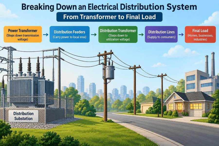
Electrical distribution is the portion of the power system that carries electricity from a source—often a utility service or on-site generation—to equipment that consumes it. Its basic path is easy to state: source, transformer where needed, switchgear, feeders, distribution panels, branch circuits, and loads.
In practice, every stage has a separate job. Conductors carry current; transformers change voltage; overcurrent protective devices interrupt dangerous current; and disconnects provide a visible or operable means to isolate equipment.
Think of the system as a transportation network. High-capacity routes move power efficiently over longer distances, while smaller routes deliver it to individual destinations. The comparison is useful, but electricity adds a critical requirement: the network must respond safely when a short circuit or overload occurs.
🏭 Where the Electrical Supply Begins
For many facilities, power enters from a utility distribution network at either low voltage or medium voltage. Larger campuses, industrial plants, and tall buildings commonly receive power at a higher voltage and transform it on site; smaller premises may receive utility low-voltage service directly.
The service entrance is the transition between the utility supply and the customer’s installation. Equipment at this point may include metering, a service disconnect, switchgear, surge protection, and grounding connections, depending on the supply arrangement and local requirements.
The exact ownership boundary varies by utility and jurisdiction. Designers must not assume that a familiar arrangement applies everywhere; utility rules, electrical codes, and the available fault current at the service all influence the equipment selected.
🔄 Why Transformers Appear in the System
A transformer transfers alternating-current energy magnetically between windings and changes the voltage level according to its turns ratio. It does not create power; ideally, it trades voltage for current while keeping apparent power nearly balanced apart from losses.
Higher voltage is useful upstream because a given amount of power can be transmitted with lower current. Lower current reduces conductor losses and can allow more practical conductor sizes. Near the loads, the voltage is stepped down to levels suitable for utilization equipment.
For example, a facility might use a medium-voltage-to-low-voltage transformer to supply a main low-voltage switchboard. Smaller transformers may then serve special voltages, isolated systems, control circuits, or local equipment.
🧲 Reading the Transformer Nameplate
A transformer nameplate provides the design facts needed for installation and coordination. Common entries include rated power, primary and secondary voltage, frequency, phase arrangement, temperature rise, impedance, tap information, and cooling method.
Transformer impedance, often shown as a percentage, strongly affects the prospective short-circuit current on the secondary side. A lower-impedance transformer generally permits higher fault current, which can demand equipment with higher interrupting and withstand ratings.
Ratings must be interpreted as a whole. A transformer may have enough kVA capacity but still be unsuitable if its voltage, vector arrangement, impedance, enclosure type, or environmental rating does not match the installation.
🌐 Single-Phase and Three-Phase Distribution
Single-phase systems are common for small loads and many residential applications. Three-phase systems are widely used in commercial and industrial facilities because they deliver power smoothly to motors and distribute large loads efficiently.
In a balanced three-phase load, each phase carries similar current. Real buildings are rarely perfectly balanced: lighting, receptacles, electronic power supplies, and single-phase equipment may load phases unequally.
Phase balancing is not simply neat drafting. It helps limit voltage imbalance, avoids overloading one phase or neutral conductor, and improves the operating conditions seen by three-phase motors. Balance should be checked during design and revisited when major loads are added.
🧭 Choosing a Grounding Arrangement
Grounding and bonding are related but different. Grounding connects part of the electrical system to earth or an intentionally grounded reference. Bonding connects conductive parts together so they remain at substantially the same potential and provide an effective fault-current path.
Common system arrangements include solidly grounded, impedance-grounded, and ungrounded systems. The right choice depends on the voltage, continuity needs, fault-detection strategy, and applicable rules. An industrial process may value continued operation during a first ground fault, while another installation may prioritize straightforward fault clearing.
A grounding conductor is not a normal load-current return path in a properly operating system. If protective metalwork carries routine current, that is a warning sign requiring investigation.
🧰 Main Switchgear: The System’s First Major Control Point
After transformation or service entry, power commonly reaches main switchgear, switchboards, or a main distribution panel. These assemblies house busbars, breakers or switches, metering, protective functions, and outgoing feeder connections.
Terminology differs by region and equipment type, but the functional questions remain the same: What is the continuous current rating? What fault current can the equipment withstand and interrupt? Which circuits leave the assembly, and what protection do they have?
Main equipment is also a key operational boundary. It may provide the place to disconnect a whole building section, transfer between sources, or monitor overall demand and power quality.
🛡️ The Purpose of Overcurrent Protection
Fuses and circuit breakers protect conductors and equipment from excessive current. Overcurrent usually falls into two broad categories: overloads, which are currents above normal operating level over time, and short circuits or ground faults, which can produce very high current rapidly.
Protection is selected so the conductor can carry intended load current while the protective device opens before damaging heating occurs under fault or overload conditions. This is why a larger breaker is not a fix for repeated tripping; it can defeat the conductor’s protection if applied incorrectly.
A breaker may offer thermal-magnetic, electronic, or other trip characteristics. The details affect its response, adjustment range, diagnostics, and suitability for coordination with upstream and downstream devices.
🎯 Selective Coordination and Fault Isolation
When a fault occurs on a branch circuit, the preferred outcome is usually for the branch protective device to operate while upstream service remains available. This behavior is called selective coordination.
Achieving it requires more than arranging breaker ratings from small to large. Time-current curves, instantaneous settings, fuse characteristics, available fault current, and device tolerances all matter. At high fault current, a downstream device may enter an instantaneous region where timing margins become narrow.
Perfect coordination is not always technically achievable or economically justified across every part of a system. Critical facilities may demand more analysis and robust coordination than a simple, low-risk installation, but the objective is always to limit the outage to the smallest practical area.
📏 Feeder Circuits: Moving Power Between Assemblies
A feeder supplies power from one distribution point to another, such as from a main switchboard to a floor panelboard, motor control center, or remote distribution board. It is generally larger and carries more aggregate load than an individual branch circuit.
Feeder design considers ampacity, voltage drop, installation method, ambient temperature, grouping with other conductors, terminal ratings, short-circuit duty, and the expected load profile. A conductor that looks adequate from a simple current calculation can be inadequate after correction factors are applied.
Feeder routes also affect maintainability. Long, congested pathways can make pulling, inspection, expansion, and heat dissipation more difficult. Physical layout is part of electrical design, not an afterthought.
📉 Voltage Drop Is a Performance Issue
Voltage drop occurs because conductors have impedance. As current flows, some voltage is lost along the path, leaving less voltage at the load. Excessive drop can cause dim lighting, poor motor starting, control problems, and electronic equipment behavior that appears intermittent.
Resistance is often the dominant factor in short low-voltage runs, while reactance becomes more significant in some larger or longer alternating-current systems. Conductor size, length, material, arrangement, power factor, and current all influence the result.
Voltage-drop targets are typically design recommendations or project criteria rather than a single universal number. The practical question is whether the equipment will receive acceptable voltage under expected operating and starting conditions.
🧮 Load Calculations Are Not a Sum of Nameplates
A connected load is the total rating of all equipment that could be connected. The demand load is the amount expected to operate simultaneously. Treating both as identical can lead either to oversized, costly infrastructure or to a system that cannot support realistic operation.
Load calculations account for diversity: not every receptacle, heater, motor, and lighting circuit runs at full rating at the same moment. Yet diversity must be applied with engineering judgment. A production process with synchronized equipment can have a very different demand pattern from an office floor.
Future capacity deserves explicit discussion. Leaving reasonable space, bus capacity, and routing provision may be wise; blindly oversizing every component is not automatically good engineering.
🚪 Panelboards and Distribution Boards
Panelboards divide feeder power into smaller circuits and place protection closer to the loads. They are often arranged by area or function: a lighting panel for a floor, a receptacle panel for offices, or a dedicated panel for mechanical equipment.
Clear circuit directories are a practical safety feature. A directory should identify what each circuit actually serves, not merely say “lights” or “spares.” Accurate labeling reduces the chance that maintenance personnel isolate the wrong circuit.
Panel capacity has several dimensions: number of poles, bus rating, main-device rating where present, short-circuit rating, and available physical space. Empty breaker spaces alone do not prove that additional load can be added safely.
🔌 Branch Circuits and the Final Distribution Step
A branch circuit extends from the final overcurrent protective device to outlets, luminaires, fixed equipment, or another final utilization point. It is the part of the system users encounter most directly, though much of it remains hidden inside walls and conduits.
Branch circuits are sized for both the load and the installation conditions. Continuous operation, motor duty, conductor temperature limitations, termination ratings, and the type of load can change the required conductor and breaker selection.
At this stage, good design avoids mixing unrelated critical functions indiscriminately. A fault in a convenience receptacle should not unnecessarily remove lighting or controls needed for safe operation.
💡 Lighting Loads Behave Differently Than They Once Did
Modern LED drivers use electronic power conversion. They can be efficient, but their input current may contain harmonics and may not behave like a simple resistive lamp load. Large lighting upgrades can therefore change neutral loading and power-quality conditions.
Inrush current is another consideration. A group of electronic drivers may draw a brief high current when energized, potentially causing nuisance tripping if circuit design and breaker characteristics are mismatched.
Lighting controls add another layer. Occupancy sensors, dimmers, contactors, and building automation interfaces need compatible wiring and commissioning. A luminaire can be electrically energized yet fail to operate as intended because the control path is wrong.
⚙️ Motors Demand Special Attention
Motors can draw substantially higher current during starting than during steady running. The starting method—direct-on-line, soft starter, variable-frequency drive, or another approach—changes the current profile and the impact on the supply.
A motor branch circuit commonly needs short-circuit and ground-fault protection, a controller, and overload protection. These functions should not be casually treated as interchangeable. A breaker may protect against short circuit, while an overload relay or drive function protects the motor from sustained overload.
Motor starting also interacts with voltage drop. If the supply voltage sags too far during start, the motor may accelerate slowly or fail to reach speed, prolonging the high-current condition.
💻 Electronic Loads and Power Quality
Computers, variable-speed drives, rectifiers, chargers, and LED drivers often use nonlinear input circuits. Their current waveform can differ from the voltage waveform, creating harmonic currents that may heat conductors and transformers or distort voltage under certain conditions.
Power quality also includes sags, swells, transients, interruptions, flicker, and phase imbalance. The symptom may be a rebooting controller, unexplained drive fault, or communication error rather than an obvious electrical failure.
Measurement is better than assumption. A suitable power-quality survey can reveal when events occur and whether they correlate with switching, motor starting, utility disturbances, or a particular load.
🌩️ Surge Protection and Transient Control
Surges are short-duration overvoltages that can arise from lightning effects, utility switching, or switching of inductive loads inside a facility. They may not trip a breaker, yet repeated or severe events can stress electronic equipment.
Surge protective devices are commonly installed at service and distribution locations, with additional local protection for sensitive equipment where justified. Their effectiveness depends on correct installation, including short connection paths and an effective bonding system.
Surge protection is one layer of resilience, not a substitute for grounding, bonding, correct circuit design, or equipment rated for its environment. Sensitive systems may also need isolation, filtering, or ride-through capability.
🔋 Emergency Sources Change the Distribution Strategy
Generators, batteries, uninterruptible power supplies, and other alternate sources can maintain selected loads during a utility outage. They add complexity because the system must safely transfer sources, manage neutral and grounding behavior, and prevent unintended backfeed.
Critical loads are usually separated from ordinary loads so the emergency source is not burdened by every circuit in the building. The chosen loads may include life-safety functions, controls, communications, data equipment, or process systems, depending on the facility.
Transfer equipment must be selected and maintained for the intended source arrangement. Source switching is not merely a convenience feature; it changes fault paths and operating states that must be understood in the design.
🧩 Segregating Critical, Normal, and Sensitive Loads
A thoughtful distribution architecture groups loads by operational consequence. A laboratory freezer, fire-related system, general office receptacle, and decorative lighting installation should not automatically receive the same level of continuity or monitoring.
Segregation can simplify maintenance as well. If normal loads are on distinct panels or feeders, planned work can occur with less disruption to critical operations. It can also help prevent a nonessential load from consuming emergency-source capacity.
The trade-off is cost and complexity. More panels, feeders, transfer paths, and monitoring points create more equipment to install and maintain, so the architecture should reflect actual risk rather than a desire to make every circuit “critical.”
🧯 Arc Flash and Electrical Safety Boundaries
An arc flash is a hazardous release of energy caused by an electrical arc. It can occur when an arc is sustained through air or across conductive material, producing intense heat, pressure, light, and molten metal.
Risk depends on factors including available fault current, clearing time, equipment configuration, and working distance. Reducing available fault current is not always practical, but faster protective clearing and thoughtful equipment design can reduce incident energy in some cases.
Only trained and authorized people should perform energized electrical work when it is justified and permitted by the governing safety program. De-energizing, verifying absence of voltage with appropriate procedures, and establishing safe work conditions are foundational controls—not optional administrative steps.
🔧 Disconnects Make Equipment Serviceable
A disconnecting means allows equipment to be isolated for maintenance, inspection, or replacement. It may be a local safety switch, a breaker with suitable function, or another approved device positioned where workers can use it safely.
Local isolation matters because equipment is often far from the panel that supplies it. A technician servicing a fan, pump, or machine needs confidence that the circuit cannot be inadvertently re-energized while work is in progress.
Lockout/tagout procedures add control over the human side of isolation. Opening a disconnect alone is not enough when another person could close it or when multiple energy sources are present.
🧱 Physical Installation Affects Electrical Reliability
Conduit fill, bend radius, cable support, enclosure access, ventilation, corrosion exposure, vibration, and water ingress all influence system reliability. Electrical calculations may be correct on paper while the installed system still has poor service life.
Terminations deserve special attention. Loose or improperly torqued connections can develop resistance, heat under load, and eventually damage insulation or equipment. Conversely, excessive torque can harm conductors or terminals.
Installation instructions and approved torque values are part of the engineering chain from design to commissioning. Documenting critical connections and inspection results can make future troubleshooting far more efficient.
🌡️ Heat Is a Clue, Not Just a Byproduct
All loaded electrical equipment produces some heat, but abnormal heating often indicates a problem: overload, poor connection, harmonic current, blocked ventilation, failed cooling, or deteriorating contact surfaces.
Infrared thermography can help identify temperature differences while equipment is operating, but its findings need context. A warm component may be carrying a higher legitimate load, while a seemingly modest temperature can still be significant if compared with similar components under the same conditions.
Thermal inspection is most useful as part of a maintenance program that includes load measurements, visual inspection, cleaning, torque verification where appropriate, and follow-up on trends.
📊 Metering Turns Distribution Into Observable Data
Metering can show voltage, current, demand, energy use, power factor, harmonics, and event history at selected points in a system. At the main service, it provides a broad view; at feeders and panels, it can reveal where loads are concentrated.
Submetering is especially useful where different tenants, departments, processes, or equipment groups need separate visibility. It can identify an unexpected operating schedule or establish whether a claimed load increase is real.
More data is not automatically better. Meter locations, communications reliability, timestamp accuracy, alarm thresholds, and responsibility for reviewing alarms should be defined before a monitoring system is relied upon.
🗺️ Drawings and Labels Preserve System Knowledge
Single-line diagrams show the major electrical path using simplified symbols: sources, transformers, bus sections, breakers, feeders, and major loads. They are essential for understanding topology without tracing every individual conductor.
Schedules, panel directories, equipment labels, settings records, and as-built drawings add the detail that a single-line cannot carry. During an emergency or modification, outdated documentation can become a serious operational risk.
Good records reflect the installation that exists now, not merely the installation originally designed. Every significant modification should trigger review of labels, drawings, protection settings, capacity, and fault-duty implications.
🧪 Commissioning Verifies More Than “It Turns On”
Commissioning checks whether the installed distribution system performs as intended. Activities may include visual inspection, continuity checks, insulation testing where appropriate, phasing verification, torque verification, functional operation, protective-device testing, and review of settings.
Testing must follow equipment instructions and qualified procedures. Some tests can damage sensitive electronics or give misleading results if performed on connected equipment without proper isolation.
Functional testing should include realistic operating sequences when possible: transfer to an alternate source, motor starts, alarm response, control operation, and restoration after a simulated outage. A system that energizes successfully may still fail during a transition.
🚫 Common Design and Maintenance Mistakes
Many distribution failures are traceable to ordinary oversights rather than exotic faults. Typical examples include:
- Adding loads without checking feeder, panel, transformer, and fault-duty limits.
- Replacing a tripping protective device with a larger rating instead of finding the cause.
- Ignoring a hot termination because equipment still operates.
- Leaving circuit directories inaccurate after renovations.
- Changing breaker settings without a documented coordination and safety review.
- Assuming a spare breaker space means spare electrical capacity.
Each error weakens a different layer of protection or understanding. The remedy is disciplined change management: assess, document, test, and update before the next modification obscures the original intent.
🧠 A Practical Troubleshooting Path
When a final load does not operate, start with symptoms and move systematically upstream rather than guessing. Confirm the equipment’s normal behavior, check its local controls and disconnect, then verify voltage and protection status using safe, qualified methods.
For a hypothetical failed pump, the cause could be a local overload trip, a control interlock, a failed drive, an open branch breaker, a feeder issue, or loss of supply farther upstream. The correct test sequence narrows possibilities without creating new hazards.
- Define what changed and which loads are affected.
- Use drawings and labels to identify the intended supply path.
- Check protective devices and indications without defeating safety features.
- Measure only with appropriate instruments, ratings, and qualifications.
- Correct the cause, then verify normal operation and update records if needed.
🏗️ Designing for Expansion Without Waste
Distribution systems often outlive their original occupancy and equipment mix. Expansion planning may include spare feeder capacity, accessible raceway routes, physical space for future equipment, and a bus rating that supports realistic growth.
Flexibility must be targeted. A data center, healthcare space, manufacturing line, and small retail unit have different growth patterns, outage tolerances, and power-density expectations. The best allowance is based on foreseeable scenarios, not a generic multiplier.
Future changes should also consider short-circuit levels and protection coordination. Adding a transformer, generator, or parallel source can alter fault current enough to affect equipment ratings and arc-flash assessments.
✅ The Core Principle: Deliver, Protect, Isolate, Verify
From transformer to final load, every layer of distribution has four recurring purposes: deliver power at usable voltage, protect conductors and equipment, isolate faults or maintenance work, and verify performance through testing and monitoring.
A strong system is not defined only by its ability to carry normal load. It must handle starting current, nonlinear loads, voltage variation, faults, maintenance activities, source transfers, and future modifications with predictable behavior.
For students, this framework turns a one-line diagram into a logical story. For professionals, it provides a disciplined way to review designs and investigate failures: follow the energy path, identify each protective layer, and never separate electrical performance from electrical safety.
An electrical distribution system succeeds when power reaches the final load reliably while faults, changes, and human work are managed deliberately at every stage. ⚡🔧🏢