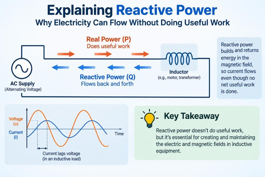

A factory motor is running, a transformer is energized, and the utility meter shows current flowing through the service entrance. Yet not all of that current is being converted into heat, motion, light, or any other useful output.
This can seem counterintuitive. We usually picture electricity as something that travels from a source to a load, does work, and is gone. In alternating-current systems, part of the energy can instead move into a device’s electric or magnetic field and then return to the source a fraction of a cycle later.
That back-and-forth exchange is associated with reactive power. It does not directly deliver net useful energy to the load, but it can still occupy equipment capacity, raise current, increase losses, and affect voltage control.
Understanding reactive power turns power factor from a mysterious number on a utility bill into a practical engineering idea. It also explains why capacitors, synchronous machines, and modern inverters are so valuable to electrical networks.
⚡ Start with the three kinds of AC power
In sinusoidal AC systems, power is commonly separated into three related quantities. Each describes a different aspect of what voltage and current are doing.
| Quantity | Symbol and unit | Meaning |
|---|---|---|
| Active power | P, watts (W) | Average power converted into useful output or losses |
| Reactive power | Q, volt-amperes reactive (var) | Power exchanged with electric or magnetic fields |
| Apparent power | S, volt-amperes (VA) | Combined voltage-current loading seen by equipment |
Active power is the part that heats a resistance, turns a shaft, or supplies an electronic load. Reactive power supports fields needed by many devices. Apparent power reflects the total RMS voltage and RMS current a cable, transformer, switchgear assembly, or generator must carry.
🔌 Why alternating current creates the issue
With a DC resistor, voltage and current are steady and energy flows in one direction: source to resistor. AC voltage and current continually reverse direction, usually 50 or 60 times each second.
Some components store energy temporarily. An inductor stores it in a magnetic field; a capacitor stores it in an electric field. During part of each cycle they take energy from the supply, and during another part they return energy. The average exchanged energy over a complete cycle can be zero while current remains substantial.
🧲 Inductors store energy in magnetic fields
An inductor resists changes in current. In an ideal inductive circuit, current lags voltage by 90 degrees. The source first supplies energy to build the magnetic field, then the collapsing field sends energy back toward the source.
Real inductive equipment is not ideal. A motor winding has resistance, transformers have core loss, and magnetic circuits have imperfections. Consequently, an induction motor consumes both active power and reactive power at the same time.
🔋 Capacitors store energy in electric fields
A capacitor resists changes in voltage. In an ideal capacitive circuit, current leads voltage by 90 degrees. It takes energy to charge the capacitor’s electric field and returns that energy as the field discharges.
This behavior makes capacitors particularly useful in systems dominated by inductive loads. A properly applied capacitor can supply reactive power locally, reducing the amount that must travel from the upstream network. It does not create active energy or make a motor mechanically more efficient by itself.
🌊 A useful picture: power flowing back and forth
Imagine a harbor basin connected to the sea. The tide moves water in and out through the channel, even if the average amount of water in the basin does not change. The channel must still accommodate the flow.
Reactive power behaves similarly: energy oscillates between source and field. The analogy has limits—electrical systems have phase angles, impedance, and network interactions—but it captures the key point: zero net energy transfer does not mean zero current.
📐 Phase angle connects voltage and current
For clean sinusoidal waveforms, the angle between voltage and current is written as φ. If current aligns with voltage, φ is zero. If current lags, the load is inductive; if it leads, the load is capacitive.
The fundamental relationships are:
P = VI cos φ
Q = VI sin φ
S = VI
Here, V and I are RMS voltage and current. These expressions apply directly to a single-phase sinusoidal circuit. Three-phase calculations use corresponding line-voltage and line-current forms, with a factor of √3 for balanced systems.
📊 The power triangle makes the relationship visible
Engineers often draw active power horizontally, reactive power vertically, and apparent power as the hypotenuse. This is the power triangle.
S² = P² + Q²Its angle is φ, and power factor is cos φ. A larger reactive component makes apparent power larger for the same active power. In practical terms, the system needs more current to deliver the same number of useful watts.
🏭 Why motors need reactive power
Induction motors are among the most familiar reactive-power loads. Their stator windings establish a rotating magnetic field, and the field is essential to producing torque. Establishing that field requires magnetizing current.
At light mechanical load, a motor’s active-power demand falls, but much of its magnetizing requirement remains. This is one reason lightly loaded motors can have poor power factor. Choosing a motor far larger than its actual duty can therefore create both capital and electrical-performance penalties.
🔄 Transformers also draw current at no load
A transformer can draw current even when its secondary is open. This excitation current establishes magnetic flux in the core and supplies core losses.
Although no-load current is usually much smaller than rated load current, it is often significantly reactive. In facilities with many lightly loaded transformers, these demands can contribute to the overall reactive-power profile, especially outside peak production hours.
💡 Other common sources of reactive demand
Motors and transformers are not the only causes. Reactive behavior appears wherever inductance or capacitance is significant.
- Welding equipment and magnetic ballasts can be inductive.
- Long cables and underground cable networks contribute capacitance.
- Transmission lines have both inductive series behavior and capacitive shunt behavior.
- Filters, converters, and electronic equipment may have more complex reactive and harmonic behavior.
The net result at a particular electrical bus depends on all connected devices, operating conditions, and network configuration.
🧮 Apparent power determines equipment ratings
A transformer nameplate is commonly expressed in kVA or MVA, not only kW. Its windings and cooling system respond strongly to current, while insulation and core design are tied to voltage. Together, voltage and current determine apparent-power capability.
A generator, UPS, inverter, feeder, and switchgear lineup also have current-related limits. If reactive power increases while useful kW output stays fixed, apparent power rises and available capacity for additional active load can shrink.
🔥 Extra current creates real losses
Reactive power is not “free” merely because it performs no net useful work at the load. When it must travel through resistive conductors, the associated current produces I²R losses.
For a given real-power delivery, lower power factor means higher current. Higher current can cause more heating in cables and transformer windings, greater voltage drop, and less spare capacity. These effects are why reactive-power management is an operational issue rather than an accounting curiosity.
📉 Power factor measures the proportion doing work
For sinusoidal voltage and current, power factor is the ratio of active power to apparent power:
Power factor = P / S = cos φA power factor near 1 means most of the apparent power corresponds to active power. A lower value means a larger share of current is associated with reactive exchange. The terms lagging and leading indicate whether the net reactive effect is inductive or capacitive.
🧾 A simple numerical example
Consider a hypothetical single-phase load receiving 10 kW at 0.80 lagging power factor. Its apparent power is 12.5 kVA, so at a given voltage it requires current corresponding to 12.5 kVA.
If power-factor correction raises the power factor to 0.95 while the active load remains 10 kW, apparent power falls to about 10.5 kVA. The useful output did not change. What changed was the amount of reactive current that the upstream supply, transformer, and feeder had to carry.
🏗️ Why utilities care about reactive power
Utilities must operate networks within voltage and equipment limits. Reactive-power flow has a strong influence on voltage, particularly across inductive transmission and distribution paths.
A large reactive demand far from its source can consume line capacity and contribute to voltage reduction at the receiving end. Conversely, excessive capacitive reactive supply can contribute to high voltage under light-load conditions. Utilities therefore manage both real-power balance and reactive-power balance.
💳 Why some commercial bills include power-factor charges
Billing structures vary by location, customer class, and tariff. Some large customers are charged using peak kVA, assessed for low power factor, or billed separately for reactive energy or demand.
The underlying reason is physical: the utility must size and operate equipment for current and apparent power, not just for metered kWh. Small residential customers are often treated differently because measurement and billing arrangements differ, not because reactive power disappears from their service.
🧰 Capacitor banks provide local reactive support
Capacitor banks are a common correction method for inductive facilities. Installed near a load, motor-control center, or distribution bus, they provide leading reactive power that offsets part of the lagging reactive demand.
That local exchange can reduce upstream current. Banks may be fixed, switched in steps by a controller, or automatically controlled according to power factor, kvar demand, voltage, or a combination of measurements.
⚠️ Overcorrection is not better correction
Adding capacitors until the meter shows a leading power factor can create new problems. Leading power factor may raise voltage, reduce generator margin in some systems, and complicate network operation.
Capacitor output also changes with voltage, while facility load changes through the day. A fixed bank that looks appropriate at full production may overcompensate during an idle shift. Switched stages are often more suitable where loading varies materially.
🎵 Harmonics change the simple picture
The familiar power triangle assumes sinusoidal voltage and current at one frequency. Nonlinear loads—such as many rectifiers, variable-speed drives, and switched-mode power supplies—can draw non-sinusoidal current containing harmonics.
In those systems, a high displacement power factor at the fundamental frequency does not automatically mean low RMS current or high true power factor. Capacitors can also interact with system inductance and harmonic frequencies. A correction design should therefore consider harmonic measurements or a credible system study where significant nonlinear loads exist.
🛡️ Detuned banks and filters reduce resonance risk
Every real power system has inductance. Adding capacitors can create resonant conditions at particular frequencies, potentially amplifying harmonic currents or voltages. The consequences can include capacitor overheating, fuse operation, nuisance trips, and distorted voltage.
Where harmonic risk is relevant, engineers may use detuned capacitor banks with series reactors, tuned passive filters, or active filtering equipment. The correct choice depends on the system impedance, load spectrum, capacitor size, and operational objectives; it should not be guessed from nameplate kW alone.
🧠 Synchronous machines can generate or absorb vars
A synchronous motor or generator can adjust its reactive-power behavior through field excitation. Depending on its operating point, it can absorb reactive power or supply it to the network while producing mechanical output or real electrical power.
A synchronous machine operated primarily for reactive support is called a synchronous condenser. These machines offer controllable voltage support and can provide other grid-strength characteristics, though they require more maintenance and infrastructure than a simple capacitor bank.
🔋 Inverters are modern reactive-power tools
Solar, battery, and other power-electronic inverters can often control reactive power rapidly within their design limits. They may operate at a specified power factor, follow a voltage-reactive-power characteristic, or receive a utility command.
There is a tradeoff: an inverter has a finite apparent-power rating. When it is producing high real power, less capacity may remain for reactive support unless it was intentionally oversized. Control settings must also be coordinated with local voltage regulation to avoid devices working against one another.
🌐 Transmission lines need voltage support too
Long AC lines are not passive pipes for watts. Their series inductance tends to consume reactive power under heavy loading, while their shunt capacitance can generate reactive power under light loading.
This is one reason large systems use equipment such as shunt reactors, capacitor banks, static var compensators, STATCOMs, and synchronous condensers. The aim is not simply to maximize a site’s power factor; it is to maintain acceptable voltage and stable operation across changing network conditions.
📍 Location matters as much as quantity
A kvar supplied next to a motor does not impose the same upstream current burden as a kvar supplied many kilometers away. Reactive power is most valuable when it is available where voltage support and current reduction are needed.
For that reason, engineers consider the electrical location of compensation: at individual motors, at motor-control centers, on a facility main bus, or on a utility feeder. Centralized correction is easier to maintain, while distributed correction can reduce current in more of the internal distribution system.
🔎 Measuring the right quantities
A useful assessment begins with measurements, not assumptions. A power-quality analyzer can record kW, kvar, kVA, power factor, voltage, current, demand intervals, harmonic distortion, and time trends.
Measurements should cover representative operating conditions. A brief reading during a quiet period can lead to an oversized correction bank, while a reading only at peak load can hide light-load overcorrection. Meter polarity, CT orientation, and phase assignment also deserve verification before conclusions are drawn.
🧪 Distinguish displacement from true power factor
Displacement power factor describes the phase shift between fundamental-frequency voltage and current. True power factor reflects total real power divided by total apparent power, including the effect of waveform distortion.
This distinction is especially important with nonlinear loads. Correcting only fundamental reactive power may improve displacement power factor but leave harmonic RMS current largely unchanged. A facility can therefore need both reactive-power management and harmonic mitigation, but they are not interchangeable tasks.
🛠️ A practical correction workflow
Effective power-factor correction is a design process rather than a capacitor-shopping exercise.
- Identify the actual concern: utility billing, overloaded equipment, voltage performance, or all three.
- Measure load profiles, kW, kvar, kVA, voltage, and harmonics under representative conditions.
- Review transformers, feeder impedance, generators, drives, and existing capacitors.
- Select a target that meets operational and tariff needs without sustained leading operation.
- Choose fixed, switched, detuned, filtered, or dynamic compensation as appropriate.
- Commission the installation and verify behavior across changing loads.
For industrial systems, design and installation should be handled by qualified electrical professionals. Capacitor equipment stores energy and can create serious fault and arc-flash hazards if isolated, discharged, or protected incorrectly.
🚫 Common misconceptions to avoid
- “Reactive power is wasted energy.” It is not net energy consumed by an ideal reactive element, although the associated current can cause real losses.
- “All low power factor requires capacitors.” Capacitors suit many inductive cases, but harmonics, variable loads, and voltage conditions may require another approach.
- “A power factor of one is always the goal.” The appropriate target depends on utility requirements, generator operation, voltage control, and load variation.
- “kvar correction reduces kWh by the same amount.” It can reduce resistive losses, but it does not eliminate the active energy required by the process.
🧭 Reactive power is a system-level problem
A motor, capacitor, cable, inverter, and transformer each have their own behavior, but the network sees their combined effect. A capacitor that helps one operating condition may be unhelpful in another. A voltage issue at one bus may originate from reactive-power flow elsewhere.
This system view is why single readings and one-size-fits-all rules often fail. Good design connects load behavior, conductor impedance, protection, harmonics, equipment ratings, and utility or grid requirements.
✅ The core takeaway: current can be necessary without being productive
Reactive power exists because AC systems must continually establish and release electric and magnetic fields. Those fields are indispensable to transformers, motors, cables, and much of the equipment that makes an electrical system work.
The important distinction is that reactive power does not represent net useful energy delivered over a cycle, even though it produces current and affects system capacity. Managing it well means supplying or absorbing vars in the right amount, at the right location, and with attention to voltage, harmonics, and changing load conditions.
Reactive power may not turn a shaft or heat a process directly, but controlling its flow is essential to delivering real power efficiently, safely, and reliably. ⚡🔌📈