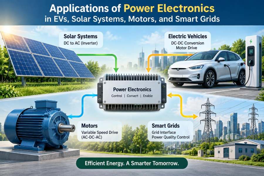

A battery-powered car pulls away smoothly from a traffic light, then slows down and returns energy to its battery. A rooftop solar array keeps producing electricity while clouds pass overhead. A factory conveyor adjusts its speed without wasting large amounts of energy. These familiar actions depend on the same engineering discipline: power electronics.
Electricity from a source is rarely in exactly the voltage, current, frequency, or waveform that a load needs. Batteries provide DC, most grids distribute AC, solar panels produce a variable DC output, and motors need carefully timed currents to deliver controlled torque.
Power electronics provides the conversion and control between source and load. It is the reason modern electrical systems can be efficient, compact, responsive, and increasingly connected.
For students, it links circuit theory, semiconductor devices, machines, control, and energy systems. For working professionals, it is central to electrification: EV drivetrains, renewable plants, industrial automation, charging networks, and smart grids.
🔌 What Power Electronics Actually Does
Power electronics is the use of semiconductor switching devices and control methods to convert, regulate, and condition electrical power. Its purpose is not mainly to process information, as in a laptop processor; it is to handle energy efficiently.
A power converter may change DC to AC, AC to DC, raise or lower voltage, alter AC frequency, or control the direction of power flow. The desired output depends on the application.
⚙️ Why Switching Makes Efficient Conversion Possible
Modern converters usually operate their transistors as electronic switches. A switch is driven either close to fully on, where voltage drop is low, or fully off, where current is low. This greatly reduces the continuous power loss that would occur in a linear regulator.
Switching is not lossless. Devices lose energy during transitions, while conducting, and through leakage. Inductors, capacitors, magnetic components, and wiring also create losses. Still, well-designed switching conversion is efficient enough to make practical EVs, variable-speed drives, and large renewable installations possible.
🧩 The Core Building Blocks of a Converter
Most power-electronic systems combine a small set of elements. Their arrangement changes, but their jobs remain recognizable.
- Power semiconductors switch or block current and voltage.
- Inductors and transformers store magnetic energy, filter current, or provide isolation.
- Capacitors smooth voltage, store short-term energy, and reduce ripple.
- Gate drivers apply the correct control signals to semiconductor gates.
- Controllers and sensors measure conditions and adjust switching commands.
- Thermal hardware removes heat from devices and connections.
🔁 The Four Fundamental Conversion Types
Converter names become easier to understand when grouped by input and output form.
| Conversion | Common converter | Typical use |
|---|---|---|
| AC to DC | Rectifier | Battery charging, DC power supplies |
| DC to DC | Chopper | Voltage regulation, EV auxiliary systems |
| DC to AC | Inverter | Motor drives, solar grid connection |
| AC to AC | AC controller or frequency converter | Motor speed and power-quality control |
Some practical systems combine several stages. An EV fast charger, for example, may rectify grid AC, correct its input current waveform, isolate and change voltage through a high-frequency stage, then precisely regulate DC delivered to the battery.
🧠 PWM: The Control Language of Power Converters
Pulse-width modulation, or PWM, controls average voltage or current by changing how long a switch remains on during each switching period. A longer on-time generally transfers more energy; a shorter one transfers less.
Filtering by inductors and capacitors, or the electrical behavior of a motor winding, converts fast pulses into a useful average waveform. PWM allows a controller to shape motor currents and synthesize AC from a DC source.
🚗 The EV Energy Path
An electric vehicle is not simply a battery connected to a motor. It is a coordinated power system with different voltage levels, operating modes, safety interlocks, cooling paths, and communications.
A typical traction path runs from the high-voltage battery through a DC link and traction inverter to the motor. During regenerative braking, that path reverses: the motor acts as a generator and the inverter directs energy back toward the battery, subject to battery and vehicle limits.
🔋 Battery Packs Need Precise Electrical Control
Battery voltage changes with state of charge, temperature, current, chemistry, and aging. A converter must therefore tolerate a range rather than assume one fixed supply voltage.
Battery management systems measure cell voltages, temperatures, and pack current. They do not replace the inverter, but they set essential operating limits. For example, a cold or nearly full pack may accept less regenerative current, even if the driver requests strong braking.
🌀 The Traction Inverter Drives the EV Motor
The traction inverter converts battery DC into controlled multi-phase AC for the propulsion motor. By controlling phase currents, it controls torque. By changing electrical frequency, it controls the motor’s rotating magnetic field and therefore its speed.
Many EVs use permanent-magnet synchronous motors or induction motors, although designs vary. The inverter and motor-control software must match the machine type; applying the same current pattern to every motor would not produce the same performance.
🎛️ Field-Oriented Control Makes Torque Predictable
Field-oriented control transforms measured phase currents into rotating reference-frame components. In simplified terms, it separates the current responsible for magnetic flux from the current responsible for torque.
This approach lets a motor controller regulate torque quickly and smoothly across a broad speed range. It is more computationally demanding than simple voltage control, but it is common where efficiency, response, and refinement matter.
♻️ Regenerative Braking Has Real Limits
Regeneration reduces waste by converting some vehicle kinetic energy into stored electrical energy. But it cannot recover all braking energy. Tire grip, motor speed, inverter current limits, battery charging capability, and passenger comfort all constrain it.
At very low speeds, regenerative torque often becomes less effective, so friction brakes still perform an essential role. Blended braking systems coordinate both sources to provide predictable pedal feel and safe stopping behavior.
🔌 Onboard Chargers and DC Fast Charging
An onboard charger takes AC from an external supply and produces regulated DC for the vehicle battery. Because it travels with the car, its size, mass, heat, cost, and power rating matter.
In DC fast charging, much of the large AC-to-DC conversion equipment is outside the vehicle. The charger supplies controlled DC directly to the battery connection, while the vehicle communicates its allowable voltage and current limits.
🧯 Isolation, Contactors, and EV Safety
High-voltage systems require more than efficient conversion. They need isolation monitoring, precharge circuits, contactors, fuses, fault detection, and carefully designed service procedures.
Precharge limits the inrush current that would otherwise occur when a battery is connected to a large DC-link capacitor. Closing a contactor directly onto an uncharged capacitor can create damaging current peaks and contact wear.
☀️ Why Solar Output Needs Conditioning
A photovoltaic module produces DC, but its voltage and current vary continuously with irradiance, temperature, shading, and operating point. The maximum available power is therefore not obtained by connecting a panel to just any load.
Power electronics allows solar energy to be collected near its best operating point and delivered in a form that batteries, local loads, or the AC grid can use.
📈 Maximum Power Point Tracking in Solar Systems
Every solar array has a current-voltage curve, and a particular operating point where voltage multiplied by current is greatest under present conditions. Maximum power point tracking (MPPT) adjusts converter operation to seek that point.
MPPT does not create extra sunlight or remove the effect of shading. It helps prevent avoidable mismatch between panel output and the electrical load. Under uneven shading, array layout and inverter architecture strongly affect how much energy can be recovered.
🔄 Grid-Tied Solar Inverters Synchronize Carefully
A grid-tied inverter converts solar DC into AC whose frequency and phase align with the local grid. It must control its output current while monitoring voltage and frequency conditions.
It also needs protective behavior. If a local grid segment becomes de-energized, an inverter generally must not continue energizing it unintentionally, because that can create hazards for utility workers and complicate restoration.
🏠 Hybrid Inverters Connect Solar, Batteries, and Loads
A hybrid inverter can coordinate a solar array, battery, grid connection, and selected loads. It may charge the battery from surplus solar, discharge it during a high-demand period, or support critical loads during an outage if the system is designed for that function.
Not every solar installation provides backup power. A standard grid-tied system may shut down during an outage even when the sun is shining. Backup capability requires appropriate inverter modes, isolation arrangements, and a defined protected-load circuit.
🌦️ Solar Design Must Account for Variability
Solar conversion design involves more than selecting a nominal kilowatt rating. Engineers examine DC voltage limits at low temperature, current limits in strong sunlight, string mismatch, cable losses, harmonic requirements, protection coordination, and thermal conditions.
A practical mistake is treating a module’s label rating as constant delivered power. Actual output depends on weather and installation conditions, while inverter limits may intentionally clip occasional high DC peaks to optimize overall system sizing.
🏭 Motor Drives Transform Industrial Energy Use
Electric motors drive pumps, fans, compressors, conveyors, elevators, machine tools, and many household appliances. When the load does not need full speed all the time, fixed-speed operation can waste energy.
A variable-frequency drive (VFD) rectifies incoming AC to a DC link and inverts it into AC of controlled voltage and frequency. This gives the motor the speed and torque required by the process rather than simply running it at line frequency.
💨 Pump and Fan Loads Reward Speed Control
For centrifugal pumps and fans, a modest speed reduction can substantially reduce power demand. This follows the affinity relationships: flow changes roughly with speed, pressure roughly with the square of speed, and power roughly with the cube of speed under comparable conditions.
That relationship is why throttling a pump with a valve or restricting airflow with a damper can be less efficient than reducing motor speed. The best choice still depends on the process, required control range, and equipment constraints.
🧲 Motor Type Changes the Drive Strategy
Induction motors are robust and widely used. Permanent-magnet motors can offer high power density and efficiency in many applications. Switched-reluctance and synchronous reluctance motors provide other trade-offs involving materials, noise, control complexity, and cost.
The converter must be chosen with the machine in mind. Voltage rating, current ripple, switching frequency, rotor position information, and fault response all influence the drive design.
⚡ Harmonics and Motor Insulation Need Attention
PWM drives create fast voltage transitions. Long motor cables can cause reflected-wave effects that raise voltage stress at motor terminals, especially with high switching speeds.
Engineers may use output filters, suitable cable practices, inverter-rated motors, and careful grounding to manage insulation stress and electromagnetic interference. A drive that controls speed well but produces unacceptable interference is not a complete design.
🌐 Smart Grids Depend on Controllable Interfaces
A smart grid is not merely a conventional grid with digital meters. It increasingly includes distributed solar, batteries, EV chargers, flexible loads, sensors, communications, and control systems.
Power electronics is the physical interface that lets many of these resources connect to the AC network. It determines how energy is exchanged and how rapidly a device can respond to voltage, frequency, and operator commands.
🔄 Bidirectional Converters Enable Flexible Energy Flow
Traditional electricity systems were designed around mostly one-way flow from large generators to customers. Batteries, EVs, and some distributed resources can require bidirectional conversion: charging in one direction and exporting in the other.
This capability supports applications such as battery storage, DC microgrids, and vehicle-to-building concepts. Whether export is permitted or useful depends on local equipment, interconnection rules, battery warranty considerations, and control coordination.
📉 Voltage and Frequency Support From Inverters
Inverter-based resources can adjust real and reactive power quickly within their electrical limits. Real power transfers usable energy, while reactive power supports electric and magnetic fields and can help manage voltage on AC networks.
These functions can improve local grid behavior, but they require correct settings. Supplying reactive power consumes some current capacity, so an inverter may have less remaining capacity for real-power transfer at a given operating condition.
🏝️ Grid-Following and Grid-Forming Are Different Roles
A grid-following inverter measures an existing grid voltage and synchronizes its current injection to it. This has been a common arrangement for solar and many battery systems.
A grid-forming inverter can establish or regulate voltage and frequency in an islanded or weak-grid setting, subject to available energy and protection design. Its control approach is more demanding because it must behave more like a voltage source while remaining stable with changing loads.
🛡️ Protection Becomes More Complex With Distributed Power
Conventional protection often assumes fault current comes primarily from large synchronous generators and follows predictable directions. Inverter-based devices may limit fault current tightly and may contribute differently depending on their controls.
This does not mean protection is impossible; it means settings, communications, fault studies, and equipment selection must reflect the actual network. Coordination becomes especially important when feeders host many generation and storage resources.
📡 Communication Helps, but It Also Adds Cyber Risk
Smart-grid control benefits from measurements and communications, but connected devices introduce cybersecurity concerns. Unauthorized control of a charger, inverter, or battery system can affect equipment operation and, at scale, grid behavior.
Practical safeguards include access control, secure update processes, network segmentation, event logging, and a safe local operating mode when communications fail. Cybersecurity is part of power-system reliability, not a separate afterthought.
🔥 Thermal Design Often Sets the Real Power Limit
Semiconductor ratings on a datasheet do not by themselves define usable converter output. Heat must travel from the chip through package materials, interface layers, heat sinks or cold plates, and finally to air or coolant.
High junction temperature accelerates aging and reduces margin. Engineers evaluate steady-state heating, short overloads, cooling-system behavior, thermal cycling, and temperature variation among parallel devices.
🧪 Silicon, Silicon Carbide, and Gallium Nitride
Silicon devices remain widely used because they are mature, capable, and available across many ratings. Silicon carbide (SiC) devices can switch efficiently at higher voltages and temperatures, making them attractive for EV traction, fast charging, and some solar applications.
Gallium nitride (GaN) devices can support very fast switching in suitable voltage ranges, often enabling compact high-frequency converters. Neither material is universally superior: cost, gate-drive needs, packaging, electromagnetic interference, reliability validation, and operating voltage all matter.
📐 Switching Frequency Is a Design Trade-Off
Higher switching frequency can reduce the required size of inductors, transformers, and capacitors. That can make a converter smaller and lighter.
However, higher frequency also tends to increase switching losses and electromagnetic noise. The best frequency is a system-level compromise among efficiency, size, cooling, acoustics, cost, and compliance requirements.
🧰 Measurements Matter as Much as the Power Stage
Control quality depends on trustworthy voltage, current, temperature, and position measurements. Sensor offset, noise, timing delay, saturation, and calibration drift can degrade efficiency or trigger incorrect protection actions.
In a motor drive, a poorly measured phase current may cause torque ripple. In a battery charger, current-sensor error can affect charge control. Engineers therefore consider sensing paths and controller timing from the start, not after hardware is finished.
🚧 Common Design Mistakes to Avoid
- Choosing a semiconductor only by voltage and current rating while neglecting switching loss and thermal impedance.
- Underestimating parasitic inductance in high-current, fast-switching layouts.
- Treating grounding, shielding, and electromagnetic compatibility as late-stage tasks.
- Ignoring startup, shutdown, fault, and abnormal-grid operating states.
- Assuming a laboratory load represents a motor, battery, grid, or solar array in the field.
- Designing controls without clear limits for current, voltage, temperature, and communication loss.
These failures are interconnected. For example, poor layout can cause voltage overshoot, which increases device stress, produces noise, and may force slower switching or larger protective margins.
🧭 A Practical Workflow for Converter Selection
Start with the energy source and load, then define voltage range, power level, direction of flow, isolation need, dynamic response, environmental conditions, applicable standards, and fault behavior.
Next, compare candidate topologies rather than immediately selecting a familiar circuit. A topology that looks efficient on paper may be unsuitable because it lacks isolation, cannot manage the required voltage range, or creates unacceptable common-mode noise.
🎓 Skills That Connect Theory to Practice
Useful power-electronics skills span several domains: circuit analysis, semiconductor behavior, magnetics, control theory, thermal design, embedded programming, PCB layout, measurement techniques, and safety practice.
Simulation is valuable for understanding waveforms and control loops, but hardware testing remains essential. Real components have parasitics, delays, temperature dependence, and tolerances that simplified models may not capture.
🌍 The Core Principle Behind Electrification
EVs, solar systems, motor drives, batteries, and smart grids appear different, yet they share a central challenge: match a changing source to a changing load safely and efficiently. Power electronics performs that matching in real time.
The strongest designs treat the converter as part of a larger system. Electrical performance, software, thermal paths, mechanical packaging, protection, grid behavior, user expectations, and maintenance all influence whether the final product works reliably.
Power electronics is the controllable energy layer that turns electricity from a raw supply into useful motion, stored energy, stable power, and flexible grids. Understanding its trade-offs is increasingly essential wherever electrical energy is generated, moved, or consumed. ⚡🔋🌐