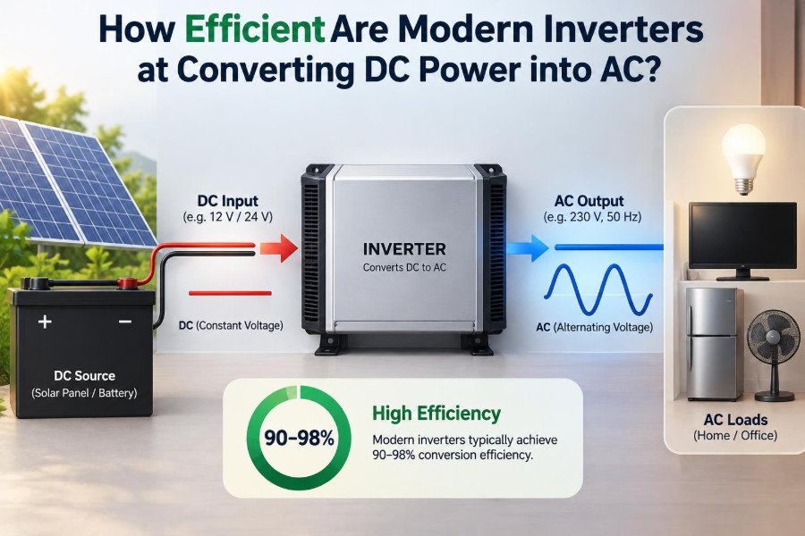

A solar battery may store energy quietly all afternoon, yet the lights, refrigerator, laptop charger, and most workshop tools expect alternating current. Somewhere between the battery terminals and the wall-style outlets, an inverter has to reshape that stored DC energy into usable AC power.
The same conversion happens in electric vehicles, backup power systems, telecom equipment, motor drives, and renewable-energy plants. It is easy to treat the inverter as a black box, until a battery seems to drain faster than expected or a unit becomes noticeably warm under load.
Efficiency answers a practical question: how much of the DC power entering an inverter actually reaches the AC load? The difference does not disappear; it becomes heat, standby consumption, electrical noise, or energy used by supporting circuits.
Modern inverters can be remarkably efficient under the right conditions, but a single percentage on a product label never tells the whole story. Their real performance changes with load, voltage, temperature, waveform quality, and the type of equipment being powered.
🔌 What an inverter actually does
DC, or direct current, flows in one direction at a relatively steady voltage. Batteries and photovoltaic panels naturally provide DC. AC, or alternating current, repeatedly reverses direction; utility grids use AC because it is practical for generation, transformation, and distribution.
An inverter uses fast electronic switches to alternate the polarity applied to its output. Control circuitry shapes those switching actions into AC at the required voltage and frequency, such as the local mains supply used by appliances.
The job is more demanding than simply flipping a switch. The output must remain stable as loads turn on, motors start, battery voltage changes, and ambient temperature rises.
📐 Defining conversion efficiency
Inverter efficiency is normally expressed as output power divided by input power:
Efficiency = (AC output power / DC input power) × 100%
If an inverter supplies 900 W to a load while drawing 1,000 W from a battery, its conversion efficiency at that operating point is 90%. The remaining 100 W is loss within the inverter system.
Efficiency is always tied to conditions. It is not a permanent property that applies equally at every output power, battery voltage, and temperature.
📊 Typical efficiency ranges in modern designs
Well-designed modern inverters often reach high efficiency near their intended operating range. Many grid-connected solar inverters have peak figures in the high nineties, while quality battery and standalone sine-wave inverters commonly achieve efficiencies in the low-to-mid nineties or better at suitable loads.
Those broad ranges are useful orientation, not a substitute for a manufacturer’s test curve. A compact low-cost inverter, a large industrial drive, and a solar inverter connected directly to a high-voltage DC string face very different design constraints.
Look for whether a stated number is a peak efficiency, a weighted efficiency, or an efficiency measured at a named load and input voltage. These values describe different things.
📈 Why peak efficiency can mislead
Peak efficiency is the best point on an inverter’s efficiency curve. It is usually measured at a moderate-to-high load where fixed internal consumption is a small portion of the total power handled.
A system that spends most of its time powering a router, a few LED lamps, and phone chargers may operate far below that point. In that situation, idle and low-load losses can matter more to battery runtime than the impressive peak number on the specification sheet.
Think of peak efficiency as a car’s best cruising condition, not its fuel use in every journey.
🧭 The efficiency curve across load levels
Most inverter efficiency curves rise sharply from very light load, level off through a useful middle-to-upper range, and may fall slightly near full rated output. The exact shape depends on topology, switching devices, cooling, and output requirements.
At light load, control electronics, display circuits, gate drivers, sensors, and magnetics still consume power. At high load, current-related losses and heating increase.
| Operating condition | Losses that often dominate | Practical implication |
|---|---|---|
| Idle or very light load | Standby electronics and fixed magnetic losses | Battery runtime can be poor despite a high peak rating |
| Moderate load | Losses are spread over useful output | Often near the most efficient region |
| Near rated load | Conduction loss, heat, and cooling demand | Efficiency may decline and derating may begin |
🌙 No-load power draw matters overnight
No-load or idle consumption is the DC power an inverter uses when it is on but supplying little or no AC load. It may support monitoring, communications, output sensing, and the circuitry needed to remain ready.
For an off-grid cabin or a vehicle left unattended, this can be a decisive specification. A modest continuous draw accumulated over many hours can remove a meaningful amount of energy from a small battery bank.
Power-saving or search modes reduce this loss by briefly checking for a load rather than maintaining the output continuously. They are useful for simple loads, but some electronic devices may not tolerate the periodic probing behavior.
⚙️ Switching devices set a major limit
Most modern inverters use power semiconductors, commonly MOSFETs at lower voltages and IGBTs or other advanced devices in higher-power applications. These devices switch current on and off thousands of times per second, or much faster in some designs.
When a switch is conducting, it has a finite voltage drop or resistance. Current flowing through it creates conduction loss, which becomes more significant as current rises.
During each transition between off and on, voltage and current briefly overlap. That produces switching loss. Designers balance switching frequency, device choice, control strategy, size, cost, electromagnetic interference, and efficiency.
🔥 Where the missing power goes
Losses are not caused by one component alone. In a real inverter, heat is generated in semiconductors, inductors, transformers where used, capacitors, circuit-board traces, connectors, and protection components.
Cooling fans also consume some energy. A fan may be a small load compared with a large appliance, but it can be noticeable in a system operating at low output for long periods.
Electrical energy can also be spent on sensing, communications, displays, and safety monitoring. These functions are valuable, especially in battery systems, but they prevent an inverter from being lossless.
🌡️ Temperature changes the result
Higher component temperature generally increases electrical resistance and can worsen semiconductor behavior. As an inverter heats up, the same load may produce slightly more loss than it did when the unit was cool.
Heat also affects reliability. Capacitors, solder joints, and power devices experience stress over long periods, so thermal design is not merely about meeting a momentary efficiency target.
Install the inverter where air can circulate, follow clearance requirements, and keep vents free of dust. A cool installation cannot eliminate conversion losses, but it helps the equipment operate nearer to its intended performance.
🔋 Input voltage influences DC-side losses
For a given output power, lower DC voltage requires higher current. A 12 V battery system delivering substantial power must carry far more current than a 48 V system delivering the same power.
Resistive loss follows the relationship P = I²R. Doubling current increases that particular loss by four times if resistance remains unchanged. This affects battery cables, fuses, terminals, and internal inverter conductors.
That is why higher-voltage battery architectures are common in larger systems. They can reduce current and cable loss, though they require suitable safety practices, protection equipment, and compatible components.
🧵 Cable losses are not inverter losses
A system can appear inefficient even when the inverter itself is performing as specified. Voltage drop in undersized or overly long DC cables wastes energy before it reaches the inverter, and can make the inverter shut down early on low-voltage protection.
Measure DC voltage at the inverter input while the load is operating, not only at the battery terminals. A significant difference indicates cable or connection loss.
Use appropriately rated conductors, short runs where practical, secure terminations, and correctly sized overcurrent protection. These are safety requirements as well as efficiency measures.
〰️ Why a pure sine-wave output helps
A pure sine-wave inverter produces an output that closely resembles utility AC. This matters because many appliances, motors, audio equipment, chargers, and control circuits are designed around sine-wave power.
A cleaner waveform can reduce unwanted heating, audible hum, and poor operation in sensitive loads. It does not mean every sine-wave inverter is equally efficient, but it is often the better technical choice for mixed household or professional loads.
The output waveform must be considered alongside efficiency rather than traded away casually for a headline number.
📶 Modified sine wave: a qualified compromise
Modified sine-wave inverters create a stepped approximation to AC. They can operate some resistive loads and simple universal-motor tools, and may be acceptable in carefully selected low-cost applications.
However, the waveform’s harmonic content can increase losses or noise in transformers, induction motors, and some electronic equipment. Certain appliances may run hot, fail to start correctly, or refuse the supply altogether.
An inverter can be internally efficient while causing a connected load to waste more energy. System efficiency includes the behavior of the load, not just the inverter’s own losses.
🌀 Motor loads are especially demanding
Refrigerators, pumps, compressors, and many power tools may require a brief starting surge several times their normal running power. The inverter must supply that surge without excessive voltage sag or protective shutdown.
Motor efficiency and power factor can also change with waveform quality and voltage regulation. Selecting an inverter only by continuous wattage can lead to disappointing real-world performance.
Check both continuous rating and surge capability, then leave margin for starting conditions. For critical motors, confirm compatibility with the manufacturer or test under controlled conditions.
🔌 Power factor affects current, not the basic watt calculation
AC loads are often described by real power in watts and apparent power in volt-amperes (VA). Power factor indicates how effectively the current contributes to real work.
A low-power-factor load can require more current for the same number of watts. That extra current places demands on the inverter output stage and may bring it closer to a VA limit even when the wattage appears acceptable.
For this reason, professional inverter specifications often state both W and VA ratings. Do not assume they are interchangeable.
☀️ Solar inverters have a different operating context
Grid-tied solar inverters usually operate over a planned DC voltage window and are often designed to spend much of the day near efficient conditions. Their efficiency may be described using weighted figures that represent performance across a range of solar output levels.
They also track the photovoltaic array’s maximum power point, a control task that extracts available energy as sunlight and panel temperature change. That tracking performance is related to system harvest, but it is distinct from DC-to-AC conversion efficiency.
Battery inverters face different conditions: wider battery-voltage variation, bidirectional operation in many cases, surge loads, and long periods at light load.
🔄 Bidirectional inverters add another path
A hybrid or battery inverter may convert DC to AC while discharging and convert AC to DC while charging. Each direction has losses, so energy that is stored and later returned undergoes more than one conversion step.
For example, energy from an AC source may be rectified to charge a battery, stored with battery losses, then inverted back into AC later. The resulting round-trip efficiency is lower than either one-way conversion efficiency alone.
That does not make storage wasteful by definition. Storage may provide backup power, time shifting, self-consumption of solar energy, or demand management. It simply means the energy accounting should include the whole path.
🏷️ Reading a specification sheet carefully
Useful specifications include continuous output rating, surge rating, DC input-voltage range, no-load consumption, efficiency at defined conditions, output waveform, allowable temperature range, and protection functions.
Be cautious with vague labels such as “up to” or “maximum” when no test condition is given. A transparent data sheet identifies the load fraction, DC voltage, temperature, and output configuration used for the claim.
- Compare like-for-like ratings: continuous output to continuous output.
- Check whether efficiency excludes external accessories and cable loss.
- Confirm the model supports the required grid, battery chemistry, and local electrical system.
- Prioritize certified equipment where safety and code compliance require it.
🧮 A practical battery-runtime estimate
Suppose a hypothetical AC load consumes 600 W and the inverter is operating at 90% efficiency. The inverter requires roughly 667 W from the battery before cable losses and battery effects are considered.
DC input power ≈ AC load power / inverter efficiency
667 W ≈ 600 W / 0.90
If the inverter’s idle draw is already included in the measured efficiency, do not add it again. If not, add it to the DC demand. Real runtime will also depend on battery capacity, discharge rate, temperature, allowable depth of discharge, and voltage cutoff settings.
This is an estimate, not a promise. Battery voltage and usable capacity vary substantially with chemistry and operating conditions.
📏 Size the inverter for the usual load, not only the largest imaginable one
An oversized inverter has useful headroom, but it may consume more at idle than a smaller unit. If it normally powers only small loads, it can spend most of its life in a poor efficiency region.
An undersized inverter has the opposite problem: it may run hot, trip during surges, or operate near its limit where stress and losses rise. The practical target is a model with enough continuous and surge capacity, without buying far more capacity than the application needs.
Listing all simultaneous loads and their starting behavior is more reliable than adding appliance nameplate watts blindly.
🧊 Cooling strategy involves trade-offs
Passive cooling avoids fan power and moving parts, but requires generous heat-sinking and may limit sustained output in a compact enclosure. Forced-air cooling supports higher power density but adds fan noise, dust exposure, and a small parasitic load.
Some units vary fan speed with temperature, reducing noise and consumption at low power. Others use sealed or liquid-cooled designs for specialized environments.
Do not block a fan simply because it is noisy. If the fan runs frequently under a modest load, investigate ambient temperature, ventilation, load level, and installation instructions.
🛡️ Protection circuits consume little but prevent major losses
Modern inverters commonly include low-voltage cutoff, overload protection, overtemperature shutdown, short-circuit protection, and fault detection. These features may interrupt power at inconvenient moments, but bypassing or defeating them creates serious equipment and fire risks.
Low-voltage cutoff is particularly misunderstood. It protects the battery and prevents the inverter from operating in a region where high input current and cable voltage drop become damaging.
Repeated protective shutdown is a diagnostic signal. It may indicate an overloaded inverter, inadequate cabling, weak battery, poor connection, unsuitable load, or insufficient ventilation.
🧪 Measuring efficiency without fooling yourself
Accurate measurement requires measuring real DC input power and real AC output power at the same time. On the DC side, use instruments suitable for the voltage and current involved; on the AC side, use a true-power meter that handles the load waveform correctly.
Testing only with a simple resistive heater gives a useful baseline, but not a complete picture. Repeat tests at several loads and, if relevant, with representative electronic and motor loads.
Keep battery voltage, temperature, and cable layout documented. Otherwise, differences in supply conditions can be mistaken for changes in inverter efficiency.
⚠️ Common interpretation mistakes
- Confusing watts with watt-hours: watts are instantaneous power; watt-hours describe energy over time.
- Using rated power as normal consumption: an inverter rating is capacity, not what it always draws.
- Ignoring idle consumption: this is costly in low-load, long-runtime systems.
- Blaming the inverter for all loss: batteries, cables, chargers, and loads have losses too.
- Assuming every appliance is waveform tolerant: compatibility matters as much as raw wattage.
🏠 Choosing for a home backup system
For a home backup installation, prioritize sine-wave quality, surge handling for refrigerators or pumps, low idle draw if outages may be long, and safe integration with the building electrical system.
Grid connection, transfer switching, earthing, neutral handling, and local code requirements are not casual DIY details. Incorrect installation can endanger workers, damage equipment, or energize conductors that should be isolated.
A qualified installer should assess systems connected to building wiring, solar arrays, or high-energy battery banks.
🚐 Choosing for vehicles and mobile work
Vehicle systems often use 12 V or 24 V batteries, making DC current and cable sizing especially critical. A modest AC load can translate into very high current on a 12 V input once conversion losses are included.
Mount the inverter close to the battery with correctly fused cables, while respecting manufacturer requirements for ventilation and separation from battery gases. Do not run high-power equipment from a vehicle system without checking alternator, battery, and duty-cycle limits.
For laptops and USB devices, direct DC-DC charging can sometimes avoid an unnecessary DC-to-AC-to-DC conversion step.
🏭 Industrial and professional applications
In industrial settings, inverter efficiency is only one design criterion. Harmonics, electromagnetic compatibility, fault behavior, redundancy, serviceability, regenerative energy, and process downtime can be equally consequential.
Variable-frequency drives are a related inverter application: they create controlled AC for motors rather than simply imitating mains power. By matching motor speed to the process demand, a drive can reduce total system energy use even though the drive itself has conversion losses.
The right question is often not “Is the inverter efficient?” but “Does the complete system use less energy while reliably doing the required work?”
♻️ Efficiency and lifetime environmental impact
Higher conversion efficiency reduces wasted energy during operation, which can matter greatly for equipment that runs many hours. It can also reduce thermal stress and cooling demand.
Yet component selection has trade-offs. Larger inductors, heat sinks, advanced semiconductors, and more complex controls can improve performance while increasing material use or cost. Long service life, repairability, appropriate sizing, and safe end-of-life handling remain part of responsible engineering.
The most efficient unit on paper is not automatically the lowest-impact choice if it is oversized, poorly installed, or replaced prematurely.
🧰 Practical ways to improve real-world performance
- Choose a sine-wave inverter with a realistic continuous and surge rating.
- Operate it near its useful load range when practical, without routinely running at maximum.
- Reduce idle time with shutdown or power-saving modes when compatible with the load.
- Use short, adequately sized DC cables and clean, tight connections.
- Keep the inverter cool, dry, and free from blocked ventilation.
- Eliminate avoidable conversion stages by using DC-powered equipment where it makes sense.
- Monitor input voltage, output load, and fault history rather than relying on assumptions.
🔍 When a lower stated efficiency may still be sensible
A product with a slightly lower quoted peak efficiency can still be the better choice if it has much lower standby draw, stronger surge performance, better monitoring, appropriate approvals, quieter operation, or support for the required battery system.
Likewise, a highly efficient grid-tied solar inverter may be unsuitable for an off-grid battery backup role. Application fit determines value.
Compare the expected energy profile over a day or year, not merely the largest percentage printed in a brochure.
🧠 The core principle: evaluate the whole energy path
Modern inverters are efficient enough that their losses are often modest at favorable loads, but they are never invisible. Fixed consumption dominates at light load; current and heat dominate as power rises; waveform and load behavior affect the useful energy that reaches the final task.
Evaluate DC source, cables, inverter, output waveform, appliance type, operating schedule, and installation environment as one system. That approach reveals whether an apparent efficiency problem is genuinely inside the inverter or elsewhere in the energy path.
The best inverter is not simply the one with the highest peak percentage; it is the one that delivers compatible, safe AC power with the lowest practical losses in its actual operating conditions.
Choose from measured conditions rather than headline claims, and an inverter becomes a dependable bridge between stored DC energy and useful AC work. ⚡🔋📈