
A phone charger that feels warm, a dim lamp at the end of a long cable run, and a motor enclosure that runs hotter than expected all point to the same underlying issue: some electrical input is not reaching the intended load.
That missing energy has not disappeared. In most practical circuits, it has become heat in wires, contacts, windings, electronic components, or magnetic materials. A small loss may be harmless; a persistent or unexpected loss can waste energy, reduce performance, shorten equipment life, and create a safety concern.
For students, power-loss calculations turn Ohm’s law into a practical design tool. For working professionals, they support conductor sizing, thermal checks, energy-cost decisions, troubleshooting, and maintenance planning.
The useful question is not simply “How much power does the circuit use?” It is “Where is the power going, why is it being lost there, and what change reduces that loss without creating a new problem?”
🔌 What Power Loss Means in a Circuit
Power loss is electrical power that is supplied to a circuit but is not delivered as useful output by the intended load. In a heater, heat is the desired output. In a cable feeding a motor, heat generated in the cable is usually an unwanted loss.
Power is measured in watts. It describes the rate at which energy is transferred or converted: one watt equals one joule per second. Losses may occur in conductors, connectors, switches, transformers, capacitors, semiconductors, and loads with non-ideal behavior.
A circuit can still operate while losing power. The design issue is whether the loss is acceptable for its efficiency, temperature rise, voltage regulation, operating cost, and reliability requirements.
⚖️ Useful Power Versus Dissipated Power
Separating useful output from dissipation prevents a common misunderstanding. A load’s rated power is not automatically circuit loss. A fan motor, for example, draws electrical power, converts part of it into shaft output, and dissipates the remainder as heat, sound, and internal losses.
In a simple DC feeder, the source power can be written as the sum of load power and wiring loss:
P_source = P_load + P_wiring loss
Real systems can include more terms, such as converter loss and contact loss. This energy balance is a powerful troubleshooting check: if measured input is greater than the known useful output, the difference must be accounted for somewhere.
📐 The Core Equations for Electrical Power
For a DC circuit, or an AC circuit using RMS values with a resistive load, electrical power is:
P = VI
where P is power in watts, V is voltage in volts, and I is current in amperes. Combining this relationship with Ohm’s law gives two particularly useful forms:
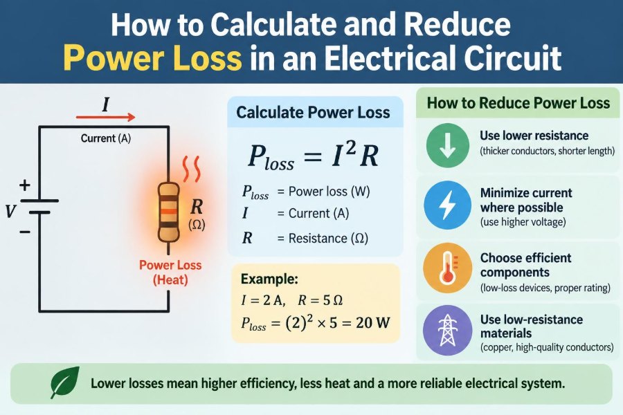
P = I²R
P = V²/R
Choose the form that uses quantities you know. The expression I²R is especially important for conductor and contact losses because it shows why current has such a strong effect on heating.
🔥 Why Resistance Produces Heat
Electrical resistance impedes the organized movement of charge. As charge carriers move through a resistive material, energy is transferred to the material’s atoms. At ordinary circuit scales, the result is commonly observed as heat.
This is called Joule heating or resistive heating. It is deliberately used in toasters, electric heaters, and fuse elements. In supply wiring, it is normally an unavoidable side effect that designers seek to keep within thermal and efficiency limits.
The relationship is not mysterious: a wire with resistance carrying current dissipates I²R watts. Even a low resistance can produce meaningful heat when current is high.
🧮 Calculating Wire Loss Step by Step
Consider a hypothetical 24 V DC device drawing 10 A through a supply-and-return cable pair. Suppose the total resistance of both conductors together is 0.08 Ω. The cable loss is:
P_loss = I²R = 10² × 0.08 = 8 W
The voltage drop across the pair is:
V_drop = IR = 10 × 0.08 = 0.8 V
The device receives about 23.2 V rather than 24 V. The source supplies 240 W, the cable dissipates 8 W, and approximately 232 W is available at the load, assuming no other losses. This simple example also shows why voltage drop and power loss should be evaluated together.
🛣️ Include the Complete Current Path
A frequent calculation error is using only the one-way cable length. Current must leave the source and return to it, so the resistance of the full loop matters in a two-wire DC circuit.
For example, 20 m from source to load generally means about 40 m of conductor in the current path when separate outgoing and return conductors are used. In AC systems, the return path may be a neutral, another phase conductor, or an engineered grounding arrangement depending on the system.
Do not assume the protective earth conductor is the intended return path. Under normal operation, it should not carry load current in standard protective arrangements.
🧵 Finding Conductor Resistance
Conductor resistance depends primarily on material, length, cross-sectional area, and temperature. For uniform conductors, the ideal relationship is:
R = ρL/A
Here, ρ is resistivity, L is length, and A is cross-sectional area. Copper and aluminum have different resistivities; a larger area reduces resistance, while a longer conductor increases it.
In field work, manufacturer data is often more practical than calculating from material properties. Use the published resistance for the specific conductor size, material, stranding, and temperature basis, then multiply by the relevant path length.
🌡️ Temperature Changes the Result
For common metallic conductors, resistance rises as temperature rises. A cable measured when cool will therefore have lower resistance than the same cable at elevated operating temperature.
This matters because heating can reinforce itself: current causes loss, loss raises conductor temperature, and higher temperature raises resistance. Protective devices, insulation ratings, installation method, and ambient conditions are intended to keep this behavior within safe limits.
For approximate early-stage calculations, a reference resistance may be sufficient. For high-current designs, long feeders, enclosed installations, or tight voltage limits, use temperature-corrected data and applicable engineering rules.
📉 Voltage Drop and Power Loss Are Related but Different
Voltage drop is the reduction in voltage between the source and the load. Power loss is the power dissipated in the impedance causing that drop. For a resistive conductor, they are linked by:
P_loss = V_drop × I
A circuit may have a voltage drop that is acceptable for one load but not another. Incandescent lamps visibly dim with reduced voltage, some electronics shut down below a threshold, and motors can draw problematic current or lose torque when supply voltage falls.
Always assess both quantities. A small voltage drop at a very large current can still represent substantial heat, while a modest wattage loss can be critical in a low-voltage control circuit.
📈 Why Current Is the Biggest Lever
Because resistive loss is proportional to the square of current, doubling current makes conductor loss four times larger if resistance stays unchanged. This is why low-voltage, high-current distribution requires particularly careful conductor sizing.
Consider the earlier 0.08 Ω cable pair. At 5 A, its loss is 2 W. At 10 A, it is 8 W. At 20 A, it becomes 32 W. The resistance did not change much, but the thermal consequence did.
Reducing current is often more effective than making a small reduction in resistance. That principle explains the use of higher voltages for transmitting a given amount of power over distance.
⚡ Higher Voltage Can Reduce Distribution Loss
For a required power level, current is approximately P/V in a DC or unity-power-factor system. If voltage increases while delivered power remains the same, current decreases. Lower current reduces I²R loss in the conductors.
This is a distribution principle, not a blanket instruction to raise voltage. Higher voltage introduces different insulation, clearance, switching, protection, shock, and arc-flash considerations. It may also require conversion equipment at each end.
The right choice balances conductor loss against the practical and safety demands of the voltage class. A design that minimizes watts in a cable may be unsuitable if it complicates the complete system.
🔩 Contact Resistance: The Small Problem That Grows
Terminals, plugs, switches, relays, fuses, and crimp joints all have some contact resistance. A clean, tight, correctly rated connection has very low resistance, but corrosion, contamination, vibration, damage, poor crimping, or loose torque can increase it.
At high current, a small increase matters. A contact resistance of 0.01 Ω carrying 30 A dissipates 9 W. Concentrated in a small metal interface, that power can create a much higher local temperature than the same loss spread along a long cable.
Hot, discolored, softened, or oxidized connections deserve prompt investigation. Do not simply tighten an energized connection; follow isolation, lockout, and equipment-specific safety procedures.
🧲 Losses in Motors and Transformers
Not all losses are simple wire resistance. Motors and transformers also contain winding loss, but their magnetic cores can dissipate energy through hysteresis and eddy currents. Mechanical losses from bearings, friction, and air movement also affect motors.
These losses vary with operating conditions. A motor can be inefficient when lightly loaded, overloaded, poorly cooled, misaligned, or operated with unsuitable supply quality. A transformer may have core loss whenever energized and winding loss that increases with load current.
Nameplate efficiency is useful context, but it represents specified operating conditions rather than every real installation. Measure and inspect when actual performance matters.
🌊 AC Circuits Need RMS Values
In sinusoidal AC analysis, use RMS voltage and RMS current for heating and real-power calculations. RMS values represent the DC-equivalent heating effect in a resistor.
For a purely resistive single-phase load, real power is:
P = V_RMS × I_RMS
For many AC loads, current and voltage are not perfectly aligned in time. Then the real power is:
P = V_RMS × I_RMS × power factor
A basic meter may show voltage and current without revealing their phase relationship or waveform distortion. For meaningful AC energy measurements, use instruments appropriate to the waveform and load type.
🧭 Real, Reactive, and Apparent Power
AC systems use three related quantities. Real power, measured in watts, performs useful work or becomes heat. Reactive power, measured in vars, moves energy back and forth between sources and reactive elements such as inductors and capacitors. Apparent power, measured in VA, is the product of RMS voltage and current.
Power factor is real power divided by apparent power in the simple sinusoidal case. Lower power factor can require more current for a given real-power output, which increases conductor losses and may affect equipment capacity.
Power-factor correction can help some installations, but it must be engineered for the load, switching conditions, harmonics, and utility or facility requirements. A capacitor bank is not a universal remedy.
〰️ Harmonics Can Add Hidden Heating
Nonlinear loads such as many electronic power supplies, variable-speed drives, and LED drivers can draw non-sinusoidal current. Harmonic currents can increase RMS current and create extra heating in conductors, transformers, and some neutral conductors.
Standard formulas still apply to resistive loss when the true RMS current and relevant resistance are known. The difficulty is obtaining valid measurements and accounting for frequency-dependent effects in larger or specialized systems.
A true-RMS meter may be suitable for basic checks within its specifications. Complex facilities may require a power-quality analyzer and a review by a qualified electrical professional.
📏 Selecting a Larger Conductor
Increasing conductor cross-sectional area lowers resistance and therefore reduces voltage drop and I²R loss. This is often the most direct solution for long runs or high-current feeders.
However, “bigger” is not automatically the best answer. Larger conductors cost more, can be harder to terminate correctly, may exceed equipment lug ranges, and can complicate routing. The final selection must satisfy ampacity, insulation, installation environment, voltage-drop goals, fault performance, and governing requirements.
A useful design process compares lifecycle consequences: the initial material cost against expected energy dissipation, temperature margin, performance, and maintainability.
🧰 Improve Connections Before Replacing Cables
When loss is localized at a joint, replacing an entire cable may not solve the root cause. Inspect termination quality, conductor preparation, compatible materials, torque requirements, mechanical strain, corrosion exposure, and evidence of overheating.
Good connection practice typically includes:
- Using terminals and tools approved for the conductor type and size.
- Following specified stripping lengths and crimp procedures.
- Applying manufacturer torque instructions where torque is specified.
- Keeping moisture and contaminants away from connections.
- Providing strain relief so vibration and pulling do not loosen the joint.
Never apply conductive grease, cleaning products, or improvised repairs without confirming their suitability for the equipment and connection materials.
🧊 Keep Components Within Their Thermal Limits
Power loss becomes a temperature problem only after heat cannot leave as fast as it is generated. Enclosures, bundling, insulation, ambient temperature, airflow, mounting surfaces, and nearby heat sources all influence this balance.
Two circuits with identical current and resistance can run at very different temperatures if one cable is in free air and the other is tightly grouped in a hot enclosure. Component datasheets and installation rules often include derating information for this reason.
Cooling can reduce temperature, but it does not eliminate the underlying electrical loss. Treat ventilation as part of a thermal design, not as permission to ignore undersized wiring or failing contacts.
🔍 Measure Loss Without Guessing
Calculation should guide measurement, and measurement should test assumptions. Begin by measuring source voltage, load-end voltage, and current under representative operating conditions. The difference between source and load voltage reveals total path drop.
To locate a problem, measure voltage across individual connections, fuses, switches, and cable segments while current is flowing. An unexpectedly large drop across one small component indicates resistance at that location.
Useful tools may include a properly rated digital multimeter, clamp meter, milliohm meter, thermal camera, and power analyzer. Their use around energized equipment carries shock and arc hazards; select equipment ratings and procedures appropriate to the installation.
🌡️ Thermal Imaging as a Diagnostic Clue
Thermal imaging can quickly reveal unusually warm terminals, breakers, fuses, and conductors under load. It is especially valuable for comparing similar phases or similar connections in the same operating environment.
It does not directly measure resistance or power loss. Surface temperature depends on emissivity, reflections, airflow, load history, and the component’s ability to shed heat. A shiny metal surface can be particularly misleading to an infrared camera.
Use a hot spot as a reason to investigate, then confirm with electrical measurements and a physical inspection performed safely. Temperature patterns are evidence, not a complete diagnosis by themselves.
🧪 A Practical Calculation Workflow
Use a repeatable sequence rather than jumping straight to a single formula:
- Define the load, nominal voltage, expected current, route length, and operating duty.
- Map the complete current path, including return conductors, connectors, protective devices, and switches.
- Obtain resistance data for conductors and significant components at a suitable temperature basis.
- Calculate voltage drop with
V_drop = IRand loss withP_loss = I²R. - Check load-end voltage, component heating, conductor ampacity, and protection coordination.
- Validate the result with measurements under representative load.
For AC equipment, add power factor, waveform, and phase-balance considerations as needed.
🚧 Common Calculation Mistakes
Many incorrect loss estimates come from simple omissions rather than difficult mathematics. Watch for these errors:
- Using one-way length when the complete loop resistance is needed.
- Confusing conductor ampacity with an acceptable voltage-drop target.
- Using nominal current instead of the actual or worst credible operating current.
- Ignoring temperature rise and connection resistance.
- Using average-responding meter readings for distorted waveforms.
- Assuming all input power reaches the intended load.
Another mistake is treating a calculated value as permanent. Loads, ambient conditions, connection quality, and equipment age can change the result over time.
🏭 Three-Phase Systems Require Careful Bookkeeping
Balanced three-phase systems can transmit substantial power efficiently because power is shared among phases. For a balanced system, real power is commonly calculated as:
P = √3 × V_line-to-line × I_line × power factor
Conductor loss still depends on the resistance and RMS current in each conductor. Do not divide a total current or loss by three unless the circuit arrangement and measurement basis justify it.
Imbalance can increase losses, create neutral current in applicable systems, and cause uneven motor heating. Measure each phase, verify loading, and investigate persistent phase-to-phase differences.
🔋 Battery and Low-Voltage DC Systems
Battery systems make voltage drop especially visible. A few volts lost in a high-voltage feeder may be tolerable, while a fraction of a volt lost in a 12 V circuit can materially affect charging, lighting, electronics, or motor starting.
Battery internal resistance also causes loss. Under high current, terminal voltage falls because part of the battery’s energy is dissipated internally. Cable loss, fuse loss, and connector loss add to that effect.
Use short runs where possible, adequately sized conductors, secure corrosion-resistant connections, and properly rated overcurrent protection placed according to the system’s safety design. Batteries can deliver dangerous fault current even at low nominal voltage.
🖥️ Power Electronics Have Their Own Loss Mechanisms
Converters, rectifiers, inverters, regulators, and switching supplies dissipate power through semiconductor conduction loss, switching loss, magnetic losses, capacitor losses, and control circuitry. Their efficiency changes with input voltage, output load, switching frequency, temperature, and operating mode.
A device with high peak efficiency may still waste meaningful energy at very light load. Conversely, choosing a much larger converter than needed can add idle consumption and cost without solving a real constraint.
Use manufacturer curves when available, allow for cooling, and confirm that the converter’s input and output ratings cover transients as well as steady-state operation.
🛡️ Protection Devices Also Have Voltage Drop
Fuses, circuit breakers, contactors, disconnects, and current sensors are not ideal zero-resistance parts. Their voltage drop is often small when correctly selected and healthy, but it becomes relevant in low-voltage or high-current circuits.
Do not bypass a protective device to recover a little voltage or reduce loss. Protection limits fault energy and helps prevent conductor and equipment damage. Instead, choose a properly rated device with suitable characteristics and investigate abnormal heating or drop.
Any changes to protection should consider fault current, interruption rating, conductor protection, coordination, and applicable installation requirements—not just normal-load watts.
📊 Efficiency Is a System-Level Measurement
Efficiency is the ratio of useful output power to input power:
Efficiency = P_useful output / P_input × 100%
Its boundary must be stated. A motor efficiency may exclude feeder loss. A pump system efficiency includes additional mechanical and hydraulic effects. A battery-powered system may include charging, storage, conversion, and load losses depending on the question being asked.
Defining the boundary prevents misleading comparisons. A highly efficient device does not guarantee an efficient installation if it is fed by long undersized conductors or operated far from its intended duty point.
🧾 Turn Watts Lost Into Energy and Cost
Power is an instantaneous rate; energy accumulates over time. If a loss is approximately constant, energy loss is:
Energy = Power loss × operating time
For example, an 8 W cable loss operating for 10 hours dissipates 80 Wh, or 0.08 kWh. To estimate cost, multiply energy by the applicable electricity rate, recognizing that commercial tariffs and demand charges can be more complex than a single rate.
This conversion helps prioritize upgrades. A loss that seems minor for an occasional load may matter when it occurs continuously across many circuits.
🧩 Choose the Right Reduction Strategy
The best corrective action depends on where and why loss occurs. Start with the dominant source rather than making a generic upgrade.
- For long-cable loss: shorten the path, increase conductor area, or distribute at a higher voltage where appropriate.
- For hot joints: repair or replace the termination and correct the installation cause.
- For motor loss: check loading, voltage balance, alignment, bearings, cooling, and control settings.
- For poor AC power factor or harmonics: measure first, then design a targeted solution.
- For converter loss: select suitable topology, rating, operating point, and cooling.
Reducing one loss can shift heat or cost elsewhere, so assess the complete system after every significant change.
✅ The Core Principle: Control Current, Resistance, and Heat
Most circuit-loss work comes back to a disciplined chain of reasoning. Identify current, map every meaningful resistance in the path, calculate the resulting voltage drop and I²R heating, then check whether the physical installation can safely dissipate that heat.
For AC and electronic systems, extend the same habit to RMS current, power factor, harmonics, switching behavior, and magnetic losses. The equations remain valuable, but correct inputs and a clear system boundary matter just as much.
Good designs do not merely deliver power at startup. They maintain acceptable voltage, temperature, protection, and efficiency through real operating conditions and over the equipment’s service life.
Calculate losses from the actual current path, verify them under load, and reduce them by addressing the resistance or current that creates the heat. That approach turns a basic formula into safer, more reliable electrical engineering. ⚡🔧📈